MX2020 Component Redundancy
A fully-configured router is designed so that no single point of failure can cause the entire system to fail. Only a fully-configured router provides complete redundancy. All other configurations provide partial redundancy. The following major hardware components are redundant:
Host subsystem—The host subsystem consists of a Routing Engine functioning together with a Control Board. The MX router can have one or two host subsystems. Each host subsystem functions as a unit—the Control Board and Routing Engine (CB-RE). To operate, each host subsystem requires one or two Routing Engines installed into the front of the chassis in vertical slots labeled 0 and 1. If two CB-REs are installed, one functions as the primary and the other functions as the backup. If the primary host subsystem (or either of its components) fails, the backup can take over as the primary. See MX2000 Host Subsystem CB-RE Description.
If the Routing Engines are configured for nonstop active routing, the backup Routing Engine automatically synchronizes its configuration and state with the primary Routing Engine. Any update to the primary Routing Engine state is replicated on the backup Routing Engine. If the backup Routing Engine assumes primary role, packet forwarding continues through the packet transport router without interruption.
Power system—The MX2020 router has up to four power distribution modules (PDMs) that share the load evenly. If one PDM fails in a fully redundant power system that includes two PDMs and nine power supply modules (PSMs), the other PDM can provide full power to the MX router indefinitely. PSM redundancy varies depending on the number of PSMs and number of Field Replaceable Units (FRUs). See the MX2020 Power Subsystem Description for more information about power system redundancy.
PSMs—All PSMs in the power subsystem share the load (the nine PSMs in the upper card cage share the load, and the nine PSMs in the lower card cage share the load). If one PSM fails in a redundant configuration, the remaining PSMs provide power to FRUs. In the AC, DC, 240 V China, or universal high voltage AC (HVAC), or high voltage DC (HVDC) configuration, up to eighteen PSMs may be required to supply power to a fully configured router.
In a fully configured MX2020 router with 18 PSMs, the nine PSMs in the upper card cage and the nine PSMs in the lower card cage supply power to:
10 line-card slots
Four Power Distribution Modules (PDMs)
20 Modular Port Concentrators (MPCs) (10 MPCs per zone)
Two fan trays
Eight Switch Fabric Boards (SFBs)
Two Control Board and Routing Engines (CB-REs)
A portion of power from each zone is reserved to power critical FRUs. These FRUs allow the system to operate even if power to a complete zone fails.
DC power subsystem—The MX2020 DC power system (-48 V and 240 V China) is comprised of two subsystems. Each DC power subsystem provides power to 10 line-card slots, three fan trays, two CB-REs, and eight SFBs. There are nine DC PSMs and two DC PDMs in each power subsystem. This means, if one power subsystem stops functioning for any reason, only the MPCs will stop functioning; the router will continue to function.
Figure 1 illustrates feed redundancy for the MX2020 DC power subsystem.
Figure 1: MX2020 Router DC Power Subsystem Feed Redundancy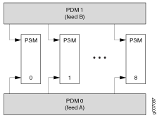
Each DC power subsystem has two power zones: zone 0 and zone 1. A portion of power from each zone is reserved to power critical FRUs. These FRUs allow the system to operate even if power to a complete zone fails. Some FRUs draw power only from zone 0, some FRUs draw power only from zone 1, and some FRUs draw power from both zone 0 and zone 1.
There are two types of DC power subsystems available for the MX2020: a “base” DC power subsystem (MX2020-BASE-DC) and an “optimized” or premium DC power subsystem (MX2020-PREMIUM2-DC). The fan trays in an optimized DC power subsystem draw power from the power zones differently than the fan trays in a base DC power subsystem. In a base DC power subsystem, two of the four fan trays draw power from both zones. In the optimized DC power subsystem, two of the fan trays draw power from only one zone. Because of this, the optimized power subsystem requires less power. See Determining DC Power Requirements for Your MX2020 Router for more information about MX 2020 power distribution.
Figure 2 illustrates how the power zones in the MX2020 base DC power subsystem distribute power to FRUs
Figure 2: Power Distribution in a DC Base Power Subsystem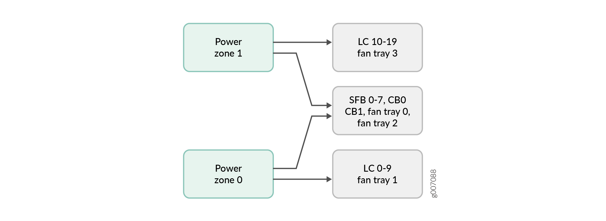
Figure 3 illustrates how the power zones in the MX2020 optimized DC power subsystem distribute power to FRUs
Figure 3: Power Distribution in an Optimized DC Power Subsystem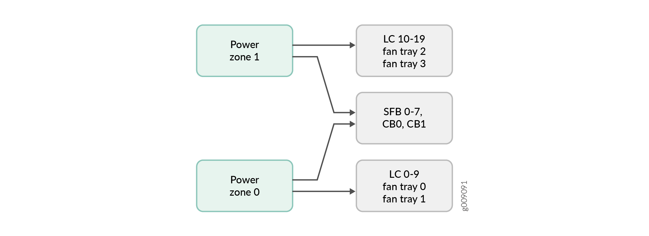
DC PSMs—The MX2020 DC PSMs (-48 V) and DC PSMs (240 V China) are hot-removable and hot-insertable. The DC PSMs are a dual redundant feed (INP0 and INP1). To provide feed redundancy, you can connect each DC PSM to two separate feeds from different sources. When both input feeds are present, power is drawn from the feed supplying higher DC voltage. You can set these feeds by using the input mode DIP switch located on the DC PSM (see MX2020 DC Power Supply Module (-48 V) Description).
DC PDMs (-48 VDC or 240 V China) There are two PDMs per power subsystem capable of carrying seven feeds or nine feeds each. You can install a total of four PDMs into a router. Each DC PDM 240 V China) or DC PDM (-48 V) operates with seven feeds or nine feeds of either a 60-A or 80-A current limit. The capacity of these feeds is relayed to system software through a switch located on the DC PDM. In a redundant configuration, the seven-feed DC PDMs support a total of fourteen 60-A or 80-A feeds, and the nine-feed DC PDMs support a total of eighteen 60-A or 80-A feeds. Each DC PSM is capable of delivering 2500 W of power if 80-A feeds are connected. In the DC configuration, each subsystem provides N+1 PSM redundancy along with N+N feed redundancy. The power feeds from different sources need to be connected to different PDMs. If feeds that connect to one PDM fail in a redundant configuration, the other feed will provide full power.
Note:The selected input capacity applies to all inputs of this PDM. Selecting 60-A reduces the available power output capacity of the PSMs supplied by this PDM.
Note:Depending on the voltage of the DC feeds (-48 VDC or 240 V China), power can be drawn from both feeds. The feed with higher voltage provides more power. If the difference between the voltages is sufficient, then the higher voltage feed provides all the power. When the voltages are exactly the same, equal power is drawn from both feeds.
DC PDMs (240 V China)—There are two PDMs per power subsystem capable of carrying nine feeds each. You can install a total of four PDMs (240 V China) into a router. Each DC PSM is capable of delivering 2500 W of power. In the DC configuration, each subsystem provides N+1 PSM redundancy along with N+N feed redundancy. The power feeds from different sources need to be connected to different PDMs. If feeds that connect to one PDM fail in a redundant configuration, the other feed will provide full power.
Note:Depending on the voltage of the DC feeds, power can be drawn from both feeds. The feed with higher voltage provides more power. If the difference between the voltages is sufficient, then the higher voltage feed provides all the power. When the voltages are exactly the same, equal power is drawn from both feeds.
High-Voltage Second-Generation Universal (HVAC/HVDC) PDMs—There are two PDMs per power subsystem capable of carrying nine feeds each. The universal PDM accepts either an HVAC or HVDC input. You can install a total of four PDMs into a router. Each universal PDM operates with nine feeds of a 30-A current limit. Each universal PSM is capable of delivering 3400 W of power with-dual feeds and 3000 W of power with a single-feed. In this configuration, each subsystem provides N+1 output PSM redundancy along with N+N feed redundancy. The power feeds from different sources need to be connected to different PDMs. If feeds that connect to one PDM fail in a redundant configuration, the other feed will provide full power. Both input power feeds are active, and share the load when they are present.
Figure 4 and illustrate the power distribution from the universal (HVAC/HVDC) PDMs to the universal (HVAC/HVDC) PSMs.
Figure 4: MX2020 Router Universal (HVAC/HVDC) Power Subsystem Feed RedundancyAC power subsystem—The AC power subsystem is feed redundant. Each PSM takes in two AC feeds and uses one of the two. One AC feed is active at a time. If one feed fails, the PSM automatically switches over to the other feed without disrupting system function. In the three-phase power systems, the AC power going to the PSMs is split into three individual phases (wye) or a pair of phases (delta). Each PSM works on a single phase; therefore, the power system works independent of the type of AC feed connected. You can connect one or two AC feeds, depending on the power system configuration (number of PSMs, redundancy, and so on). Each phase from each of the two feeds is distributed among one or two PSMs. One feed has each phase going to two PSMs, and the other feed has each phase going to a single PSM.
AC PSM—The MX2020 AC PSMs are hot-removable and hot-insertable. The AC PSMs have a dual redundant feed (INP0 and INP1). One input feed is active during operation. These feeds are set by the input mode DIP switch located on the AC PSM (see MX2020 AC Power Supply Module Description). Each AC PSM works with a single phase derived from either three-phase delta 200-240 VAC (line-to-line) or three-phase wye 200-240 VAC (line-to-neutral). Each AC PSM is capable of delivering 2500 W of power.
AC PDM—Up to nine PSMs can be connected through the AC PDM. The MX2020 supports connection of a single-phase or three-phase (delta or wye) AC PDM. The three-phase AC PDMs require two three-phase feeds to be connected. Each phase from each of the two feeds is distributed among one or two PSMs. One feed has each phase going to two PSMs, and the other feed has each phase going to a single PSM. The single-phase AC PDM provides an AC input connection from the single-phase AC power source, and also provides an input power interface to the PSM through a system power midplane. Each AC input is independent and feeds one PSM.
Figure 5 and Figure 6 illustrate the power distribution from the three-phase delta and wye PDMs to the AC PSMs.
Figure 5: Power Distribution from Three-Phase Feed Delta PDM to the AC PSMs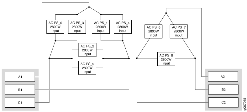 Figure 6: Power Distribution from Three-Phase Feed Wye PDM to the AC PSMs
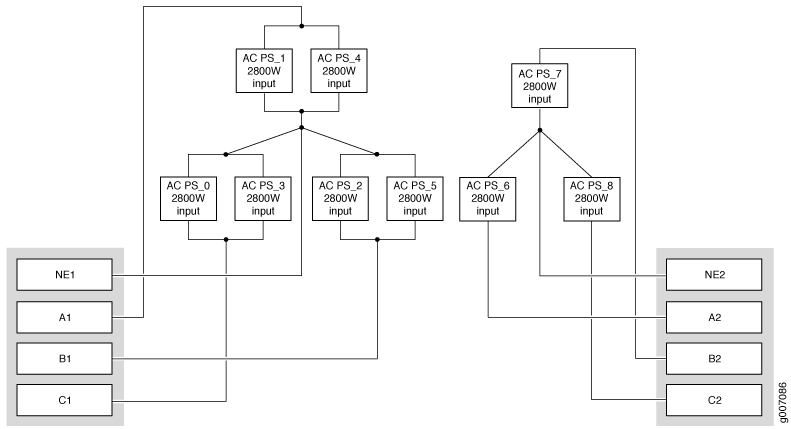
AC power requirements—Table 1 shows the MX2020 current requirements for the three-phase delta, three-phase wye, and single-phase power feeds.
Table 1: AC PDM Current Requirements Three–Phase Voltage
Input Feed
Current Delta per Three-Phase PDM
Current Wye per Three-Phase PDM
Current per Single Phase PDM
200 V (minimum–nominal) (line-to-line) for delta (per phase)
1
50 A
–
2
25 A
–
200 V (minimum–nominal) (line-to-neutral) for wye (per phase)
1
–
30 A
2
–
15 A
200 V (minimum–nominal)
1
–
–
14 A
Note:This is the minimum required to provide 2.5KW per PSM. Based on facilities guidelines, you should over-provision the MX2020 router. The two numbers listed in the three-phase delta and three-phase wye current columns reflect the distribution of phases from the feed to the PSM. For example, from one feed, each phase goes to two PSMs, and from the other feed, each phase goes to only one PSM.
Cooling system—The cooling system in a fully-configured MX2020 router has a total of four fan trays, which are controlled by the host subsystem. If one of the fans fails, the host subsystem increases the speed of the remaining fans to provide sufficient cooling for the router. See MX2020 Cooling System Description).The fan trays are powered by two power subsystems that are divided into zones. The fan trays draw power from each zone depending upon whether you have a base DC power subsystem (MX2020-BASE-DC) or an optimized DC power subsystem (MX2020-PREMIUM2-DC). In the base DC power subsystem, two of the four fan trays draw power from both zones. In the optimized DC power subsystem, two of the fan trays draw power from only one zone. See Determining DC Power Requirements for Your MX2020 Router for more information about MX 2020 power distribution.