Help us improve your experience.

Let us know what you think.

Do you have time for a two-minute survey?


Replacing an MX2000 High-Voltage Second-Generation Universal (HVAC/HVDC) Power Supply Module

Removing an MX2000 Router High-Voltage Second-Generation Universal (HVAC/HVDC) Power Supply Module

Before you remove a PSM, be aware of the following:

CAUTION:

To maintain proper cooling and prevent thermal shutdown of the operating PSM, each PSM slot must contain either a PSM or a blank panel. If you remove a PSM, you must install a replacement PSM or a blank panel shortly after the removal.

Note:

After powering off a PSM, wait at least 60 seconds before turning it back on.

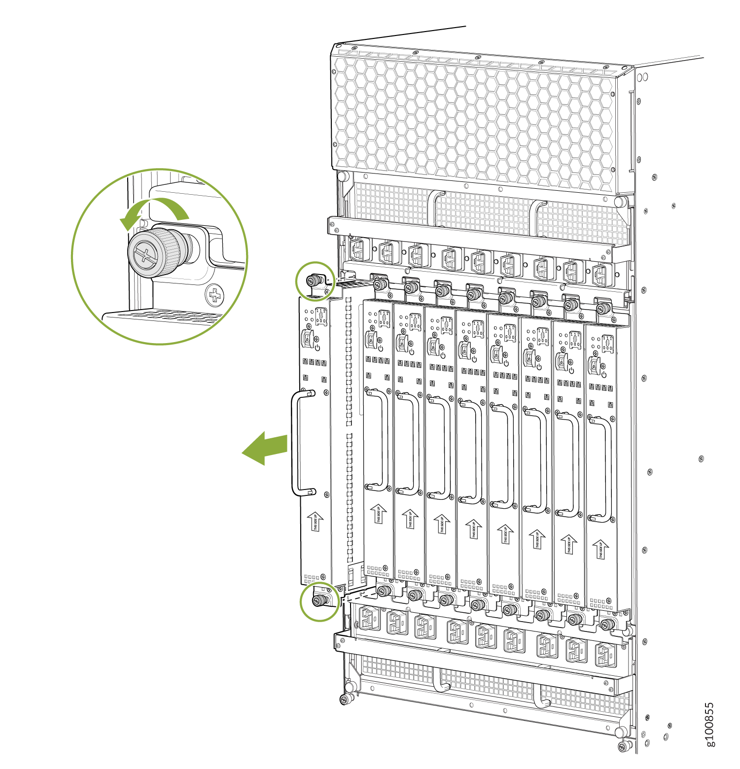
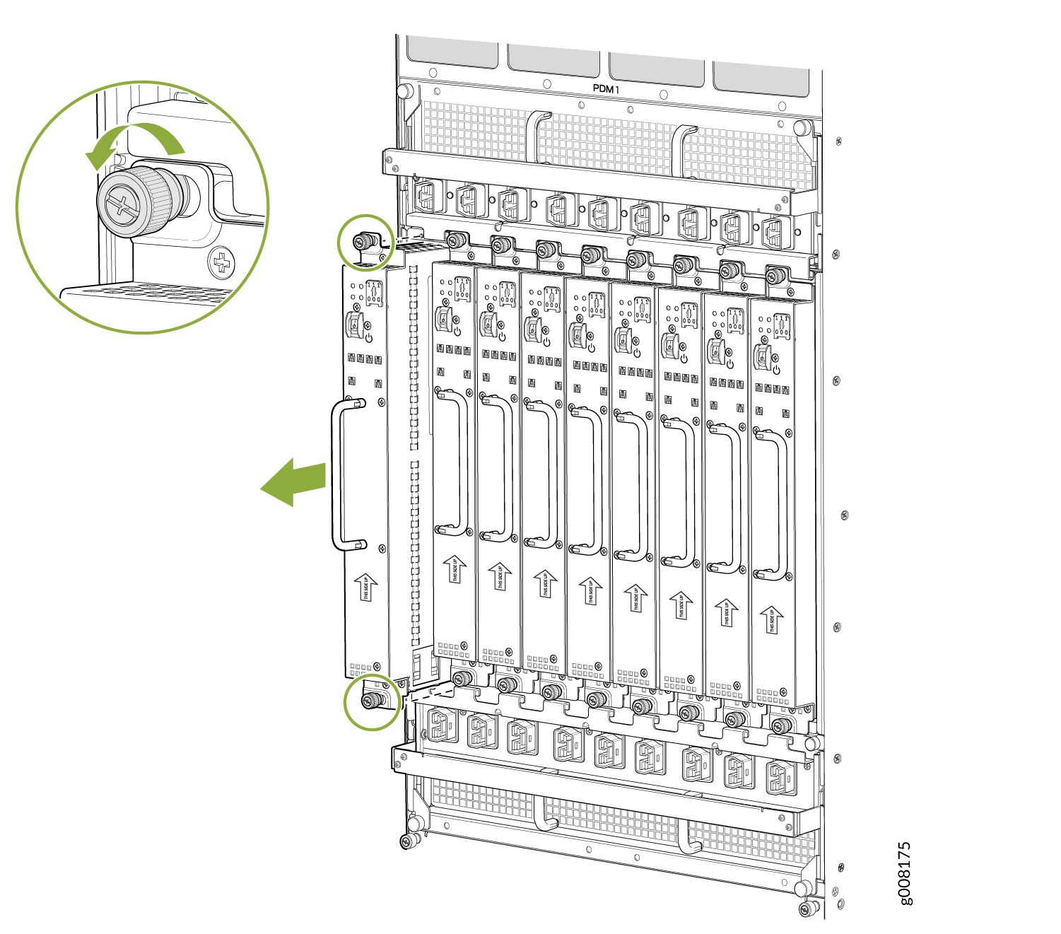
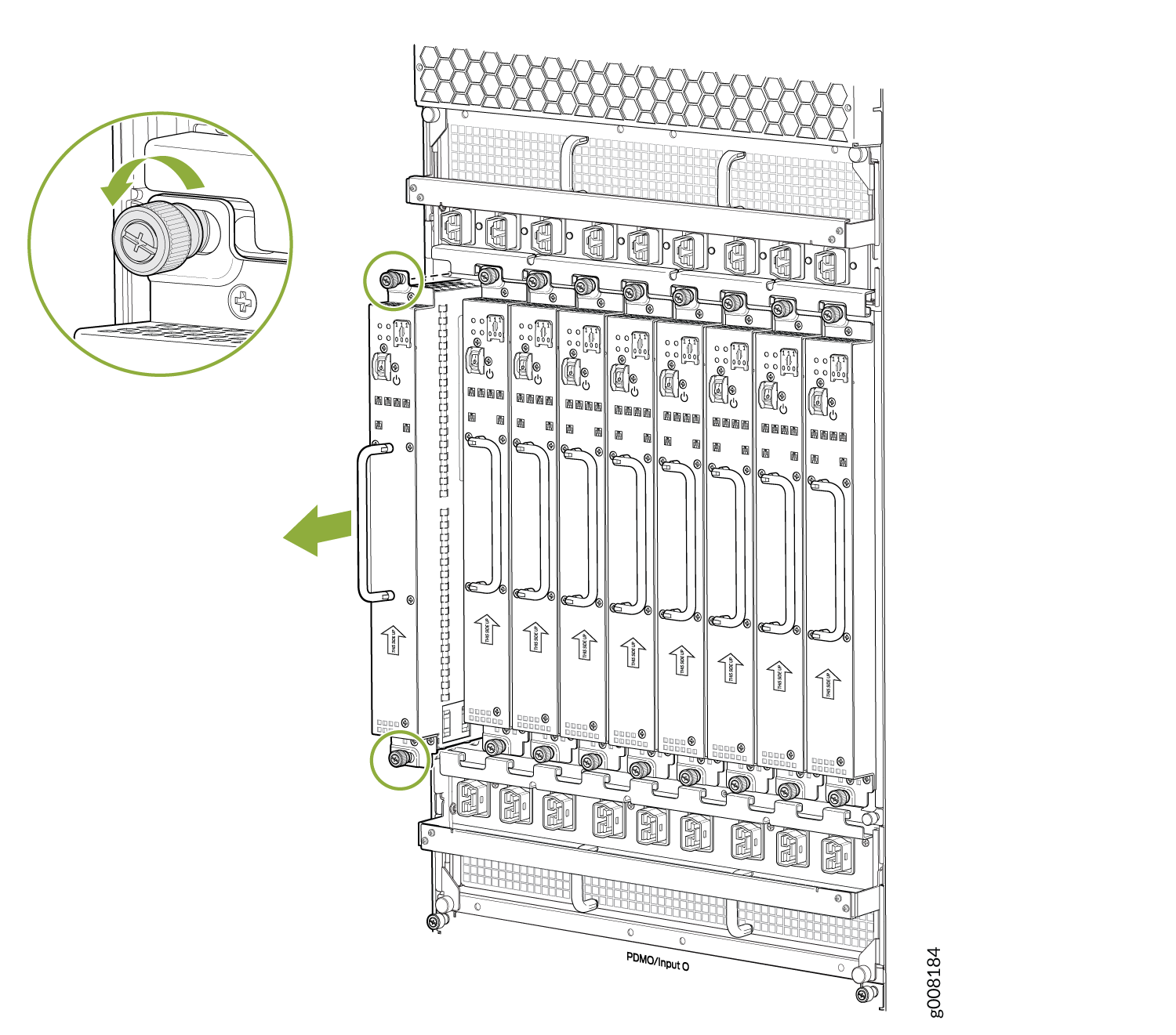
To remove a universal HVAC/HVDC PSM (see Figure 1, Figure 2, and Figure 3):

Note:

The minimum number of PSMs change, based on the configuration.

  1. With one PSM installed and operational, remove any additional PSM by turning the power switch to the off (O) position.
  2. Attach an electrostatic discharge (ESD) grounding strap to your bare wrist, and connect the strap to one of the ESD points on the chassis.
  3. Loosen the two captive screws on the PSM faceplate. Apply between 10 lb-in. (1.13 Nm) to 12 lb-in. (1.35 Nm) of torque to each screw. Do not overtighten the screws.
  4. While grasping the handle on the PSM faceplate with one hand, use your other hand to guide the PSM away from the chassis.
  5. Pull the PSM straight out of the chassis.
    Warning:

    To avoid damage, do not touch the power connectors in back of the PSM.

  6. Place the PSM module into an antistatic bag.
    Note:

    Each PSM slot not occupied by a universal (HVAC/HVDC) PSM must be covered by a PSM blank panel.

Figure 1: Removing an MX2020 Router Universal (HVAC/HVDC) Power Supply Module Removing an MX2020 Router Universal (HVAC/HVDC) Power Supply Module
Figure 2: Removing an MX2010 Router Universal (HVAC/HVDC) Power Supply Module Removing an MX2010 Router Universal (HVAC/HVDC) Power Supply Module
Figure 3: Removing an MX2008 Router Universal (HVAC/HVDC) Power Supply Module Removing an MX2008 Router Universal (HVAC/HVDC) Power Supply Module

Installing an MX2000 Router High-Voltage Universal (HVAC/HVDC) Power Supply Module

Before you install a universal (HVAC/HVDC) PSM, be aware of the following:

Note:

The universal (HVAC/HVDC) PSM is hot-swappable when a minimum number of PSMs installed and operational.

Depending on whether you are connecting to AC or DC power, these warnings apply to the universal HVAC/HVDC power distribution module (PDM):

Warning:

The DC PSMs have no circuit breakers that can physically disconnect DC current from the router. After DC feeds have been connected to the PDM, the DC voltage is always present on the power midplane and is distributed to the PSM connectors on the power midplane.

Warning:

The AC PSMs have no circuit breakers that can physically disconnect AC current from the router. After AC feeds have been connected to the PDM, the AC voltage is always present on the power midplane and is distributed to the PSM connectors on the power midplane.

CAUTION:

To maintain proper cooling and prevent thermal shutdown of the operating PSM, each PSM slot must contain either a PSM or a blank panel. If you remove a PSM, you must install a replacement PSM or a blank panel shortly after the removal.

Note:

After powering on a PSM, wait at least 60 seconds before turning it back off.

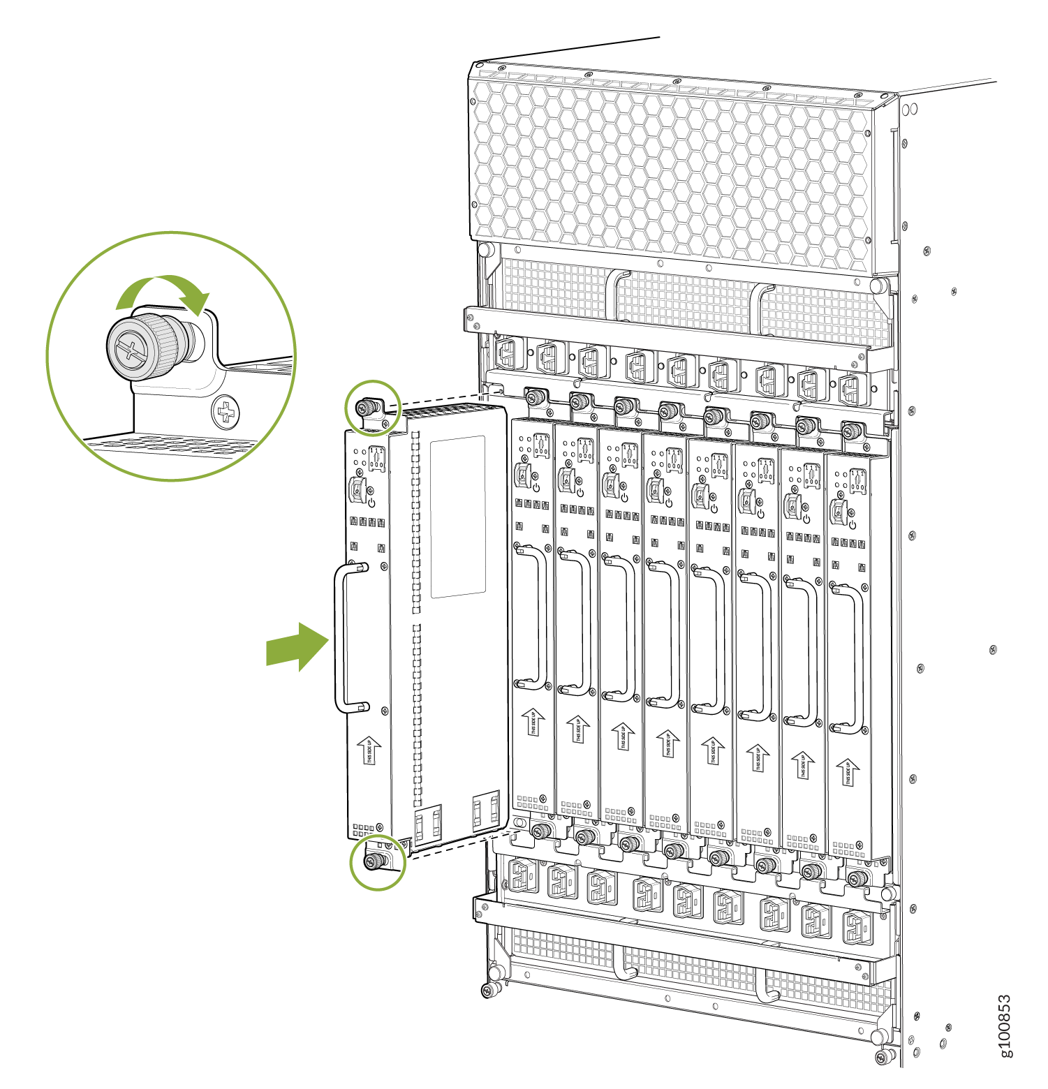
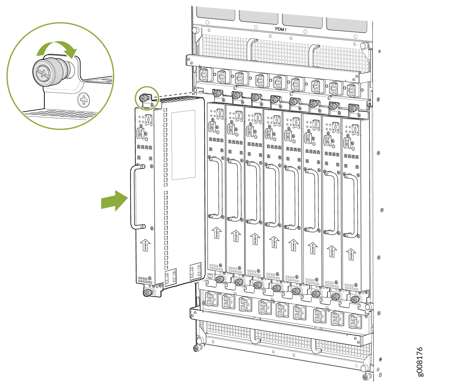
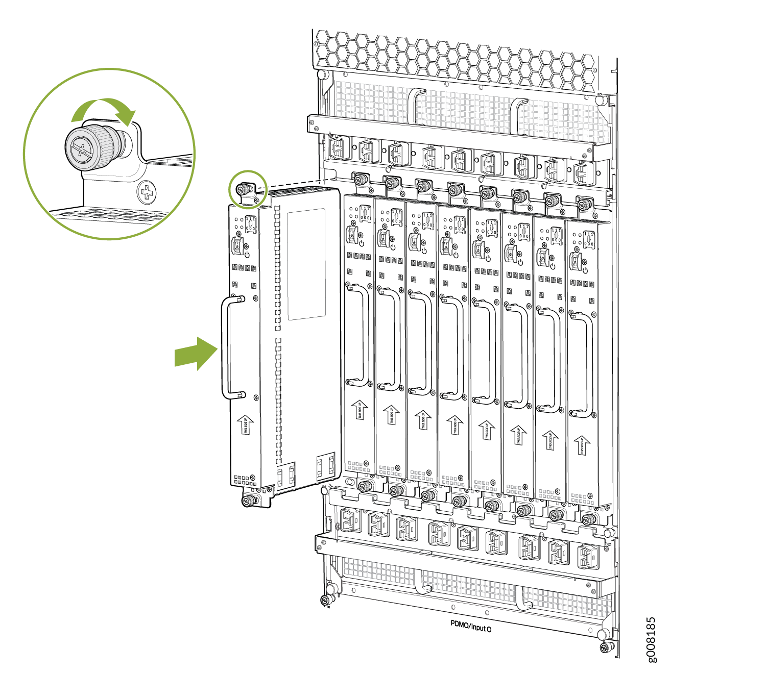
To install a universal (HVAC/HVDC) PSM (see Figure 4, Figure 5, and Figure 6):

  1. With one PSM installed and operational, install an additional PSM with the power supply switch in the off (O) or in the on (|) position.
    CAUTION:

    If there is only one PSM installed and operational, the power supply switch must be placed in the off (O) position.

  2. Attach an electrostatic discharge (ESD) grounding strap to your bare wrist, and connect the strap to one of the ESD points on the chassis.
  3. While grasping the handle on the PSM faceplate with one hand, use your other hand to guide the power supply module into the chassis.
  4. Tighten the captive screws on the PSM faceplate. Apply between 10 lb-in. (1.13 Nm) to 12 lb-in. (1.35 Nm) of torque to each screw. Do not overtighten the screws.
  5. Turn on the power switch to the on (|) position.
  6. Verify that the PWR OK LED is lit steadily green.
Figure 4: Installing an MX2020 Router Universal (HVAC/HVDC) Power Supply Module Installing an MX2020 Router Universal (HVAC/HVDC) Power Supply Module
Figure 5: Installing an MX2010 Router Universal (HVAC/HVDC) Power Supply Module Installing an MX2010 Router Universal (HVAC/HVDC) Power Supply Module
Figure 6: Installing an MX2008 Router Universal (HVAC/HVDC) Power Supply Module Installing an MX2008 Router Universal (HVAC/HVDC) Power Supply Module