MX2020 Cable Management Description
The MX2020 consists of a standard or extended cable management system.
Standard Cable Management System
The standard cable management system consists of the following components:
-
Upper cable manager—MX2000-CBL-TOP-S
-
Middle cable manager and air filter—MX2000-CBL-MID-S
-
Lower cable manager—MX2000-CBL-BTM-S
-
DC cable manager—MX2020-DC-CBL-MGR-S
-
Extended cable manager for the DC PDM (240 V China) and the Universal (HVAC/HVDC) PDM—MX2K-HV-CBL-MGR
The upper cable manager, (see Figure 1) is located just below the craft interface, has a removable cover that is secured by two captive screws with access to rows used for routing and securing the cables away from the front of the Modular Port Concentrators (MPCs), and Modular Interface Cards (MICs). The lower cable manager (see Figure 1) is located just below the bottom line card cage, has a removable cover that is secured by two captive screws with access to rows used for routing and securing the cables away from the front of the MPCs, and MICs, (see Figure 2).
You can use cable strips or other ties to gently secure the cables in the upper and lower cable manager. To secure the cables in place, loop the tie through the cable anchor and secure the tie.
Each DC PDM has one cable manager. The DC cable manager routes cables away from the rear of the PDMs (see Figure 1).
You can use cable strips or other ties to gently secure the cables in the DC cable manager. To secure the cables in place, loop the tie through the cable anchor and secure the tie. You can pull the DC cable manager up and outward to lock it into the maintenance position.
The middle card-cage cable manager, (see Figure 3 and Figure 4) is a combination cable tray and air filter located in the middle card cage, which has rows for routing and securing the cables away from the front of the CB-REs, and SFBs.
You can use cable strips or other ties to gently secure the cables in the middle cable manager. To secure the cables in place, loop the tie through the cable anchor and secure the tie. To access the air filter, the cable manager needs to be opened.
Extended Cable Management System
The extended cable management system consists of the following components:
-
Extended upper cable manager—MX2000-CBL-TOP-XT-S
-
Extended lower cable manager—MX2000-CBL-BTM-XT-S
-
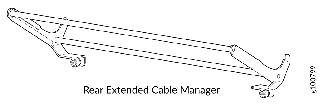
Extended DC cable manager—MX2020-DC-CBL-MGR-XT-S
The extended cable management system provides additional support to route and secure a large number of cables away from the front of the MPCs, and MICs (see Figure 5).
The extended DC cable management system provides additional support to route and secure a large number of cables away from the rear of the PDMs (see Figure 5 and Figure 6).
You can use cable strips or other ties to gently secure the cables in the upper and lower extended cable managers. To secure the cables in place, loop the tie through the cable anchor and secure the tie.