Replacing the MX2020 Cable Managers
The MX2020 router consists of an upper, middle card-cage, lower, and DC cable management system used for routing and securing cables away from system components. There are two types of cable management systems: standard and extended. The following instructions represent both.
The middle card-cage cable manager is permanently installed on the MX2020 system chassis, and cannot be removed.
Removing the MX2020 Upper Cable Manager
To accommodate additional clearance, you may order an extended upper cable manager from Juniper Networks.
To remove the upper cable manager (see Figure 1):
- Attach an electrostatic discharge (ESD) grounding strap to your bare wrist, and connect the strap to one of the ESD points on the chassis.
- Loosen the two captive screws on the upper cable manager cover, and remove it.
- Using a Phillips (+) screwdriver (number 1 or 2), loosen the mounting screws on the upper cable manager.
- Grasp the upper cable manager, and pull it straight out from the studs on the front of the chassis.
See Also
Removing the MX2020 Lower Cable Manager
To accommodate additional clearance, you may order an extended lower cable manager from Juniper Networks.
To remove the lower cable manager (see Figure 2):
- Attach an electrostatic discharge (ESD) grounding strap to your bare wrist, and connect the strap to one of the ESD points on the chassis.
- Loosen the two captive screws on the lower cable manager cover, and remove it.
- Using a Phillips (+) screwdriver (number 1 or 2), loosen the mounting screws on the lower cable manager.
- Grasp the lower cable manager, and pull it straight out from the studs on the front of the chassis.
See Also
Removing the MX2020 DC Cable Manager
To remove the standard DC cable manager (see Figure 3):
- Attach an electrostatic discharge (ESD) grounding strap to your bare wrist, and connect the strap to an approved site ESD grounding point. See the instructions for your site.
- Grasp the DC cable manager, lift up and pull straight out from the DC PDM on the rear of the chassis.
- Place the DC cable manager into an electrostatic bag and set it aside.
To remove the cable manager for the DC PDM (240 V China) and the universal (HVAC/HVDC) PDM (see Figure 4):
Attach an electrostatic discharge (ESD) grounding strap to your bare wrist, and connect the strap to an approved site ESD grounding point. See the instructions for your site.
Using a screwdriver, loosen the two screws on each side of the cable manager (see Figure 4
Figure 4: Removing the DC Cable Manager for DC PDM (240 V China) and the Universal (HVAC/HVDC) PDM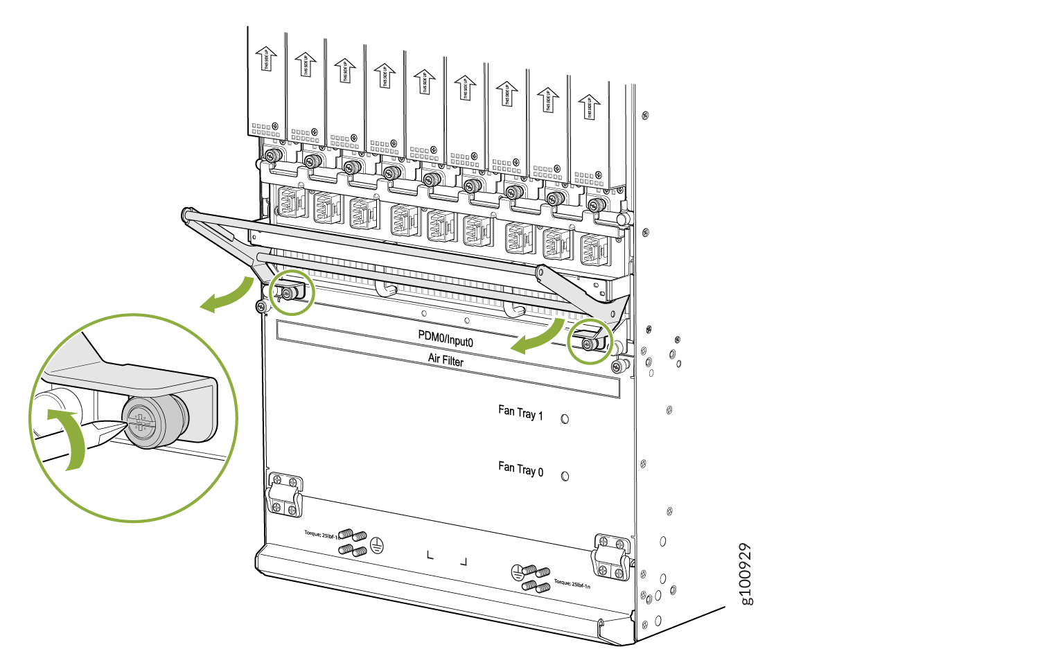
Grasp the DC cable manager, lift up and pull straight out from the DC PDM on the rear of the chassis.
Place the DC cable manager into an electrostatic bag and set it aside.
See Also
Installing the MX2020 Lower Cable Manager
To accommodate additional clearance, you may order an extended lower cable manager from Juniper Networks.
To install the lower cable manager (see Figure 5):
- Position the lower cable manager on the studs on the lower front of the chassis, just below the MPCs.
- Insert the screws into the corners in the lower cable manager onto the studs on the chassis.
- Using a Phillips (+) screwdriver (number 1 or 2), tighten the mounting screws securely.
- Replace the cable manager cover, and secure it with the two captive screws.
See Also
Installing the MX2020 Upper Cable Manager
To accommodate additional clearance, you may order an extended upper cable manager from Juniper Networks.
To install the upper cable manager (see Figure 6):
- Position the upper cable manager on the studs on the upper front of the chassis, just below the craft interface.
- Insert the screws into the corners in the upper cable manager onto the studs on the chassis.
- Using a Phillips (+) screwdriver (number 1 or 2), tighten the mounting screws securely.
- Replace the cable manager cover, and secure the two captive screws.
See Also
Installing the MX2020 DC Cable Manager
To accommodate additional clearance, you may order an extended DC cable manager from Juniper Networks.
To install the DC cable manager (see Figure 7):
- Attach an electrostatic discharge (ESD) grounding strap to your bare wrist, and connect the strap to one of the ESD points on the chassis.
- Position the DC cable manager over the two slots located on both sides of the DC PDM.
- Lift the DC cable manager slightly up while inserting the two flanges into the slots on both sides of the DC PDM.
- Push down to secure the DC cable manager in place.
To install the DC cable manager for the DC PDM (240 V China) or the universal (HVAC/HVDC) PDM (see Installing the MX2020 DC Cable Manager):
Attach an electrostatic discharge (ESD) grounding strap to your bare wrist, and connect the strap to one of the ESD points on the chassis.
Position the DC cable manager over the two slots located on both sides of the DC PDM.
Lift the DC cable manager slightly up while inserting the two flanges into the slots on both sides of the DC PDM.
Figure 8: Installing the DC Cable Manager on the DC PDM (240 V China) and Universal (HVAC/HVDC) PDM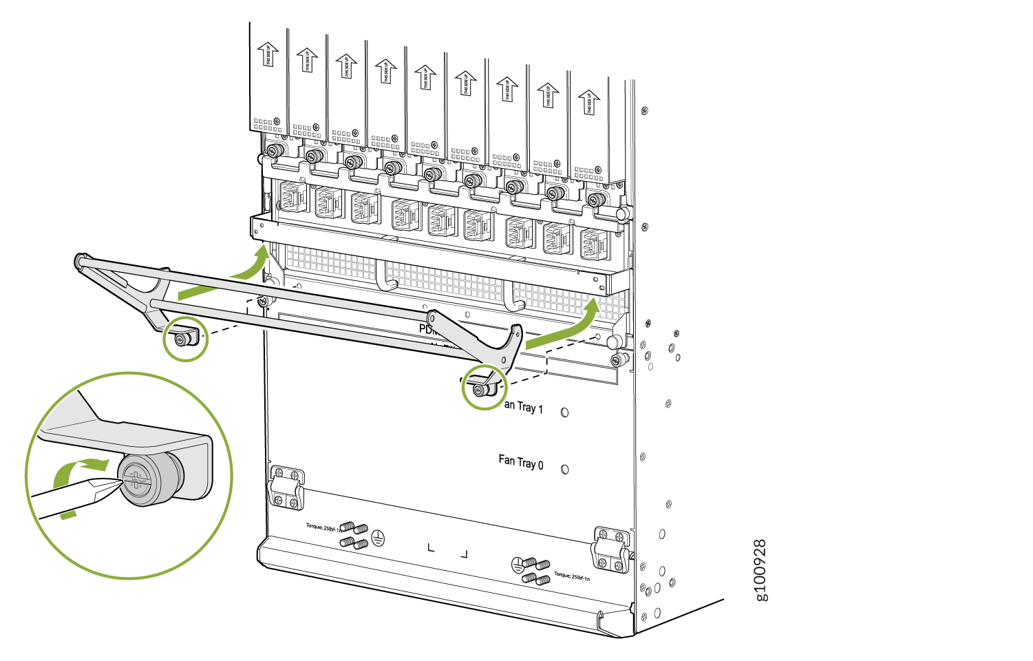
Push down to secure the DC cable manager in place. Tighten the screws using a screwdriver. See Figure 8.