ON THIS PAGE
Replacing the MX2020 Extended Cable Managers
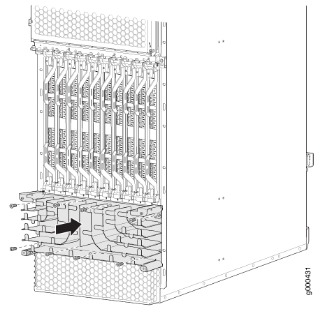
Removing the MX2020 Upper Extended Cable Manager
To remove the upper MX2020 extended cable manager:
- Attach an electrostatic discharge (ESD) grounding strap to your bare wrist, and connect the strap to one of the ESD points on the chassis.
- Remove the extended craft interface as described in Removing the MX2020 Extended Craft Interface.
- To remove the cover, loosen the two captive screws on the extended cable manager cover. Set the extended cable manager cover aside.
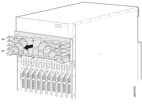
- Remove the eight screws that secure the extended cable manager to the chassis as shown in Figure 1.
- Pull the extended cable manager away from the chassis.
Figure 1: Removing the Extended Upper Cable Manager
Removing the MX2020 Lower Extended Cable Manager
To remove the lower MX2020 extended cable manager:
- Attach an electrostatic discharge (ESD) grounding strap to your bare wrist, and connect the strap to one of the ESD points on the chassis.
- To remove the cover, loosen the two captive screws on the extended cable manager cover. Set the extended cable manager cover aside.
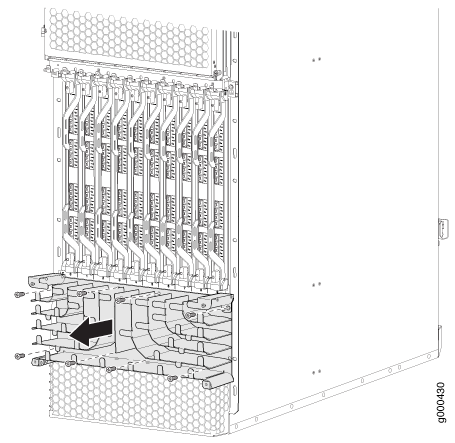
- Remove the eight screws that secure the extended cable manager to the chassis as shown in Figure 2.
- Pull the extended cable manager away from the chassis.
Figure 2: Removing the Extended Lower Cable Manager
Removing the MX2020 Extended DC Cable Manager
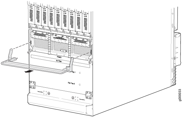
To remove the extended DC cable manager (see Figure 3):
- Attach an electrostatic discharge (ESD) grounding strap to your bare wrist, and connect the strap to one of the ESD points on the chassis.
- Using a Phillips (+) screwdriver (number 1 or 2), loosen the two captive screws on the DC cable manager.
- Grasp the extended DC cable manager, lift up and pull straight out from the DC PDM on the rear of the chassis.
- Place the extended DC cable manager into an electrostatic bag and set it aside.
Figure 3: Removing the Extended
DC Cable Manager
Installing the MX2020 Upper Extended Cable Manager
The upper extended cable manager should be used with the extended craft interface to allow for additional clearance.
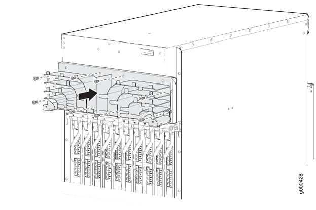
To install the upper extended cable manager (see Figure 4):
- Attach an electrostatic discharge (ESD) grounding strap to your bare wrist, and connect the strap to one of the ESD points on the chassis.
- If necessary, remove the extended craft interface as described in Removing an MX2020 Extended Craft Interface.
- Position the upper extended cable manager on the studs below the location of the craft interface.
- Attach the upper extended cable manager using eight screws as shown in Figure 4.
- Replace the cable manager cover, and secure it with the two captive screws.
- Install the extended craft interface as described in Installing an MX2020 Extended Craft Interface.
Figure 4: Installing
the MX2020 Upper Extended Cable Manager
Installing the Lower MX2020 Extended Cable Manager
To install the lower extended cable manager (see Figure 5):
- Attach an electrostatic discharge (ESD) grounding strap to your bare wrist, and connect the strap to one of the ESD points on the chassis.
- Position the lower extended cable manager on the studs below the lower card cage.
- Attach the lower extended cable manager using eight screws as shown in Figure 5.
- Replace the cable manager cover, and secure it with the two captive screws.
Figure 5: Installing
the Extended Lower Cable Manager
Installing the MX2020 Extended DC Cable Manager
To install the extended DC cable manager (see Figure 6):
- Attach an electrostatic discharge (ESD) grounding strap to your bare wrist, and connect the strap to one of the ESD points on the chassis.
- Position the extended DC cable manager over the two slots located on both sides of the DC PDM.
- Lift the extended DC cable manager slightly up while inserting the two flanges into the slots on both sides of the DC PDM.
- Push the extended DC cable manager into place.
- Tighten the two captive screws to secure the extended DC cable manager.
Figure 6: Installing the Extended
DC Cable Manager
