MX2020 DC Power Distribution (240 V China) Description
Most sites distribute DC power through a main conduit that leads to frame-mounting DC power distribution panels, one of which might be located at a location near the rack that houses the router. The 240 V China PDM cable connects the PDM to the power distribution panel and safety ground connection.
The PSMs can be connected to two separate feeds from different sources that are used for feed redundancy. There are up to four PDMs located in slots PDM0/Input0, PDM2/Input0, PDM1/Input1, and PDM3/Input1. Each feed (feed A or feed B) is connected from one source to one PDM and feeds from the other source to the second PDM of the DC power system. This configuration balances power draw for the system using the commonly deployed A/B feed redundancy.
Each subsystem provides N+1 PSM redundancy along with N+N feed redundancy. If both DC feeds are available, operating power draws from the feed with higher voltage.
Depending on the voltage of the DC feeds, power can be drawn from both feeds. The feed with higher voltage provides more power. If the difference between the voltages is sufficient, then the higher voltage feed provides all the power. When the voltages are exactly the same, equal power is drawn from both feeds.
Each set of power cables powers a single DC PSM and is capable of delivering 2500 W of power. If feeds that connect to one PDM fail in a redundant configuration, the other feed provides full power.
Figure 1 shows a typical DC source cabling arrangement.
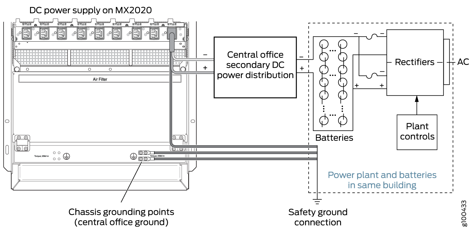
All DC PSMs in a subsystem share the load (nine PSMs on the top half share the load, as well as the nine PSMs on the bottom share the load). If one PSM fails in a redundant configuration, the remaining PSMs provide power to FRUs. Up to eighteen PSMs may be required to supply power to a fully configured router. Nine PSMs in the lower card cage supply power to the two CB-REs (active and redundant), eight SFBs, lower ten MPCs, two lower fan trays and one fan tray on the top half. Nine PSMs in the upper card cage supply power to the two upper fan trays, upper ten MPCs, two CB-REs (active and redundant), eight SFBs, and a fan tray in the lower card cage. A portion of power from each zone is reserved to power critical FRUs. These FRUs allow the system to operate even if power to a complete zone fails.
For more information, see Determining DC Power Requirements for Your MX2020 Router.
You must ensure that power connections maintain the proper polarity. The power source cables might be labeled (+) and (-) to indicate their polarity. There is no standard color coding for DC power cables. The color coding used by the external DC power source at your site determines the color coding for the leads on the power cables that attach to the 240 V China PDM power cable.
The two input sources must have similar grounding type because the PSM can see 480 V if one source has positive ground (-240 V), and the other source has negative ground (+240 V). This might damage the PSM.
For field-wiring connections, use copper conductors only.
Power cords and cables must not block access to device components or drape where people could trip on them.