Replacing an MX2000 Three-Phase Delta AC Power Distribution Module
Removing an MX2000 Three-Phase Delta AC Power Distribution Module
Before you remove a three-phase delta AC PDM, be aware of the following:
Before performing AC power procedures, disconnect all power sources. To ensure that all power is OFF, locate the circuit breaker on the panel board that services the AC circuit, switch the circuit breaker to the OFF position, and tape the switch handle of the circuit breaker in the OFF position.
Do not touch the power connectors on the PDM. They can contain dangerous voltages.
To maintain proper cooling and prevent thermal shutdown of the operating power supply unit, each PDM slot must contain either a PDM or a blank panel. If you remove a PDM, you must install a replacement PDM or a blank panel shortly after the removal.
After powering off a PDM, wait at least 60 seconds before turning the circuit breaker to the ON position.
The MX2008, MX2010, and MX2020 routers support the same power modules (AC/DC PSMs and AC/DC PDMs).
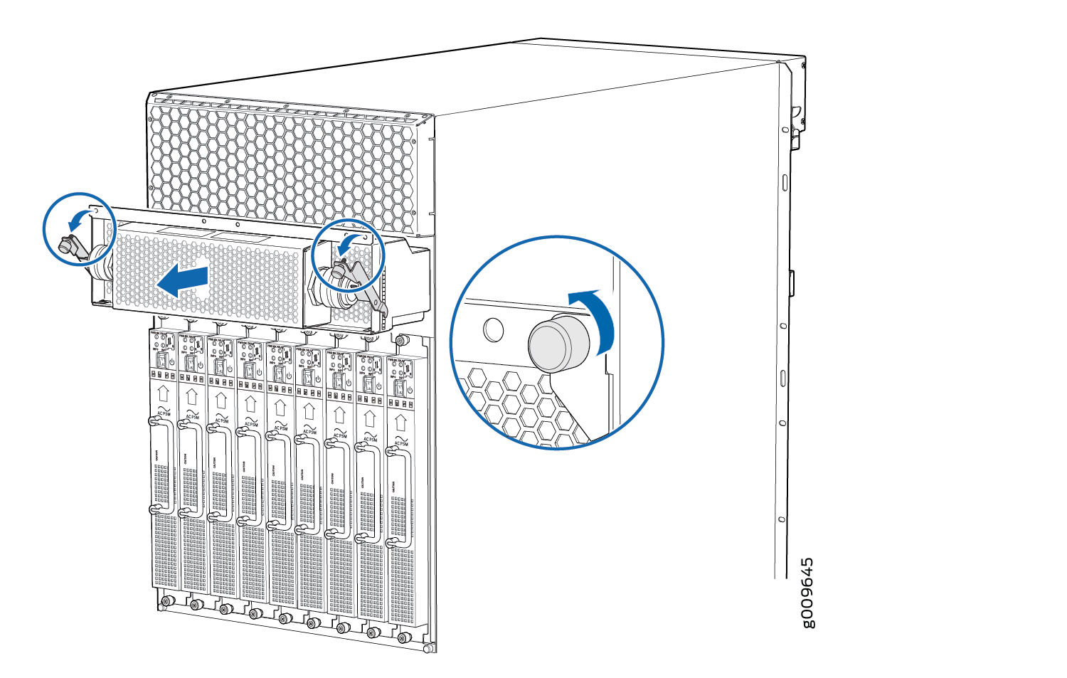
To remove a three-phase delta AC PDM:
- Disconnect the AC power cord (see Figure 1) from the power source.Figure 1: Three-Phase Delta AC Power Cord
- Disconnect the wires from the AC terminal block on the
three-phase delta AC PDM (see Figure 2), loosen each
of the input terminals or grounding
point screws, and remove each wire
form the grounding point or input terminal.
To remove wires from the terminal block that serves six PSMs:
Remove the wire labeled L3 from the input terminal labeled C1.
Remove the wire labeled L2 from the input terminal labeled B1.
Remove the wire labeled L1 from the input terminal labeled A1.
Remove the grounding wire from the grounding point labeled GND.
Figure 2: Disconnecting the Power Cord from a Three-Phase Delta AC Power Distribution Module
To remove wires from the terminal block that serves three PSMs:
Remove the wire labeled L3 from the input terminal labeled C2.
Remove the wire labeled L2 from the input terminal labeled B2.
Remove the wire labeled L1 from the input terminal labeled A2.
Remove the grounding wire from the grounding point labeled GND.
Note:The three-phase delta AC PDM terminal blocks will be flipped depending on which slot the PDM gets plugged into.
Note:The color of each AC power wire might vary. The MX2000 chassis is not sensitive to phase rotation sequence—either clockwise or counterclockwise will operate correctly.
Note:The terminal connections have either slotted screws or hex screws. Use a 1/4-in. slotted screwdriver for the slotted screws. Use a 5/32-in. (4 mm) Allen wrench for the 5/16-in. hex screws.
Each PDM slot not occupied by a AC PDM must be covered by a PDM blank panel.
See Also
Installing an MX2000 Router Three-Phase Delta AC Power Distribution Module
Before you install a three-phase delta AC power distribution module (PDM), be aware of the following:
Before performing AC power procedures, disconnect all power sources. To ensure that all power is off, locate the circuit breaker on the panel board that services the AC circuit, switch the circuit breaker to the off position, and tape the switch handle of the circuit breaker in the off position.
To maintain proper cooling and prevent thermal shutdown of the operating power supply unit, each PDM slot must contain either a PDM or a blank panel. If you remove a PDM, you must install a replacement PDM or a blank panel shortly after the removal.
After powering off a PDM, wait at least 60 seconds before turning the circuit breaker back on.
The PDMs are hot swappable in a redundant configuration. However, you cannot switch from one type of PDM (AC or DC) to another while the system is on.
Each three-phase delta AC PDM weighs approximately 12 lb (5.44 kg). To install a three-phase delta AC PDM:
- Using a number 2 Phillips (+) screwdriver, loosen the
four screws on the cover of the metal wiring compartment that protects
the AC terminal block.Figure 6: Installing a Three-Phase Delta AC Power Distribution Module (MX2020)
 Figure 7: Installing a Three-Phase Delta AC Power Distribution Module (MX2010)
 Figure 8: Installing a Three-Phase Delta AC Power Distribution Module (MX2008)
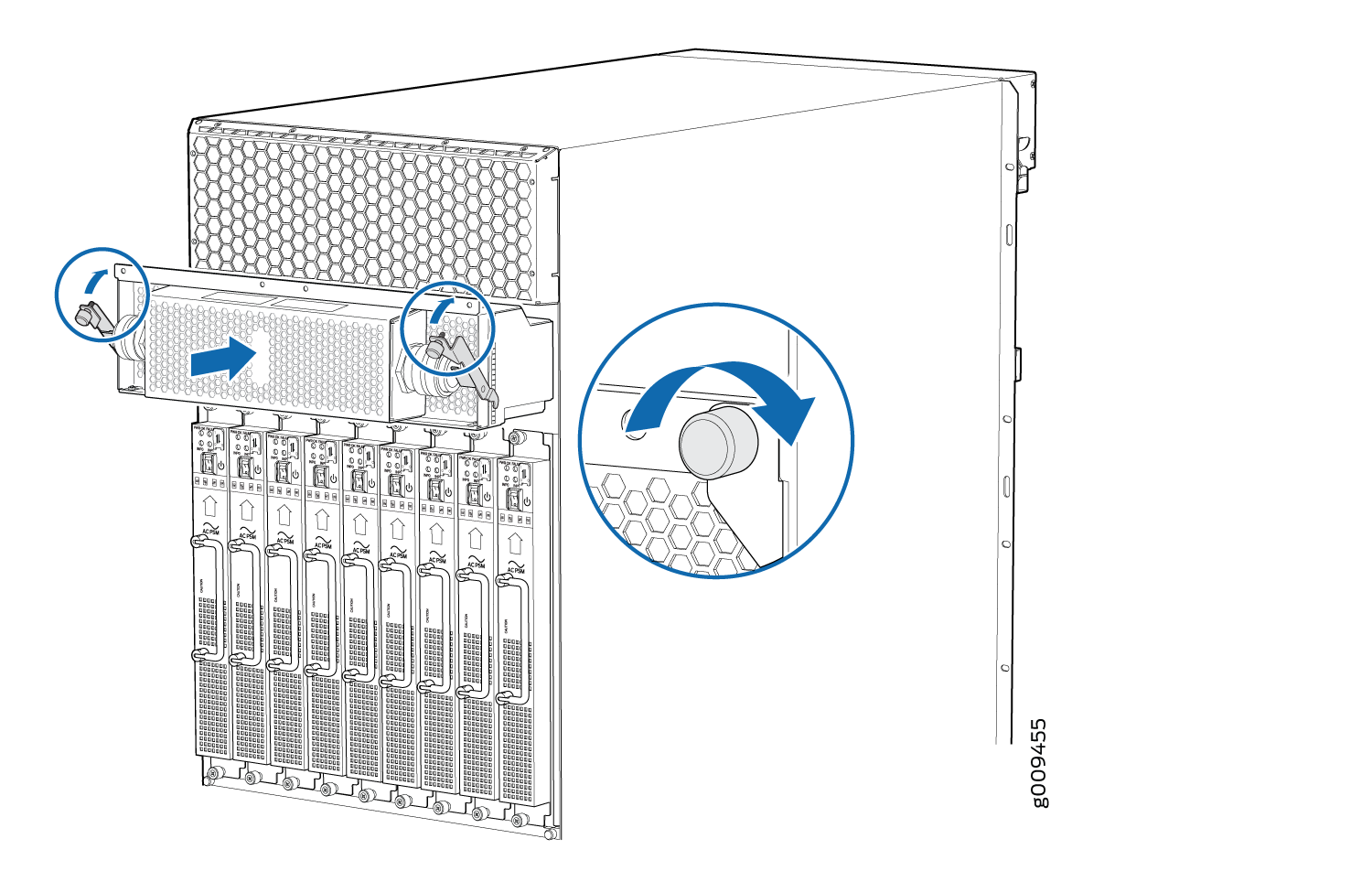
- Connect the wires to the AC terminal block on the three-phase
delta AC PDM (see Figure 9). Loosen each of the input terminals or grounding point screws,
and insert the wire into the grounding point or input terminal, and
tighten the screw (see Table 1 for approved AC wire gauge).
To insert wires into the terminal block that serves six PSMs:
Insert the grounding wire into the grounding point labeled GND.
Insert the wire labeled L1 into the input terminal labeled A1.
Insert the wire labeled L2 into the input terminal labeled B1.
Insert the wire labeled L3 into the input terminal labeled C1.
Figure 9: Connecting Power to a Three-Phase Delta AC Power Distribution ModuleNote:The three-phase delta AC PDM terminal blocks will be flipped depending on which slot the PDM gets plugged into.
Note:The color of each AC power wire might vary. The MX2000 chassis is not sensitive to phase rotation sequence—either clockwise or counterclockwise will operate correctly.
CAUTION:Wire label configuration is for Juniper Networks supplied cable only. If you are using your own cable, make sure you use the proper connections.
To insert wires into the terminal block that serves three PSMs:
Insert the grounding wire into the grounding point labeled GND.
Insert the wire labeled L1 into the input terminal labeled A2.
Insert the wire labeled L2 into the input terminal labeled B2.
Insert the wire labeled L3 into the input terminal labeled C2.
Note:The terminal connections have either slotted screws or hex screws. Use a 1/4-in. slotted screwdriver for the slotted screws. Use a 5/32-in. (4 mm) Allen wrench for the 5/16-in. hex screws.
Warning:To protect power supplies from input voltage that might be caused by mis-wired PDMs, before reinstalling the metal cover to the wiring compartment, apply AC voltage to the PDM (with the PSM power switch turned off). Verify that the two LEDs on the PDM are lit green and that the AC voltage between AC terminal blocks A1-B1, B1-C1, C1-A1, A2-B2, B2-C2, and C2-A2 for three-phase delta PDM is not more than 264 VAC when measured with a digital voltage meter (DVM). Then turn off the AC breaker to remove power from the PDM and install the metal cover.
Note:Three-phase delta AC wire assembly kits can be purchased from Juniper Networks.
Table 1: Supported Three-Phase Delta AC Wire Gauge Wire Gauge Description 4 x 6-AWG or equivalent
4 conductor wires, each wire is 6-AWG
Note:We recommend that you use the proper gauge wire in order for the cable clamps to hold the AC cables. Using smaller gauge wiring will result in the cable clamps not tightening properly.
Warning:Power connections must be performed by a licensed electrician only.