ON THIS PAGE
Connect AC Power to an MX2008 Router with Three-Phase Delta AC Power Distribution Modules
Connecting AC Power to an MX2000 Router with Three-Phase Wye AC Power Distribution Modules
Connecting Power to an MX2000 Single-Phase AC Power Distribution Module
Connect Power to a Single-Phase Seven-Feed AC Power Distribution Module
Connecting the MX2008 to AC Power
Installing an MX2008 Three-Phase Wye AC Power Cord
To install a three-phase wye AC power cord:
- Connect the wires to the AC terminal block on the three-phase
delta AC PDM (see Figure 1).
Loosen each of the input terminal or grounding point screws, and insert
the wire into the grounding point or input terminal, and tighten the
screw (see Table 1 for approved
AC wire gauge).
To insert wires into the terminal block that serves six PSMs:
Insert the grounding wire into the grounding point labeled GND.
Insert the wire labeled L1 into the input terminal labeled A1.
Insert the wire labeled L2 into the input terminal labeled B1.
Insert the wire labeled L3 into the input terminal labeled C1.
Insert the wire labeled N into the input terminal labeled N1.
Figure 1: Connecting Power to a Three-Phase Wye AC Power Distribution Module Note:
Note:The three-phase wye AC PDM terminal blocks will be flipped depending on which slot the PDM gets plugged into.
Note:The color of each AC power wire might vary. The MX2008 chassis is not sensitive to phase rotation sequence—either CW or CCW will operate correctly.
CAUTION:Wire label configuration is for Juniper Networks supplied cable only. If using your own cable, make sure you use the proper connections.
To insert wires into the terminal block that serves three PSMs:
Insert the grounding wire into the grounding point labeled GND.
Insert the wire labeled L1 into the input terminal labeled A2.
Insert the wire labeled L2 into the input terminal labeled B2.
Insert the wire labeled L3 into the input terminal labeled C2.
Insert the wire labeled N into the input terminal labeled N2.
Note:The terminal connections have either slotted screws or hex screws. Use a 1/4-in. slotted screwdriver for the slotted screws. Use a 5/32-in. (4 mm) Allen wrench for the 5/16-in. hex screws.
Warning:To protect power supplies from input voltage that may be caused by mis-wired PDMs, before reinstalling the metal cover to the wiring compartment apply AC voltage to the PDM (with disengaged PSM) to make sure that two LEDs on the PDM are lit green and that the AC voltage between AC terminal blocks A1-N1, B1-N1, C1-N1, A2-N2, B2-N2, and C2-N2 for three-phase wye PDM is not more than 264 VAC when measured with a DVM. Then turn off the AC breaker de-energizing the PDM and install the metal cover and engage all AC PSMs.
Note:Three-phase wye AC wire assembly kits can be purchased from Juniper Networks.
Table 1: Supported Three-Phase Wye AC Wire Gauge Wire Gauge Description 5 x 10-AWG or equivalent
5 conductor wires, each wire is 10-AWG
Note:We recommend that you use the proper gauge wire in order for the cable clamps to hold the AC cables. Using smaller gauge wiring will result in the cable clamps not tightening properly.
Warning:Power connections must be performed by a licensed electrician only.
See Also
Installing MX2008 AC Power Supply Modules
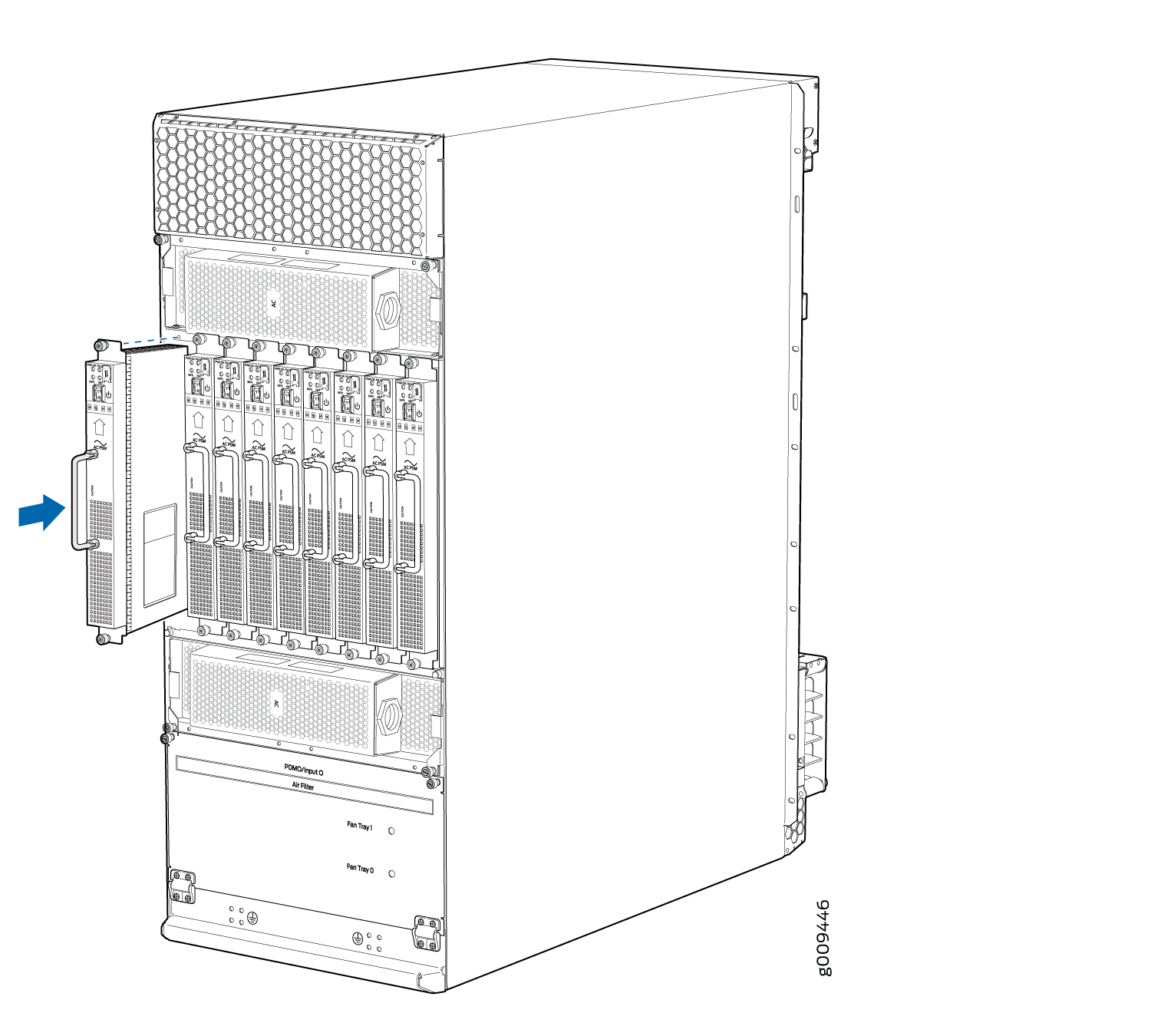
To install an MX2008 AC PSM:
- On the PSM, slide the plastic cover away from the input
mode switch to expose the dual DIP switches. Move the input mode DIP
switch to the on or off position for the desired power supply feed
configuration (see Figure 2). For available switch positions on the AC PSM, see MX2000 AC Power Supply Module Description.Note:
The DIP switches are used only to indicate presence of a feed. If both feeds are present, power is always drawn from feed 0. Power will be drawn from feed 1 only if feed 0 fails. A PSM failure triggers the alarm LED on the craft interface.
Figure 2: Selecting AC Power System Feed Redundancy
- Using both hands, grasp the handle and slide the PSM straight
into the chassis until the PSM is fully seated in the chassis slot.
Tighten the two captive screws (see Figure 3).Figure 3: MX2008 Router with AC Power Supply Modules Installed
- Repeat Steps 1 through 7 for installing PSMs in slots 0, 1, and 2,
where required.Figure 4: MX2008 AC Power Supply Module Front View
 Note:
Note:Each PSM slot not occupied by a AC PSM must be covered by a PSM blank panel.
Connect AC Power to an MX2008 Router with Three-Phase Delta AC Power Distribution Modules
Do not mix AC and DC power modules within the same router.
Power connections must be performed by a licensed electrician only.
The MX2008, MX2010, and MX2020 routers support the same power modules (AC/DC PSMs and AC/DC PDMs).
You connect AC power to the router with three-phase delta AC power distribution modules (PDMs) by connecting the AC power cord from an AC PDM to an AC power source.
To connect an AC power cord to an AC power source:
- Connect the wires to the AC terminal block on the three-phase
delta AC PDM (see Figure 5). Loosen the input terminal or grounding point screw, insert
each wire into the grounding point input terminal, and tighten the
screw (see Table 2 for approved
AC wire gauge).Note:
The terminal connections have either slotted screws or hex screws. Use a 1/4-in. slotted screwdriver for the slotted screws. Use a 5/32-in. (4 mm) Allen wrench for the 5/16-in. hex screws.
To connect wires to the terminal block that serves six PSMs:
Insert the grounding wire into the grounding point labeled GND.
Insert the wire labeled L1 into the input terminal labeled A1.
Insert the wire labeled L2 into the input terminal labeled B1.
Insert the wire labeled L3 into the input terminal labeled C1.
Figure 5: Connecting Power to a Three-Phase Delta AC Power Distribution Module Note:
Note:The three-phase delta AC PDM terminal blocks will be flipped depending on which slot the PDM gets plugged into.
Note:The color of each AC power wire might vary. The MX2008 chassis is not sensitive to phase rotation sequence—either CW or CCW will operate correctly.
CAUTION:Wire label configuration is for Juniper Networks supplied cable only. If you are using your own cable, make sure you use the proper connections.
To connect wires to the terminal block that serves three PSMs:
Insert the grounding wire into the grounding point labeled GND.
Insert the wire labeled L1 into the input terminal labeled A2.
Insert the wire labeled L2 into the input terminal labeled B2.
Insert the wire labeled L3 into the input terminal labeled C2.
Warning:To protect power supplies from input voltage that might be caused by mis-wired PDMs, before reinstalling the metal cover to the wiring compartment apply AC voltage to the PDM (with disengaged PSM) make sure that two LEDs on the PDM are lit green and that the AC voltage between AC terminal blocks A1-B1, B1-C1, C1-A1, A2-B2, B2-C2, and C2-A2 for three-phase delta PDM is not more than 264 VAC when measured with a digital voltage meter (DVM). Then turn off the AC breaker, de-energizing the PDM, and install the metal cover and engage all AC PSMs.
Note:The terminal connections have either slotted screws or hex screws. Use a 1/4-in. slotted screwdriver for the slotted screws. Use a 5/32-in. (4 mm) Allen wrench for the 5/16-in. hex screws
Note:Three-phase delta AC wire assembly kits can be purchased from Juniper Networks.
Table 2: Supported Three-Phase Delta AC Wire Gauge Wire Gauge Description 4 x 6-AWG or equivalent
4 conductor wires, each wire is 6-AWG
Note:We recommend that you use the proper gauge wire in order for the cable clamps to hold the AC cables. Using smaller gauge wiring results in the cable clamps not tightening properly.
Warning:Power connections must be performed by a licensed electrician only.
Connecting AC Power to an MX2000 Router with Three-Phase Wye AC Power Distribution Modules
Do not mix AC and DC power modules within the same router.
Power connections must be performed by a licensed electrician only.
To connect an AC power cord to an AC power source:
- Connect the wires to the AC terminal block on the three-phase
wye AC PDM (see Figure 6). Loosen the input terminal or grounding point screw, insert each
wire into the grounding point or input terminal, and tighten the screw
(see Table 3 for approved AC wire
gauge).Note:
The terminal connections have either slotted screws or hex screws. Use a 1/4-in. slotted screwdriver for the slotted screws. Use a 5/32-in. (4 mm) Allen wrench for the 5/16-in. hex screws.
To connect wires to the terminal block that serves six PSMs:
Insert the grounding wire into the grounding point labeled GND.
Insert the wire labeled L1 into the input terminal labeled A1.
Insert the wire labeled L2 into the input terminal labeled B1.
Insert the wire labeled L3 into the input terminal labeled C1.
Insert the wire labeled N into the input terminal labeled N1.
Figure 6: Connecting Power to a Three-Phase Wye AC Power Distribution ModuleNote:The three-phase wye AC PDM terminal blocks will be flipped depending on which slot the PDM gets plugged into.
Note:The color of each AC power wire might vary. The MX2000 series chassis is not sensitive to phase rotation sequence—either CW or CCW will operate correctly.
CAUTION:Wire label configuration is for Juniper Networks supplied cable only. If using your own cable, make sure you use the proper connections.
To connect wires to the terminal block that serves three PSMs:
Insert the grounding wire into the grounding point labeled GND.
Insert the wire labeled L1 into the input terminal labeled A2.
Insert the wire labeled L2 into the input terminal labeled B2.
Insert the wire labeled L3 into the input terminal labeled C2.
Insert the wire labeled N into the input terminal labeled N2.
Warning:To protect power supplies from input voltage that might be caused by mis-wired PDMs, before reinstalling the metal cover to the wiring compartment, apply AC voltage to the PDM (with disengaged PSM) and make sure that two LEDs on the PDM are lit green and that the AC voltage between AC terminal blocks A1-N1, B1-N1, C1-N1, A2-N2, B2-N2, and C2-N2 for three-phase wye PDM is not more than 264 VAC when measured with a digital voltage meter (DVM). Then turn off the AC breaker, de-energizing the PDM, and install the metal cover and engage all AC PSMs.
Note:Three-phase wye AC wire assembly kits can be purchased from Juniper Networks.
Table 3: Supported Three-Phase Wye AC Wire Gauge Wire Gauge Description 5 x 10-AWG or equivalent
5 conductor wires, each wire is 10-AWG
Note:We recommend that you use the proper gauge wire in order for the cable clamps to hold the AC cables. Using smaller gauge wiring will result in the cable clamps not tightening properly.
Warning:Power connections must be performed by a licensed electrician only.
Connecting Power to an MX2000 Single-Phase AC Power Distribution Module
Do not mix AC and DC power distribution modules (PDMs) within the same router.
The MX2008, MX2010, and MX2020 routers support the same power modules (AC/DC PSMs and AC/DC PDMs).
To connect an AC power cord to a single-phase seven-feed or nine-feed AC power distribution module (PDM):
- Plug the power cords into the power sockets on the PDM.
see Figure 7. Apply slight pressure so
that the power cords are firmly seated in the power socket. As you
plug in each power cord, the power LED for the socket lights up green.Figure 7: Plugging into the MX2008 Single-Phase AC Power Distribution Module
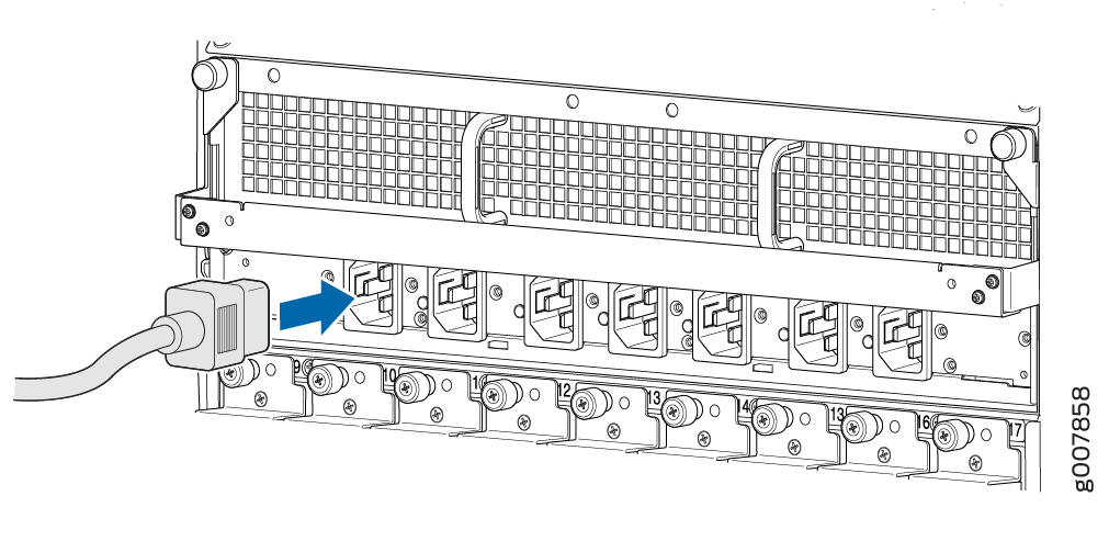
Do not touch the power connectors on the PDM. They can contain dangerous voltages.
See Also
Connect Power to a Single-Phase Seven-Feed AC Power Distribution Module
Do not mix AC and DC power distribution modules (PDMs) within the same router.
To connect an AC power cord to an AC power source:
- Attach an electrostatic discharge (ESD) grounding strap to your bare wrist, and connect the strap to an approved site ESD grounding point. See the instructions for your site.
- Switch off the dedicated customer site circuit breakers. Ensure that the voltage across the AC power source cable leads is 0 V and that there is no chance that the cable leads might become active during installation.
- Detach the ESD grounding strap from the approved site ESD grounding point, and connect the strap to one of the ESD points on the chassis.
- Switch off (O) the AC power supply modules (PSMs) and disengage all AC PSMs.
- Move the safety retention bar downwards and tight the captive retention screws.
- Connect the powers cords to the AC PDM.
- Verify that the power cords are not touching or blocking access to router components, and that it does not drape where people could trip on it.
Do not touch the power connectors on the PDM. They can contain dangerous voltages.
Powering On a Three-Phase AC-Powered MX2000 Router
You can use this procedure for a router with either a three-phase delta AC power distribution module (PDM) or a three-phase wye AC PDM.