Replacing a CFP2 Transceiver
Removing a CFP2 Transceiver
C form-factor pluggables (CFPs) are transceivers that can be removed from a PIC. CFP2 transceivers are hot-insertable and hot-removable. Removing a CFP2 transceiver does not interrupt PIC functioning, but the removed CFP2 transceiver no longer receives or transmits data.
To remove a CFP2 transceiver (see Figure 1):
- Place an electrostatic bag or antistatic mat on a flat, stable surface to receive the CFP transceiver. Have ready a rubber safety cap for the CFP2 transceiver and the cable.
- Attach an electrostatic discharge (ESD) grounding strap to your bare wrist, and connect the strap to one of the ESD points on the chassis.
- Label the cable connected to the CFP2 transceiver so that you can later reconnect it to the correct CFP2 transceiver.
- Disconnect the cable from the CFP2 transceiver. Immediately
cover the transceiver and the end of the cable with a rubber safety
cap.Laser Warning:
Do not look directly into a fiber-optic transceiver or into the ends of fiber-optic cables. Fiber-optic transceivers and fiber-optic cable connected to a transceiver emit laser light that can damage your eyes.
CAUTION:Do not leave a fiber-optic transceiver uncovered except when inserting or removing cable. The safety cap keeps the port clean and prevents accidental exposure to laser light.
- Arrange the cable in the cable management system to prevent
it from dislodging or developing stress points. Secure the cable so
that it is not supporting its own weight as it hangs to the floor.
Place excess cable out of the way in a neatly coiled loop in the cable
management system. Placing fasteners on the loop helps to maintain
its shape.CAUTION:
Avoid bending fiber-optic cable beyond its minimum bend radius. An arc smaller than a few inches in diameter can damage the cable and cause problems that are difficult to diagnose.
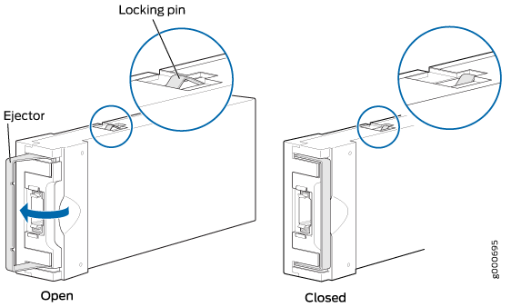
- Pull the ejector latch to the extreme end away from the
CFP2 transceiver faceplate to unseat the CFP2 transceiver from the
PIC. Pull the CFP2 transceiver out of the PIC and place it on the
antistatic mat or in the electrostatic bag.Note:
You cannot remove the transceiver until you move the ejector latch to the extreme end.
Installing a CFP2 Transceiver
To install a replacement CFP2:
- Attach an electrostatic discharge (ESD) grounding strap to your bare wrist, and connect the strap to one of the ESD points on the chassis.
- Verify that a rubber safety cap covers the CFP transceiver, installing one if necessary.
- Orient the CFP2 over the port in the PIC so that the connector end will enter the slot first and the CFP2 connector faces the appropriate direction.
- Slide the CFP2 into the slot. If there is resistance, remove the CFP2 and flip it so that the connector faces the other direction.
- Remove the rubber safety cap from the transceiver and
the end of the cable, and insert the cable into the transceiver.Laser Warning:
Do not look directly into a fiber-optic transceiver or into the ends of fiber-optic cables. Fiber-optic transceivers and fiber-optic cable connected to a transceiver emit laser light that can damage your eyes.
CAUTION:Do not leave a fiber-optic transceiver uncovered except when inserting or removing cable. The safety cap keeps the port clean and prevents accidental exposure to laser light.
- Arrange the cable in the cable management system to prevent
the cable from dislodging or developing stress points. Secure the
cable so that it is not supporting its own weight as it hangs to the
floor. Place excess cable out of the way in a neatly coiled loop in
the cable management system. Placing fasteners on the loop helps to
maintain its shape.CAUTION:
Do not let fiber-optic cable hang free from the connector. Do not allow fastened loops of cable to dangle, which stresses the cable at the fastening point.
CAUTION:Avoid bending fiber-optic cable beyond its minimum bend radius. An arc smaller than a few inches in diameter can damage the cable and cause problems that are difficult to diagnose.
- Verify that the status LEDs on the PIC faceplate indicate
that the CFP2 is functioning correctly. You can also verify PIC functioning
by issuing the
show chassis fpc pic-statuscommand.