Help us improve your experience.

Let us know what you think.

Do you have time for a two-minute survey?


Replacing an MX2000 DC Power Distribution Module (-48 V)

Removing an MX2000 Router DC Power Distribution Module (-48 V)

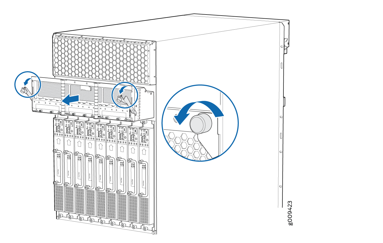
Before you remove a PDM, be aware of the following:

Note:

The minimum number of PDMs must be present in the router at all times.

Warning:

Before performing DC power procedures, disconnect all power sources. To ensure that all power is off, locate the circuit breaker on the panel board that services the DC circuit, switch the circuit breaker to the OFF position, and tape the switch handle of the circuit breaker in the OFF position.

CAUTION:

To maintain proper cooling and prevent thermal shutdown of the operating power supply unit, each PDM slot must contain either a PDM or a blank panel. If you remove a PDM, you must install a replacement PDM or a blank panel shortly after the removal.

Note:

After powering off a PDM, wait at least 60 seconds before turning the circuit breaker back on.

  1. Switch off the dedicated customer site circuit breaker for the PDM being removed. Follow your site's procedures for ESD.
  2. Make sure that the voltage across the DC power source cable leads is 0 V and that there is no chance that the cables might become active during the removal process.
  3. Verify that the –48V LEDs on the PDM to be removed are not lit.
  4. Attach an electrostatic discharge (ESD) grounding strap to your bare wrist, and connect the strap to one of the ESD points on the chassis.
  5. Move the DC circuit breaker on the power input source to the OFF position.
  6. Remove the clear plastic covers protecting the terminal studs on the faceplate.
  7. Remove the nut and washers from each of the terminal studs. (Use a 7/16-in. [11 mm] nut driver or socket wrench.)
  8. Remove the cable lugs from the terminal studs.
  9. Carefully move the power cables out of the way.
  10. Loosen the two captive screws on the locking levers, and pull away from the chassis.
    Note:

    For the MX2020 Router, pull down the PDM3/Input1 and PDM1/Input1 locking levers to release the PDM from the chassis, and pull up the PDM0/Input0 and PDM2/Input0 locking levers to release the PDM from the chassis.

    Note:

    For the MX2010 and MX2008 Routers, pull down the PDM1/Input1 locking levers to release the PDM from the chassis, and pull up the PDM0/Input0 locking levers to release the PDM from the chassis.

  11. The PDM is extended slightly away from the chassis. See Figure 1 (MX2020), Figure 2 (MX2010), and Figure 3 (MX2008)
    Figure 1: Removing a DC PDM from an MX2020 RouterRemoving a DC PDM from an MX2020 Router
    Figure 2: Removing a DC PDM from an MX2010 RouterRemoving a DC PDM from an MX2010 Router
    Figure 3: Removing a DC PDM from an MX2008 RouterRemoving a DC PDM from an MX2008 Router
  12. With both hands, grasp the two handles and gently pull the PDM straight out of the chassis.
    CAUTION:

    Do not touch the power connectors on the back of the PDM. It can get damaged.

    Note:

    Each PDM slot not occupied by a DC PDM must be covered by a PDM blank panel.

  13. Place the PDM onto an antistatic mat or into a ESD bag.

Installing an MX2000 Router DC Power Distribution Module (-48 V)

Warning:

Before performing DC power procedures, disconnect all power sources. To ensure that all power is off, locate the circuit breaker on the panel board that services the DC circuit, switch the circuit breaker to the off position, and tape the switch handle of the circuit breaker in the off position.

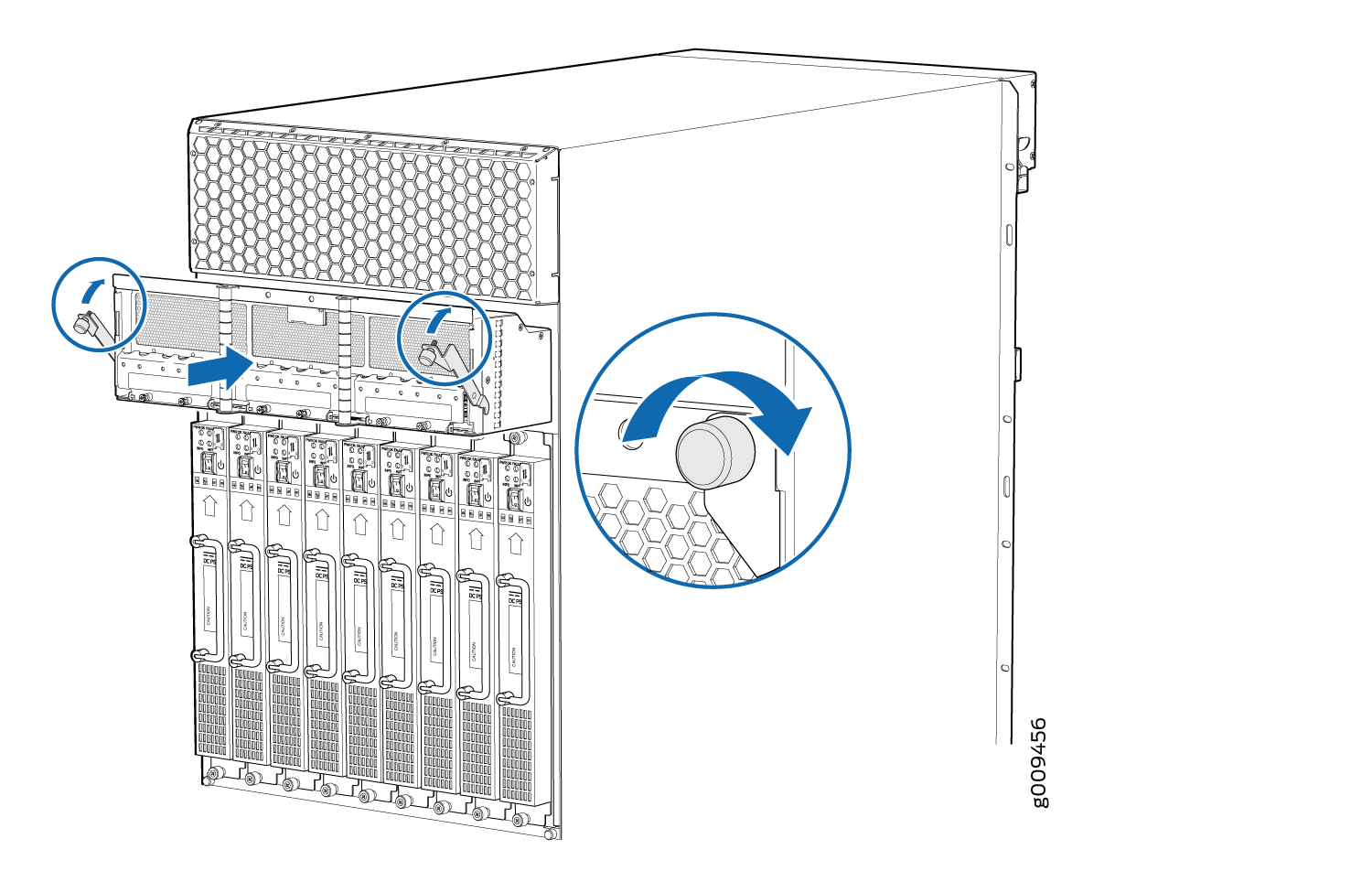
To install a DC power distribution module (PDM) in an MX2000 Router:

  1. Ensure that the voltage across the DC power source cable leads is 0 V and that there is no chance that the cable leads might become active during installation.
  2. Attach an electrostatic discharge (ESD) grounding strap to your bare wrist, and connect the strap to one of the ESD points on the chassis.
  3. Move the DC circuit breaker on the power input source to the off position.
  4. [Optional]—If you are switching from an AC PDM to DC PDM, see Converting an MX2000 Router Between AC and DC Power for instructions on how to change the setting on the internal bar of the power distribution unit (PDU) cage to DC.
  5. Remove the blank panel covering the PDM slot in the chassis.
  6. Open the locking levers on the PDM.
  7. While holding both handles, guide the PDM until the locking levers are inserted into the chassis. With both hands push the locking levers simultaneously until the PDM is fully seated into the chassis (see Figure 4(MX2020), Figure 5(MX2010), or Figure 6 (MX2008).
    Figure 4: Installing an MX2020 Router DC Power Distribution ModuleInstalling an MX2020 Router DC Power Distribution Module
    Figure 5: Installing an MX2010 Router DC Power Distribution ModuleInstalling an MX2010 Router DC Power Distribution Module
    Figure 6: Installing an MX2008 Router Power Distribution ModuleInstalling an MX2008 Router Power Distribution Module
  8. Tighten both captive screws on the PDM. Apply between 10 lb-in. (1.13 Nm) to 12 lb-in. (1.35 Nm) of torque to each screw. Do not overtighten the screws.
  9. Remove the clear plastic cover protecting the terminal studs on the PDM faceplate.
  10. Remove the nut and washers from each of the terminal studs.