Connecting an MX2000 DC Router Power Distribution Module (-48 V) Cable
Before performing DC power procedures, disconnect all power sources. To ensure that all power is OFF, locate the circuit breaker on the panel board that services the DC circuit, switch the circuit breaker to the OFF position, and tape the switch handle of the circuit breaker in the OFF position.
Ensure that you have connected the chassis to earth ground. See Grounding an MX2000 Router.
To connect a power cable for a DC PDM:
- Secure the power cable lug to the terminal studs, first
with the flat washer, then the split washer, and finally with the
nut. Apply between 23 lb-in. (2.6 Nm) and 25 lb-in.
(2.8 Nm) of torque to each nut (see Figure 1). Do not overtighten
the nut. (Use a 7/16-in. [11 mm)] torque-controlled driver
or socket wrench.)Note:
The input positions for the RTN (return) DC terminal studs and the -48V (input) DC terminal studs correspond to the DC Power Supply Module (PSM) directly above and below. The DC PSM slot positions are labeled, but the DC PDM cable positions that correlate to the PSM positions are not labeled.
Attach the positive (+) DC source power cable lug to the RTN (return) terminal.
Attach the negative (–) DC source power cable lug to the –48V (input) terminal.
Figure 1: Connecting Power Cables to the DC Power Distribution Module (-48 V)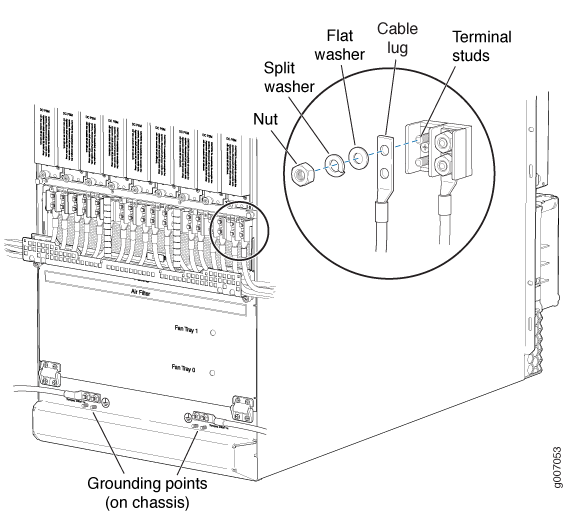
CAUTION:Ensure that each power cable lug seats flush against the surface of the terminal block as you are tightening the nuts. Ensure that each nut is properly threaded onto the terminal stud. The nut should be able to spin freely with your fingers when it is first placed onto the terminal stud. Applying installation torque to the nut when the nut is improperly threaded may result in damage to the terminal stud.
CAUTION:The maximum torque rating of the terminal studs on the DC PDM is 25 lb-in. (33.89 Nm). The terminal studs may be damaged if excessive torque is applied. Use only a torque-controlled driver or socket wrench to tighten nuts on the DC PDM terminal studs.
CAUTION:You must ensure that power connections maintain the proper polarity. The power source cables might be labeled (+) and (-) to indicate their polarity. There is no standard color coding for DC power cables. The color coding used by the external DC power source at your site determines the color coding for the leads on the power cables that attach to the terminal studs on each power supply.
Note:The DC PDMs in slots PDM0/Input0, PDM2/Input0, (and PDM1/Input1, and PDM3/Input1 on MX2020 Routers) can be powered by dedicated power feeds derived from feed A, or feed B. This configuration provides the commonly deployed A/B feed redundancy for the system to balance the power draw. For information about connecting to DC power sources, see MX2000 Router DC (-48 V) Power Subsystem Electrical Specifications.
Note:Make sure the amperage switch is set to 60 A or 80 A to match the DC circuit input feed.