FRR Auto Design
When the FRR Design parameters are submitted for Auto Design, the program will automatically create backup tunnels as follows:
If the Protection Type is set to Link, then FRR Auto Design will automatically design the FRR-LP backup tunnels necessary to protect (1) Links along the paths of LSP tunnels requesting FRR protection, and (2) Individual links that have been marked to request FRR protection.
If the Protection Type is set to Node, then FRR Auto Design will automatically design the FRR-NP backup tunnels necessary to protect (1) Nodes along the paths of LSP tunnels requesting FRR protection (excluding the source and destination nodes) and (2) The destination node of links that have been marked to request FRR protection.
Note:When selecting either Node Protection or Link Protection, the Auto Design will automatically enable FRR for all the links along the paths of LSP tunnels requesting FRR protection. If this is not desired, users should use tuning instead of auto design, or in the case of Juniper, select “Auto Bypass” as described below.
If the Design Bandwidth Reference Bandwidth Source is set to Sub-Pool (for Cisco only) then only the links that(1) require FRR protection and (2) have subpool bandwidth allocated will be considered for protection in FRR Auto Design.
If the Protection Type is set to Auto Bypass (for Juniper bypass creation), then FRR Auto Design will automatically design the bypass tunnels for Juniper for FRR-enabled links along the paths of FRR-enabled LSP tunnels. After selecting this option, you will be prompted with the option to design paths using (a) the RSVP signaling bandwidth as the Design Bandwidth or (b) the Backup bandwidth as the Design Bandwidth. Select option (a) if you wish to simulate Juniper’s auto bypass generation. Select option (b) to help ensure there is enough bandwidth on the backup tunnel to protect the primary tunnels.
Note:The Auto Bypass Protection type will preserve the link’s FRR settings and avoid creating backup tunnels for links not enabled for FRR.
Please read through the explanations of the Design options in the previous section carefully for a complete description of each of the FRR Design options. Though the design options may initially appear complex, understanding the function of each option will provide you with enormous flexibility. Once you have specified the desired properties in the FRR Design window, click the “AUTO Design” button.
If you already have some existing fast reroute tunnels in the network, you may also see the following confirmation windows: “Routes and bandwidth for all FRR link protection backup tunnels will be adjusted. Continue?” or “Remove configured paths for 10 FRR link backup tunnels?”
In the Console window, the number of placed/unplaced/deactivated paths for the new tunnels will be displayed. You should see something similar to this:
Diversity Level= SITE
Tunnel       Site+Link-Diversity      Link-Diversity     No-Diversity    Notplaced   Deactivated
FRRBackup      10                                0                     0                       0            0
FRR Design Report
When the design is completed, you will be asked whether you wish to view the FRR design report. The report is saved as FRRDSGNRPT.runcode in your File Manager Output Path. To view this report at a later time, right-click on the report in the File Manager and choose Open in Report Viewer from the popup menu.
To see the FRRDSGNRPT report listed in the File Manager, you may need to refresh the File Manager contents first, either by pressing the “Refresh” button or alternatively, the <F5> key.

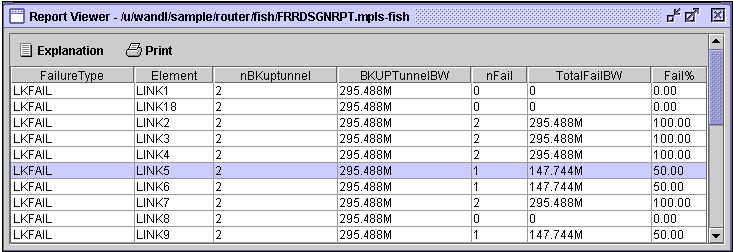
After the Auto Design has been performed and FRR backup tunnels created, the FRR Design Report displays the result of failing each FRR-protected link or node. For example, in Figure 360, the highlighted table entry indicates that when LINK5 is failed, there are two FRR-LP backup tunnels protecting the link. The total bandwidth of these two backup tunnels is 295.488Mbps. Of these two, one failed to be placed during the link failure. The total bandwidth of this failed backup tunnel is 147.744Mbps, accounting for 50% of the total backup tunnel bandwidth.
FRR Design Report Fields
FailureType: Possible values are LKFAIL, NODEFAIL, and FACFAIL, indicating link, node or facility failure.
If the Link Diversity Level was specified for the Auto Design, then the program will take down each node/link individually and try to find a route that is both site-diverse and link-diverse. If there is none, it will try to find a link-diverse route.
If the Site Diversity Level was specified for the Auto Design, then the program will take down each node/link individually and try to find a site-diverse route. If there is none, it will try to find a link-diverse route. The rationale is that even if site diversity is not met, a link-diverse route is better than no route at all.
If the Facility Diversity Level was specified for the Auto Design, then the program will take down each node/link individually and try to find a route that is both facility-diverse and site-diverse. If there is none, it will try to find a link-diverse route.
Element: Indicates the failed element. If Node Protection Type (or Link Protection Type) was specified for the Auto Design, then all nodes (or all the links) in the network will be failed and brought back up one at a time.
nBKuptunnel: Indicates the number of FRR backup tunnels that are routed through the network Element.
BKUPTunnelBW: Indicates the total backup bandwidth of all the FRR backup tunnels protecting the failed element.
nFail: Indicates the number of backup tunnels that failed to be placed during the element failure.
TotalFailBW: Indicates the total bandwidth of the backup tunnels that failed to be placed during the element failure.
Fail%: Indicates the percentage of backup tunnel bandwidth that failed to be placed during the element failure.
View Created FRR Backup Tunnels
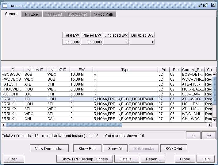
To view the newly designed FRR backup tunnels, select Network > Elements > Tunnels to display all LSP tunnels in the network. Notice that the Type field will indicate whether the FRR backup tunnels are for Link Protection (“FRRLK”) or Node Protection (“FRRND”) and that the No Autoroute Announce flag (“NOAA”) is automatically turned on.
Other possible type fields (for Cisco) are “BKSP” or “BKGP”, indicating that the backup tunnel carries Sub-Pool or Global-Pool tunnels, respectively; this corresponds to the user’s settings of the Protected Tunnel Type field in the FRR Design parameters.

You can further examine the FRR backup tunnels created from the View/Tune Paths window as described in Viewing Primary Tunnels Protected by a Bypass Tunnel.
