Help us improve your experience.

Let us know what you think.

Do you have time for a two-minute survey?


L3 Hub-and-Spoke VPN

Merging Hub and Spokes

For the existing hub-and-spoke VPNs, NorthStar Planner does not automatically group together the vrf associated with the hub and the vrf associated with the spoke. This should not affect routing, but for readability purposes, users can manually group together the hub and spoke into one VPN using the following procedures.

  1. If you are in the Online mode, click the Offline button to switch into the Offline mode.
  2. Next, select the Modify mode button to switch into Modify mode.
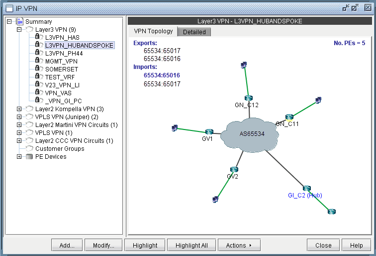
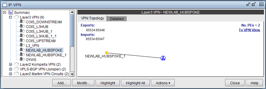
  3. Select Modify > Services > VPN, and identify the vrf’s to combine. If you select the To Import/Export Relation View from the VPN Topology tab, it will show you which other instances to combine together.
    Figure 1: Spoke ViewSpoke View
    Figure 2: Import/Export Relation View (Spoke -> Hub)Import/Export Relation View (Spoke -> Hub)

    Since some hub-and-spoke VPN’s can have an upstream and downstream spoke, it may be best to check the Import/Export Relation View of the hub.

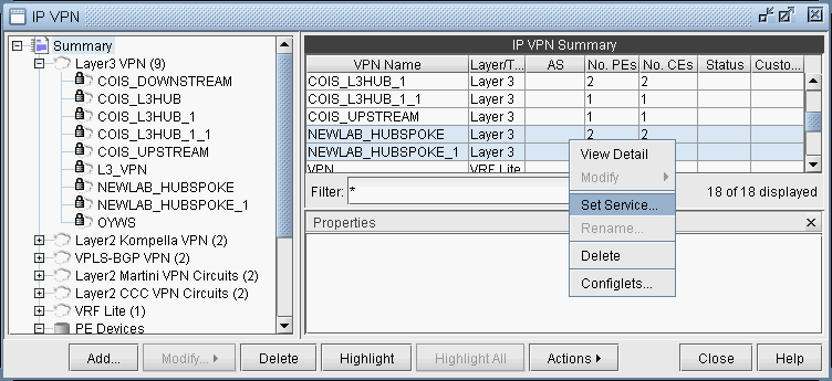
  4. Select the hub-and-spoke components from the Summary > Layer 3 VPN list on the right pane and use the Actions > Set Service menu to provide a name for the hub-and-spoke VPN.
    Figure 3: Specifying the Hub and Spoke VPN via “Set Service”Specifying the Hub and Spoke VPN via “Set Service”
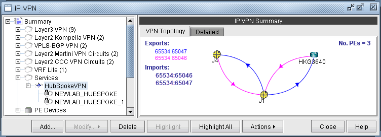
  5. Select the newly defined service from the Services category to view the VPN topology of the hub and spoke VPN.
    Figure 4: Hub and Spoke VPN TopologyHub and Spoke VPN Topology
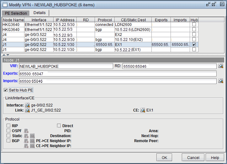
  6. For the combined VPN, select the Modify > Protocol. To identify the Hub PE node, right-click the table column header and select Table Options, and add the property “Hub” to the “Selected Items” list on the right-hand side, to see the Hub checkbox column.
    Figure 5: Hub Checkbox ColumnHub Checkbox Column
  7. By looking at the Exports and Imports, you can identify 2 sets of nodes with opposite imports and exports. One set of nodes should be specified as the Hub PE. For the Node which is a Hub PE, select the row corresponding to the outgoing interface, and then select the “Set to Hub PE” checkbox. Click OK when you are done.
  8. To update the network, select Modify > Update Network State. Then reopen the VPN window from Modify > Services > VPN.
  9. If you are working on the live network (online module), you will want to preserve this setting for future use, so that it does not have to be repeated. To do this, first create the directory /u/wandl/data/.network_plan from the File Manager, if it does not exist.
  10. Click the Design mode button to switch back to Design mode.
  11. Save the network to /u/wandl/data/.network_plan via the File > Save Network... menu using the default runcode x.
  12. Now that the network is saved into the .network_plan directory, switch back to Online mode.
  13. From Admin > Task Manager, New Task, rerun a Scheduling Live Network Collection task. Be sure to select the checkbox option to consolidate with existing data. At this point, it is only necessary to process the network configuration files and not to recollect the entire network, so for the “Data to Be Collected or Processed”, you can “Deselect All” and select only the “Process” checkbox for the Configuration type. Select Next and then Finish.
  14. Once the task is complete, open Network > Services > VPN and check to ensure that the changes have been preserved.

Adding a New Layer 3 Hub-and-Spoke VPN

Configuring a L3 Hub-and-Spoke VPN is similar to configuring a regular L3 full-meshed VPN, except for the following additional steps.

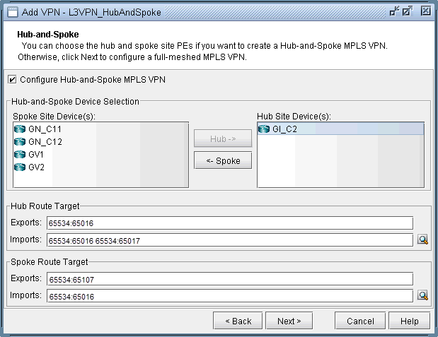
  1. First follow the steps outlined in previous section on L3 VPN configuration until you reach the Hub-and-Spoke configuration window. Click on the checkbox that says Configure Hub-and-Spoke MPLS VPN, and then move each PE to the appropriate list (Spoke Site Device(s) list or Hub Site Device(s) list) by using the Hub-> and <-Spoke buttons. The VPN Wizard automatically suggests RT exports and imports for both the hub sites and the spoke sites in order to establish a hub-and-spoke relationship. As before, you have the option to change the RT list by editing the suggested export or import values or by using RTs from the Route Targets table (by clicking on the magnifying glass icon).

    Figure 6: Hub-and-spoke VPN configurationHub-and-spoke VPN configuration
  2. Click on Next to get to the window where you would configure PE facing CE interfaces as described in the previous section on L3 VPN configuration. The following figure shows what the configuration looks like after the interfaces have been assigned. Notice that GI_C2 is configured as the hub site.

    Figure 7: Assigning PE facing CE interfaces in the Hub-and-Spoke VPNAssigning PE facing CE interfaces in the Hub-and-Spoke VPN
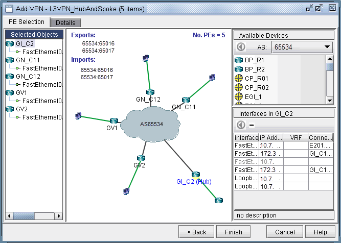
  3. After configuring the PE-CE protocol details under the Details tab (as described in the previous section on L3 VPN configuration), the resultant L3 hub-and-spoke VPN is shown in the following figure. Notice that Import RT 17301:65016 is highlighted to indicate that it is only an import RT for the HuB site(s).

    Figure 8: Newly created Hub and Spoke VPNNewly created Hub and Spoke VPN