Creating Routing Instances
If you have configuration files for your network, you can import the configuration files to create a network model using the File>Import Data menu as described in Router Data Extraction Overview. The interfaces will automatically be associated with the routing-instance or process IDs that they belong to.
For Juniper routers, the interfaces listed under the [edit routing-instances routing-instance-name] block will be assigned that routing-instance-name. Similarly, for Cisco routers, the interfaces whose addresses are advertised under the network statements of the “router ospf <processID>” block will be assigned that processID.
Note that if an interface is not enabled for OSPF, it will be assigned to a reserved category called “NOPROT” when the network is loaded. Similarly, if the interface is enabled for OSPF but has no process ID, it will be assigned to a reserved category called “NOID” when the network is loaded.
To view the associations of routing instances to interfaces, select Network > Elements > Interfaces... When selecting an interface, the bottom pane’s Advanced tab will show the process ID/routing instance in the OSPF PID field. To view the routing instance as a column of the table, right-click on the header row and select Table Options... Then add OSPF PID from the Available Item(s) list to the Selected Item(s) list.
OSPF process IDs (PID) or routing instance names can also be associated with interfaces via the Modify Interface window’s Advanced tab for what-if testing, as shown in Figure 1. To access this window, click the Modify action mode button to switch to Modify mode and then select Modify > Elements > Interfaces. Then select the interfaces you want to modify and click Modify. An OSPF process on a Cisco router is an integer number, while an OSPF process on a Juniper router is usually a name.
Figure 1: Modify Interface Window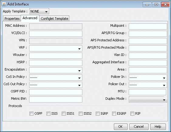
By default, multiprocess checking is turned off. To turn on multiprocess checking for routing instance analyses, select the Tools > Options > Design, Path Placement options pane and set Ignore Multiprocess in the lower right corner to “False”. Alternatively, you can add the parameter ignoremultiprocess=0 to the project’s dparam.runcode file. To turn on multiprocess checking by default for all new network projects, create or edit the file /u/wandl/db/misc/dparam.txt and add the line “ignoremultiprocess=0”.
To visualize Routing Instances/OSPF PIDs on the map by associating them together with a color, you can specify a routeinstance file in the specification file as indicated in File Format on page 214 by adding the entry “routeinst= filename” to the specification file while the network is closed, substituting filename with the name of the route instance definition file . This file can also be indicated during a Configuration file Import (File>Import) by specifying the RouteInstance file on the Misc tab of the Import Network Wizard. Alternatively, you can make the association for the current network session by selecting Modify > Protocols > OSPF/ISIS Routing Instance from the main menu while in Modify mode.
Figure 2: Routing Instance Window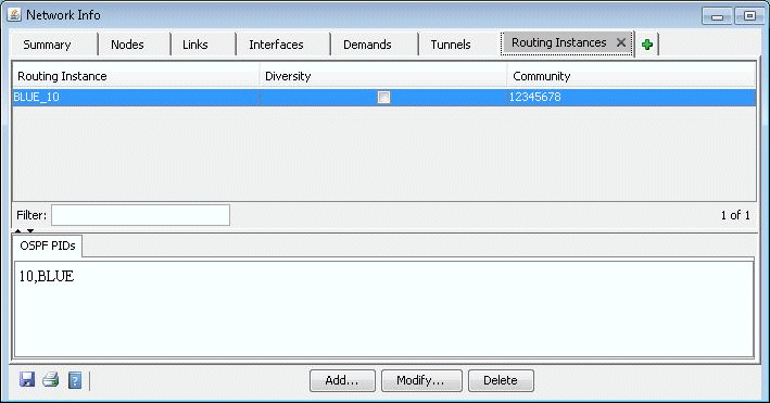
Click the Add button, and a new window will appear as shown in Figure 3.
Figure 3: Add Routing Instance Window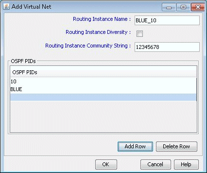
Enter in the routing instance name. Then click Add Row for each OSPF process ID (for Cisco) or routing-instance-name (for Juniper) that should be mapped to this routing instance.
Field
Description
Routing Instance Name
The name used to identify the partitioned network.
Routing Instance Diversity
Not currently used
Routing Instance Community String
Community Strings are used for BGP next-hop checking to make sure that the BGP next hop is in the desired routing instance
OSPF PIDs
The OSPF process IDs and names belonging to this routing instance. The same OSPF PID cannot be used in more than one Routing Instance.
Once the routing instance has been defined through the route instance file or through the Modify > Protocols > OSPF/ISIS Routing Instance menu, links can also be associated with a Routing Instance via the Modify Link window (accessed through Modify > Elements > Links), as shown in Figure 4. However, this setting will be overridden if the interfaces attached to the links are also associated with a Routing Instance in the Modify > Elements > Interfaces window. Interfaces on both ends of a link should belong to the same Routing Instance.
Figure 4: Modify Link Window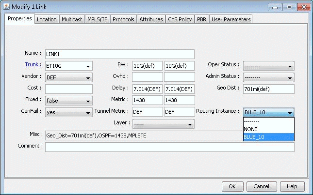
If you select Subviews > Routing Instances in the Topology Map, the links will be displayed using the color specified for the corresponding routing instance.
Figure 5: Topology Map - Routing Instance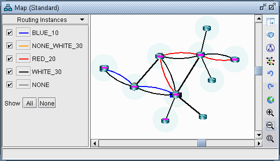
You can toggle the checkmark next to a routing instance to turn on or off the display of links whose interfaces are defined to be in that routing instance. Additionally, you can modify the color associated with a routing instance on the map by clicking the color box next to the routing instance name.
