QFX5700 Power System
The QFX5700 switch is powered by 3000 W redundant hot-removable and hot-insertable pre-installed AC/HDVC or DC power supplies. QFX5700-BASE Configuration (One RCB and one FEB) requires 1 + 1 PSU redundancy. If you choose the QFX5700-BASE Configuration, this can be connected to the same source or two separate sources for 1+1 redundancy. If any power supply unit fails, you can replace it without powering off or disrupting the routing function, the other power supply units will balance the electrical load without interruption. Each power supply unit has two outputs: 12 V and 12 V standby. Two counter-rotating fans in each power supply unit provide front to back cooling. The input voltages are as follows:
-
AC input voltage range: 200 - 277 VAC
-
DC input voltage range: 40 VDC Min, 72 VDC maximum
Do not mix AC and DC power supplies in the same chassis.
QFX5700 AC/HVDC Power Supply Description
The input power to the AC/HVDC power supplies can be AC power or HVDC power. The power supplies automatically detect whether there is AC or HVDC input voltage and manage the power accordingly. AC power can be 180–305 VAC input voltage and HVDC power can be 190–400 VDC input voltage. Each 3000- W AC/HVDC power supply unit has a single AC or HVDC input and provides 12 V power to the system.
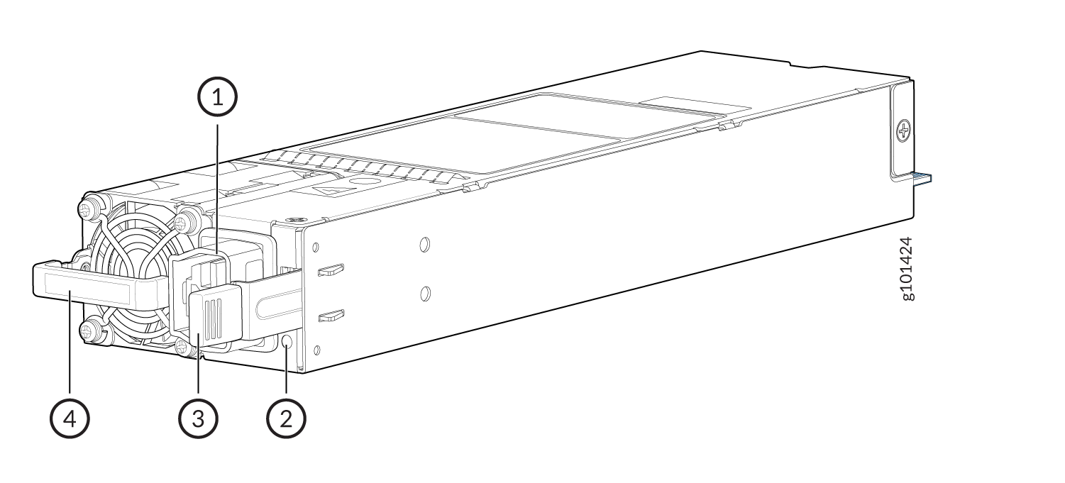
1 — Power plug connector | 3 — Ejector level |
2 — Status LED | 4 — Orange handle |
The QFX5700 operates within the AC/HVDC input voltage range listed in the table below.
|
Parameter |
Minimum |
Rated |
Maximum |
|
Input voltage (AC) |
180 VAC |
200–277 VAC |
305 VAC |
|
Input voltage (HVDC) |
190 VAC |
240–380 VDC |
400 VDC |
|
AC input line frequency |
47 Hz |
50–60 Hz |
63 Hz |
| Parameters | 8x QFX5KFPC‑ 20Y 144x50G | 8x QFX5KFPC‑16C 128x100G | 8x QFX5KFPC‑ 4CD 32x400G |
|---|---|---|---|
| Typical power consumption | 751 W | 1259 W | 1095 W |
| Maximum power consumption | 1622 W | 2271 W | 1762 W |
Typical power consumption is measured at 25°C ambient temperature, and at 50% load with IMIX traffic, without MACsec and excluding transceivers. Maximum power consumption is measured at 40°C ambient temperature with SR optics, and at 100% load with IMIX traffic, with MACsec on QFX5K‑FPC‑20Y and QFX5K‑FPC‑16C, without MACsec on QFX5K‑FPC‑4CD. Power consumption is subject to operating conditions and unit‑to‑unit variations; the power consumption measurements were taken at 200‑277 VAC PSUs.
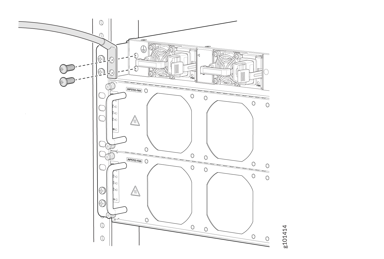
Figure 2 shows the location of the AC power supplies on the QFX5700 FRU panel.
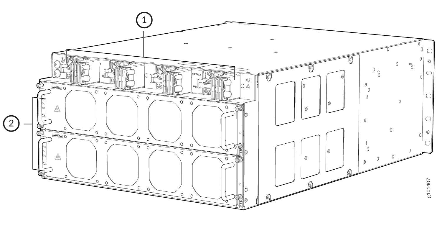
1 — PSUs | 2 — Fan trays |
QFX5700 AC/HVDC Power Supply LEDs
Each QFX5700 AC power supply has a status LED on the power supply faceplate. QFX5700 switch AC/HVDC power supply unit uses an amber and green bi–color LED to indicate the operating state.
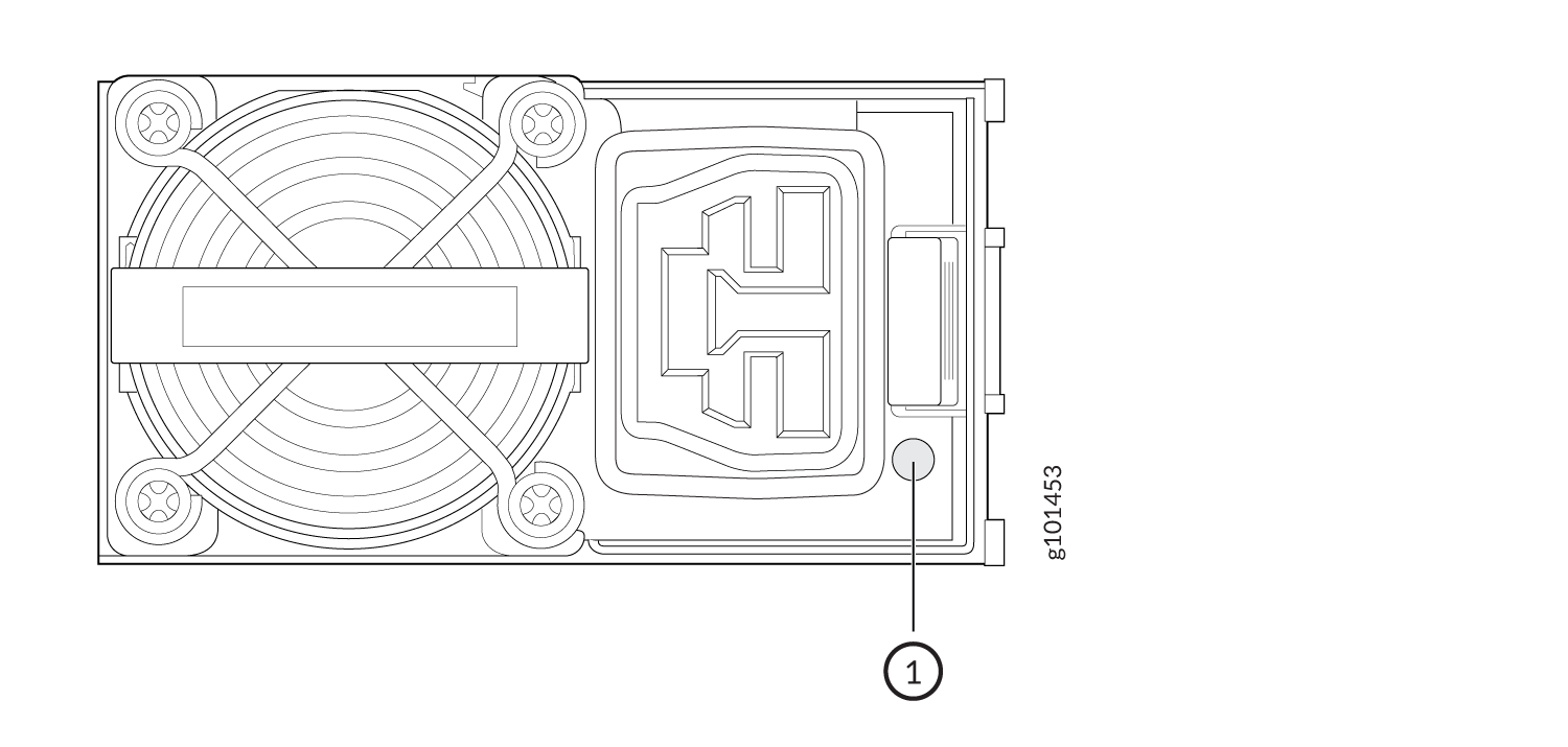
1 — Power Supply LED |
|
State |
Green |
Amber |
|---|---|---|
|
The PSU is on and operating properly |
On |
Off |
|
Power supply does not have AC power |
Off |
Off |
|
The power supply unit shut down due to a critical event. Possible causes: high temperature, high power, high current, fan failure |
Off |
On |
|
The power supply unit is operating but there are warning events. Possible conditions: high temp (inlet temperature is greater than 53 degrees or a hot spot temperature is greater than 95 degrees), high power, high current, slow fan (less than 1200 rpm) |
Off |
Blinking amber |
|
PSU output disabled by system software or other PSU in chassis on with 12VSB. |
Blinking |
Off |
You can get additional information about the status of the power supply units using
the show chassis powercommand and the show chassis power
detailcommand.
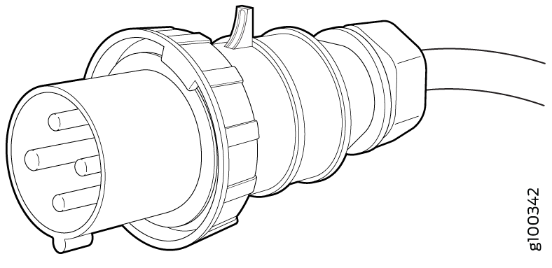
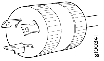
QFX5700 AC Power Cord Specifications
Detachable AC power cords are shipped with the chassis if you include them as part of your order. The plug end of the power cord fits into the power source outlet that is standard for your geographical location.
In North America, AC power cords must not exceed 14.75 feet (approximately 4.5 meters) in length, to comply with National Electrical Code (NEC) Sections 400-8 (NFPA 75, 5-2.2) and 210-52 and Canadian Electrical Code (CEC) Section 4-010(3). The cords that can be ordered for the QFX5700 are in compliance.
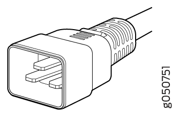
Table 4 lists AC power cord specifications provided for each country or region.
|
Locale |
Cord Set Rating |
Plug Standards |
Spare Juniper Model Number |
Graphic |
|---|---|---|---|---|
|
Argentina |
250 VAC, 16 A, |
IRAM 2073 Type RA/3 |
CBL-JNP-SG4-AR |
|
|
Australia and New Zealand |
250 VAC, 15 A |
AS/NZS 4417 |
CBL-JNP-SG4-AU |
|
|
Brazil |
250 VAC, 20 A |
NBR 14136 Type BR/3 |
CBL-JNP-SG4-BR |
|
|
China |
250 VAC, 16 A |
GB2099 |
CBL-JNP-SG4-CH |
|
|
Europe |
250 VAC, 16 A |
CEE 7/7 STRAIGHT |
CBL-JNP-SG4-EU |
|
|
India/South Africa |
250 VAC, 16 A |
SANS 164/1 |
CBL-JNP-SG4-SA |
|
|
Israel |
250 VAC, 16 A |
SI 32/1971 Type IL/3G |
CBL-JNP-SG4-IL |
|
|
Italy |
250 VAC, 16 A |
CEI 23-16 |
CBL-JNP-SG4-IT |
|
|
US only |
250 VAC, 20 A |
C20 to Anderson 3-5958p4 |
CBL-JNP-SG4-C20 |
|
|
North America |
250 VAC, 16 A |
Locking NEMA L6-20P |
CBL-JNP-SG4-US-L |
|
|
250 VAC, 16 A |
NEMA 6-20P |
CBL-JNP-SG4-US |
|
|
|
250 VAC, 16 A |
NEMA I7-20P |
CBL-JNP-SG4-HVAC |
|
|
|
China, Europe, and Japan |
250 VAC, 16 A |
C20 to Anderson 3-5958p4 |
CBL-JNP-SG4-C20-CH |
|
|
Switzerland |
250 VAC, 16 A |
CEI 23-50 |
CBL-JNP-SG4-SZ |
|
You must provide 16 A, 250 V circuit breaker or as required by local code to the 16 A power cord connected to AC mains of each power supply.
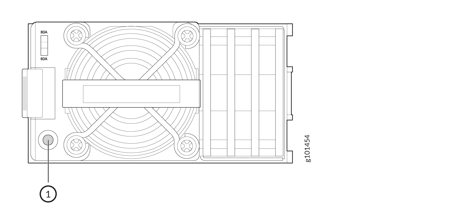
QFX5700 DC Power Supply Description
The QFX5700 DC power supplies are hot-removable and hot-insertable FRUs. Each 3000 W power supply unit has a single DC input and provides 12 VDC output with a standby voltage of 12 VDC. The QFX5700 DC power supplies can operate with an input current of 80 A or 60 A.
Do not mix AC/HVDC and DC power supplies in the same chassis.
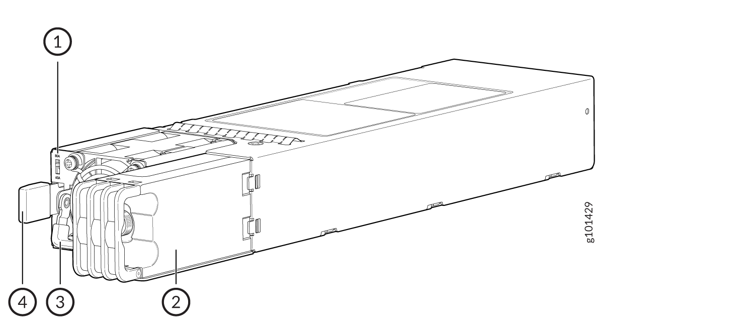
1 — DC input current selector (DIP switch) | 3 — Handle |
2 — Inlet terminal block | 4 — Ejector Lever |
- QFX5700 DC Power Supply LED
- QFX5700 DC Input Current Selector
- QFX5700 Input DC Voltage Specification
- 60 A Input Feed Power Management
- QFX5700 DC Power Cables
- QFX5700 DC Power Lugs
- QFX5700 DC Power Cables
QFX5700 DC Power Supply LED
Each QFX5700 DC power supply unit has a status LED on the power supply unit faceplate.
1 — Power supply status LED |
|
LED Color |
Power Supply State |
|
Solid green |
The power supply unit is on and in the OK state. |
|
Off |
The power supplies do not have DC power. |
|
Blinking green |
PSU output disabled by system software or other PSU in chassis ON with 12VSB. |
|
Solid amber |
The DC power cord is unplugged but the second power supply unit still has DC power. |
|
Blinking amber |
The power supply unit is operating but there are warning events. Possible causes: high temp, high power, high current, slow fan. |
The 60 A DC power supply unit capacity changes when the input voltage is below or above the under voltage limit as follows:
-
When the 60 A DC power supply unit input voltage is above the input under voltage warning limit, its capacity is 2700 W.
-
When the input voltage is below the input under voltage warning limit, the power supply unit capacity is reduced to 2200 W.
When the input voltage is above the input under voltage warning limit, the software adjusts the system capacity and reallocates power to the FRUs based on the new system capacity.
You can get additional information about the status of the PSMs using the show chassis power command and show chassis power detail command.
QFX5700 DC Input Current Selector
The QFX5700 DC PSM can operate with an input current of 80 A or 60 A. You select the input rating by moving the DC input current selector (DIP switch) to the desired setting. If you select 60 A, the PSM limits the output power so that the input current does not exceed 60 A under normal steady-state operation. If you select 80 A, the PSM limits the output power so that the input current does not exceed 80 A.
For example:
|
If you select... |
Then... |
|---|---|
|
60 A |
The PSM limits the output power to 2200 W when the input voltage is between 40V and 48V. It linearly increases the output power if the input voltage increases. The PSM provides 2700 W output power when the input voltage is between 48V and 72V. |
|
80 A |
The PSM provides 3000 W output power throughout the input voltage range from 40 VDC to 72 VDC. |
QFX5700 Input DC Voltage Specification
The QFX5700 DC PSMs operate within the DC input voltage range listed in .
Depending on the available input source, Juniper recommends that the 48-VDC facility DC source be equipped with a 2 pole circuit breaker rated at a minimum of 60 A (48 VDC) or 80 A (48 VDC) based on DIP switch current setting, or as required by local code.
|
Input Switch Setting |
Minimum Input DC Voltage |
Rated Input DC Voltage |
Maximum Input DC Voltage |
Maximum Input DC Current |
Maximum Output Power |
|---|---|---|---|---|---|
|
60 A |
40 VDC |
48 VDC to 60 VDC |
72 VDC |
60 ADC |
2700 W |
|
80 A |
40 VDC |
48 VDC to 60 VDC |
72 VDC |
90 ADC |
3000 W |
60 A Input Feed Power Management
The 60 A DC PSM capacity changes when the input voltage is below or above the under-voltage limit, as follows:
-
When the 60 A DC PSM input voltage is above the input under-voltage warning limit, its capacity is 2700 W.
-
When the input voltage is below the input under-voltage warning limit, the PSM capacity is reduced to 2200 W.
When the input voltage is above the input under-voltage warning limit, the software adjusts the system capacity and reallocates power to the FRUs based on the new system capacity.
QFX5700 DC Power Cables
You must supply DC power cables that meet the specifications required by the local code, laws, and standards. The wire insulation is color coded. Green is ground, black is line, and white is neutral. The wires are labeled (+) and (–) to indicate their polarity.
You must ensure that power connections maintain the proper polarity.
For field-wiring connections, use copper conductors only.
Make sure that DC power cables do not block access to QFX5700 components or lie on the ground where people can trip on them.
QFX5700 DC Power Lugs
The accessory box shipped with the QFX5700 includes the cable lugs that attach to the terminal studs of each power supply module. (The cable lug shown in Figure 36 on page 61 is also used for grounding the chassis). The cable lugs are dual hole and sized to fit M6 at 15.86-mm (0.625-in.) center line. For grounding, the lug that should be used can be LCC4-14AH-Q as per local code.
QFX5700 DC Power Cables
You must supply the DC power cables that meet the specifications required by the local code, laws, and standards. The insulation color of the wires are color coded. Green is ground, black is line, and white is neutral. The wires are labeled (+) and (–) to indicate their polarity.
You must ensure that power connections maintain the proper polarity.
For field-wiring connections, use copper conductors only.
DC Power cables must not block access to QFX5700 components or drape where people could trip on them.