Cable and Connector Specifications for QFX Series Devices
The transceivers that are supported on QFX5700 devices use fiber-optic cables and connectors. The type of connector and the type of fiber depends on the transceiver type.
You can determine the type of cable and connector required for your specific transceiver by using the Hardware Compatibility Tool.
To maintain agency approvals, use only a properly constructed, shielded cable.
The terms multifiber push-on (MPO) and multifiber termination push-on (MTP) describe the same connector type. The rest of this topic uses MPO to mean MPO or MTP.
12-Fiber MPO Connectors
There are two types of cables used with 12-fiber MPO connectors on Juniper Networks devices—patch cables with MPO connectors on both ends, and breakout cables with an MPO connector on one end and four LC duplex connectors on the opposite end. Depending on the application, the cables might use single-mode fiber (SMF) or multimode fiber (MMF). Juniper Networks sells cables that meet the supported transceiver requirements, but it is not required to purchase cables from Juniper Networks.
Ensure that you order cables with the correct polarity. Vendors refer to these crossover cables as key up to key up, latch up to latch up, Type B, or Method B. If you are using patch panels between two transceivers, ensure that the proper polarity is maintained through the cable plant.
Also, ensure that the fiber end in the connector is finished correctly. Physical contact (PC) refers to fiber that has been polished flat. Angled physical contact (APC) refers to fiber that has been polished at an angle. Ultra physical contact (UPC) refers to fiber that has been polished flat, to a finer finish. The required fiber end is listed with the connector type in the Hardware Compatibility Tool.
- 12-Fiber Ribbon Patch Cables with MPO Connectors
- 12-Fiber Ribbon Breakout Cables with MPO-to-LC Duplex Connectors
- 12-Ribbon Patch and Breakout Cables Available from Juniper Networks
12-Fiber Ribbon Patch Cables with MPO Connectors
You can use 12-fiber ribbon patch cables with socket MPO connectors to connect two transceivers of the same type—for example, 40GBASE-SR4-to-40GBASESR4 or 100GBASE-SR4-to-100GBASE-SR4. You can also connect 4x10GBASE-LR or 4x10GBASE-SR transceivers by using patch cables—for example, 4x10GBASE-LR-to-4x10GBASE-LR or 4x10GBASE-SR-to-4x10GBASE-SR—instead of breaking the signal out into four separate signals.
Table 1 describes the signals on each fiber. Table 2 shows the pin-to-pin connections for proper polarity.
Fiber |
Signal |
|---|---|
1 |
Tx0 (Transmit) |
2 |
Tx1 (Transmit) |
3 |
Tx2 (Transmit) |
4 |
Tx3 (Transmit) |
5 |
Unused |
6 |
Unused |
7 |
Unused |
8 |
Unused |
9 |
Rx3 (Receive) |
10 |
Rx2 (Receive) |
11 |
Rx1 (Receive) |
12 |
Rx0 (Receive) |
MPO Pin |
MPO Pin |
|---|---|
1 |
12 |
2 |
11 |
3 |
10 |
4 |
9 |
5 |
8 |
6 |
7 |
7 |
6 |
8 |
5 |
9 |
4 |
10 |
3 |
11 |
2 |
12 |
1 |
12-Fiber Ribbon Breakout Cables with MPO-to-LC Duplex Connectors
You can use 12-ribbon breakout cables with MPO-to-LC duplex connectors to connect a QSFP+ transceiver to four separate SFP+ transceivers—for example, 4x10GBASE-LR-to-10GBASE-LR or 4x10GBASE-SR-to-10GBASE-SR SFP+ transceivers. The breakout cable is constructed out of a 12-fiber ribbon fiber-optic cable. The ribbon cable splits from a single cable with a socket MPO connector on one end, into four cable pairs with four LC duplex connectors on the opposite end.
Table 3 describes the way the fibers are connected between the MPO and LC duplex connectors. The cable signals are the same as those described in Table 1.
MPO Connector Pin |
LC Duplex Connector Pin |
|---|---|
1 |
Tx on LC Duplex 1 |
2 |
Tx on LC Duplex 2 |
3 |
Tx on LC Duplex 3 |
4 |
Tx on LC Duplex 4 |
5 |
Unused |
6 |
Unused |
7 |
Unused |
8 |
Unused |
9 |
Rx on LC Duplex 4 |
10 |
Rx on LC Duplex 3 |
11 |
Rx on LC Duplex 2 |
12 |
Rx on LC Duplex 1 |
12-Ribbon Patch and Breakout Cables Available from Juniper Networks
Juniper Networks sells 12-ribbon patch and breakout cables with MPO connectors that meet the requirements described above. It is not required to purchase cables from Juniper Networks. Table 4 describes the available cables.
Cable Type |
Connector Type |
Fiber Type |
Cable Length |
Juniper Model Number |
|---|---|---|---|---|
12-ribbon patch |
socket MPO/PC to socket MPO/PC, key up to key up |
MMF (OM3) |
1 m |
MTP12-FF-M1M |
3 m |
MTP12-FF-M3M |
|||
5 m |
MTP12-FF-M5M |
|||
10 m |
MTP12-FF-M10M |
|||
socket MPO/APC to socket MPO/APC, key up to key up |
SMF |
1 m |
MTP12-FF-S1M |
|
3 m |
MTP12-FF-S3M |
|||
5 m |
MTP12-FF-S5M |
|||
10 m |
MTP12-FF-S10M |
|||
12-ribbon breakout |
socket MPO/PC, key up, to four LC/UPC duplex |
MMF (OM3) |
1 m |
MTP-4LC-M1M |
3 m |
MTP-4LC-M3M |
|||
5 m |
MTP-4LC-M5M |
|||
10 m |
MTP-4LC-M10M |
|||
socket MPO/APC, key up, to four LC/UPC duplex |
SMF |
1 m |
MTP-4LC-S1M |
|
3 m |
MTP-4LC-S3M |
|||
5 m |
MTP-4LC-S5M |
|||
10 m |
MTP-4LC-S10M |
24-Fiber MPO Connectors
You can use patch cables with 24-fiber MPO connectors to connect two supported transceivers of the same type—for example, 100GBASE-SR10-to-100GBASE-SR10.
Figure 1 shows the 24-fiber MPO optical lane assignments.
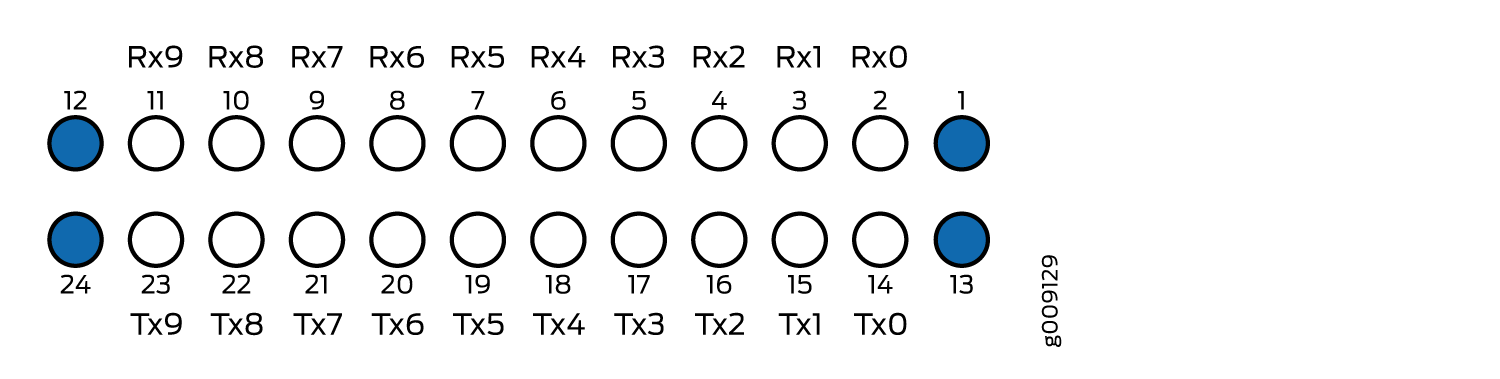
Ensure that you order cables with the correct polarity. Vendors refer to these crossover cables as key up to key up, latch up to latch up, Type B, or Method B. If you are using patch panels between two transceivers, ensure that the proper polarity is maintained through the cable plant.
The MPO optical connector for the CFP2-100G-SR10-D3 is defined in Section 5.6 of the CFP2 Hardware Specification and Section 88.10.3 of IEEE STD 802.3-2012. These specifications include the following requirements:
Recommended Option A in IEEE STD 802.3-2012.
The transceiver receptacle is plug. A patch cable with socket connector is required to mate with the module.
Ferrule finish shall be flat polished interface that is compliant with IEC 61754-7.
Alignment key is key up.
The optical interface must meet the requirement FT-1435-CORE in Generic Requirements for Multi-Fiber Optical Connectors. The module must pass the wiggle test defined by IEC 62150-3.
LC Duplex Connectors
You can use patch cables with LC duplex connectors to connect two supported transceivers of the same type—for example, 40GBASE-LR4-to-40GBASE-LR4 or 100GBASE-LR4-to100GBASE-LR4. The patch cable is one fiber pair with two LC duplex connectors at opposite ends. LC duplex connectors are also used with 12-fiber ribbon breakout cables, as described in 12-Fiber Ribbon Breakout Cables with MPO-to-LC Duplex Connectors.
Figure 2 shows an LC duplex connector being installed in a transceiver.