QFX5700 Site Preparation Overview
The following sections describe the guidelines, the specifications, and the requirements to install a QFX5700 switch.
QFX5700 Site Preparation Checklist
The checklist in Table 1 summarizes the tasks you must perform to prepare a site for the QFX5700.
✓ |
Item or Task |
For More Information |
|---|---|---|
| Environment | ||
□ |
Verify that environmental factors such as temperature and humidity do not exceed switch tolerances. |
|
| Power | ||
□ |
Measure the distance between external power sources and the switch installation site. |
|
□ |
Calculate the power consumption and requirements. |
|
| Rack | ||
□ |
Verify that your rack meets the minimum requirements for the installation of the switch. |
|
□ |
Plan rack location, including required space clearances. |
|
□ |
Secure the rack to the floor and building structure. |
|
| Cables | ||
□ |
Acquire cables and connectors:
|
The list of supported transceivers for the QFX5700 line cards is located at https://apps.juniper.net/hct/product/#prd=QFX5700. |
□ |
Plan the cable routing and management. |
QFX5700 Environmental Requirements and Specifications
The QFX5700 switch must be installed in a rack. It must be housed in a dry, clean, well-ventilated, and temperature-controlled environment.
Follow these environmental guidelines:
Ensure that the site is as dust-free as possible, because dust can clog air intake vents and filters, reducing the efficiency of the switch cooling system.
Maintain ambient airflow for normal switch operation. If the airflow is blocked or restricted, or if the intake air is too warm, the switch might overheat, leading to the switch temperature monitor shutting down the device to protect the hardware components.
Description |
Tolerance |
|---|---|
Altitude |
6000 ft (1828 m) |
Relative humidity |
55% to 70% (non-condensing) |
Non-operating temperature |
0° C to 40° C (32° F to 104° F) |
Shipping and storage temperature |
-40° C to 85° C (-40° F to 185° F) |
Pollution degree |
2 (IEC 60950) |
Acoustic noise level |
< 7.2 Bels (EN 300 753) |
Enclosure classification |
IP20 (IEC 60529) |
Seismic |
Tested and meets GR-63. |
Install QFX5700 switches only in restricted-access areas, such as dedicated equipment rooms and equipment closets, in accordance with Articles 110-16, 110-17, and 110-18 of the National Electrical Code, ANSI/NFPA 70.
QFX5700 General Site Guidelines
Efficient device operation requires proper site planning and maintenance and proper layout of the equipment, rack or cabinet (if used), and wiring closet.
To plan and create an acceptable operating environment for your device and prevent environmentally caused equipment failures:
Keep the area around the chassis free from dust and conductive material, such as metal flakes.
Follow prescribed airflow guidelines to ensure that the cooling system functions properly and that exhaust from other equipment doesn’t blow into the intake vents of the device.
Follow the prescribed electrostatic discharge (ESD) prevention procedures to prevent damage to the equipment. Static discharge can cause components to fail completely or intermittently over time.
Install the device in a secure area so that only authorized personnel can access the device.
QFX5700 Site Electrical Wiring Guidelines
Table 3 describes the factors you must consider while you plan the electrical wiring at your site.
It is particularly important to provide a properly grounded and shielded environment and to use electrical surge-suppression devices.
Site Wiring Factor |
Guidelines |
|---|---|
Signaling limitations |
To ensure that signaling functions optimally:
|
Radio frequency interference (RFI) |
To reduce or eliminate the emission of RFI from your site wiring:
|
Electromagnetic compatibility (EMC) |
Provide a properly grounded and shielded environment and use electrical surge-suppression devices. Strong sources of electromagnetic interference (EMI) can cause the following damage:
Tip:
If your site is susceptible to problems with EMC, particularly from lightning or radio transmitters, you might want to seek expert advice. |
The intrabuilding port(s) of the equipment or subassembly is suitable for connection to intrabuilding or unexposed wiring or cabling only. The intrabuilding port(s) of the equipment or subassembly MUST NOT be metallically connected to interfaces that connect to the OSP or its wiring. These interfaces are designed for use as intrabuilding interfaces only (Type 2 or Type 4 ports as described in GR-1089-CORE), and require isolation from the exposed OSP cabling. The addition of primary protectors is not sufficient protection to connect these interfaces metallically to OSP wiring.
QFX5700 Grounding Cable and Lug Specifications
For installations that require a separate grounding conductor to the chassis, the switch must be adequately grounded before power is connected to ensure proper operation and to meet safety and electromagnetic interference (EMI) requirements. To ground a QFX5700 switch, connect a grounding cable to earth ground, and then attach it to the chassis grounding point.
The switch is pluggable type A equipment installed in a restricted-access location. It has a separate protective earthing terminal provided on the chassis in addition to the grounding pin of the power supply cord. This separate protective earthing terminal must be permanently connected to earth ground for installations that require a separate grounding conductor to the chassis.
To comply with GR-1089 requirements, all intra-building copper cabling used for transceiver ports must be shielded and grounded at both ends.
Before switch installation begins, a licensed electrician must attach a cable lug to the grounding cables that you supply. A cable with an incorrectly attached lug can damage the switch.
You must ensure that all cables are rated for the environment in which they are deployed.
For a QFX5700 switch, you need a grounding cable and straight lug with dual holes. You also need a dual-hole straight lug connector. The grounding lug accommodates 4 AWG (25 mm²), minimum 90° C wire, or as required by the local code.
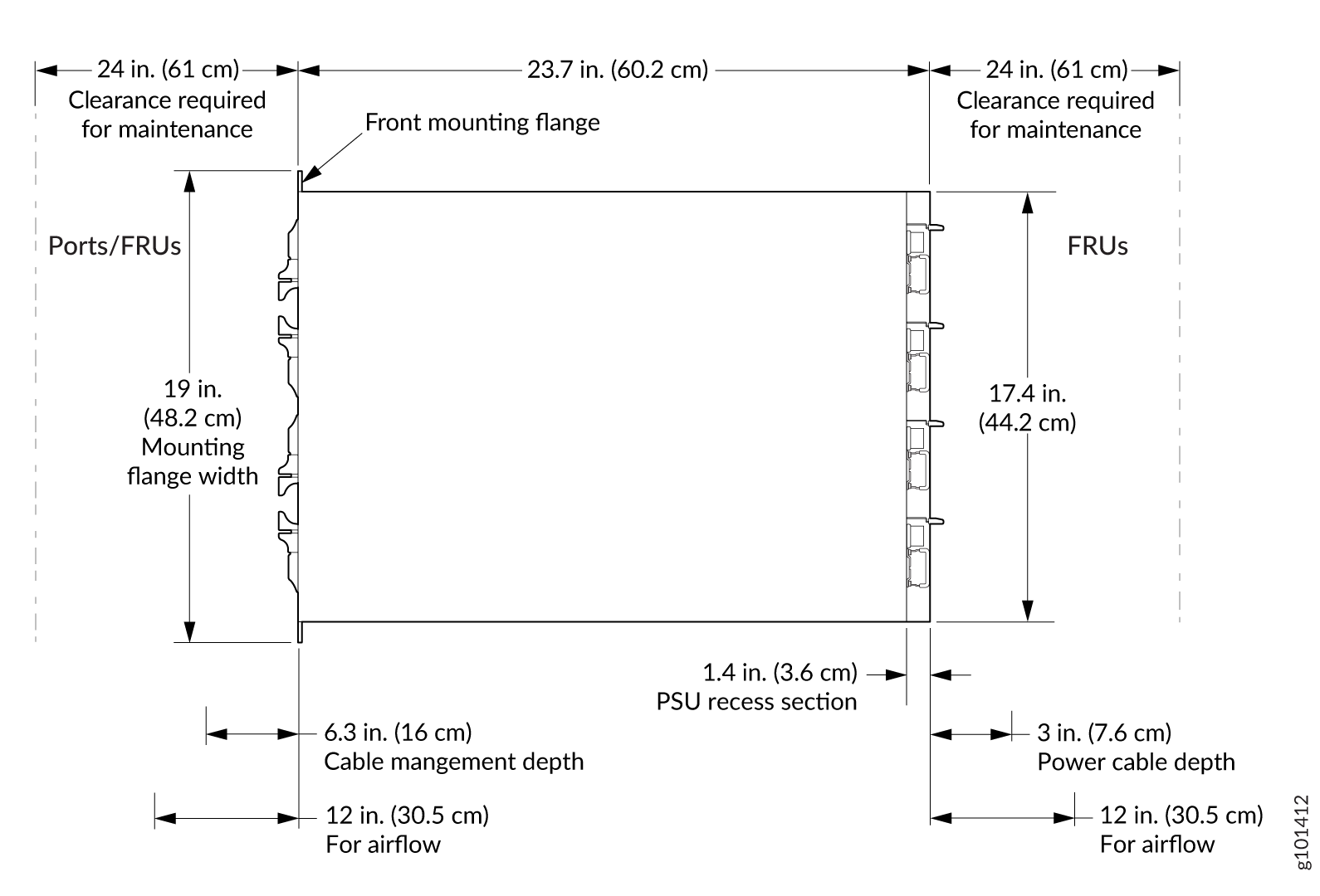
QFX5700 Clearance Requirements for Airflow and Hardware Maintenance
When you plan the site for a QFX5700 switch installation, you must allow sufficient clearance around the installed chassis for cooling and maintenance. See Figure 2 for a top view of clearance for the QFX5700.
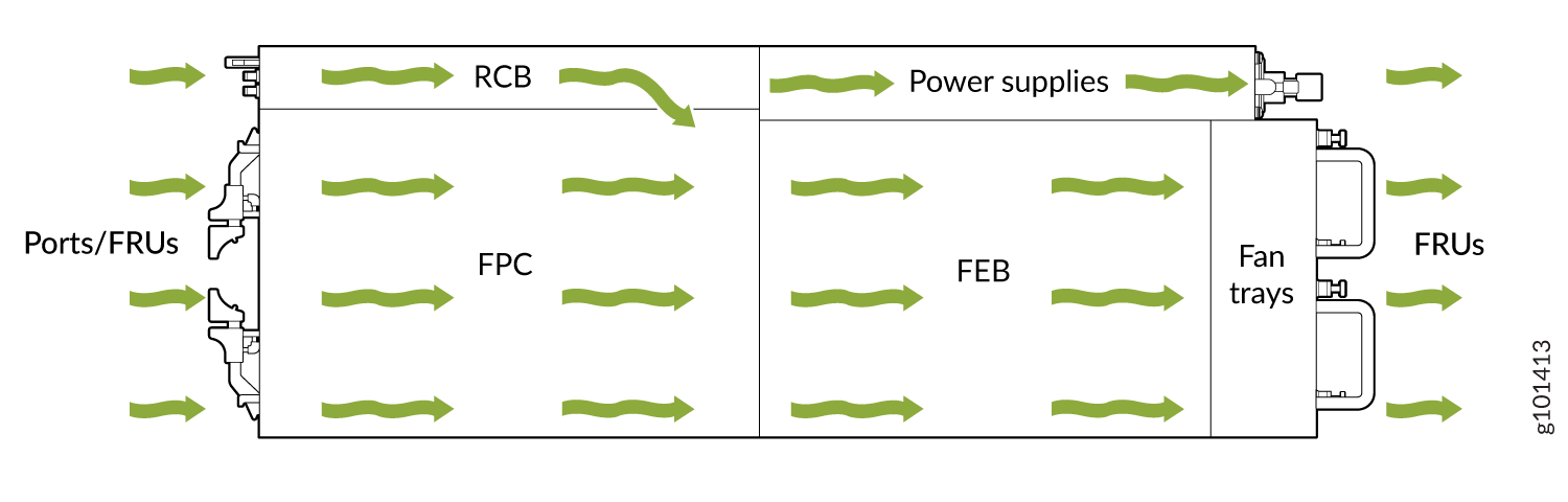
For the cooling system to function properly, the airflow around the chassis must be unrestricted. See for more information about the airflow through the chassis.
If you are mounting a QFX5700 switch in a rack or cabinet with other equipment, ensure that the exhaust from other equipment does not blow into the intake vents of the chassis.
For service personnel to remove and install hardware components, and to accommodate the interface and power cable bend radius, there must be adequate space at the front and rear of the switch. Allow at least 24 in. (61 cm) of space both at the front and the rear of the switch. NEBS GR-63 recommends that you allow at least 30 in. (76.2 cm) behind the switch.
The device must not interfere with the cooling of other systems in the rack. Fillers must be used as appropriate in the rack to ensure there is no recirculation of heated exhaust air back to the front of the rack. Care must also be taken around cables to ensure that there is no leakage of air in situations where recirculation might result.