Connect the QFX5700 to Power
To connect power to a QFX5700 switch, read the following procedures.
Do not mix power supply models in the same chassis in a running environment.
Connect the QFX5700 Switch to Earth Ground
To meet safety and electromagnetic interference (EMI) requirements and to ensure proper operation, you must connect the chassis to earth ground before you connect it to power.
You must install the QFX5700 in a restricted-access location and ensure that the chassis is always properly grounded. The QFX5700 has a two-hole protective grounding terminal provided on the chassis. Under all circumstances, use this grounding connection to ground the chassis. For AC-powered systems, you must also use the grounding wire in the AC power cord along with the two-hole grounding lug connection. This tested system meets or exceeds all applicable EMC regulatory requirements with the two-hole protective grounding terminal.
If an external ground connection is required, ensure that a licensed electrician has attached an appropriate grounding lug to the grounding cable you supply. Using a grounding cable with an incorrectly attached lug can damage the switch.
Mount your switch in the rack before attaching the grounding lug to the switch.
Ensure that you have the following parts and tools available:
An electrostatic discharge (ESD) grounding strap (provided).
Protective earthing terminal lug (provided).
Grounding cable for your QFX5700 (not provided)—The grounding cable must be 4 AWG (21.1 mm²) stranded wire should be rated 90° C or per local electrical code.
Grounding lug for your grounding cable (not provided)—This bracket attaches to the lower left corner of the switch chassis next to the bottom power supply, providing a protective earthing terminal for the switch. The grounding lug required is a Panduit LCD4-14A-L or equivalent.
A number 3 Pozidriv or Phillips screwdriver (not provided) to tighten the two screws that are mounted on the chassis.
You need to use terminal lugs that are Panduit LCD4-14A-L, or equivalent, and sized for 4 AWG (21.1 mm2) power source cables. The 4 AWG (21.1 mm²) stranded wire should be rated 90° C or per local electrical code. We recommend that you install heat-shrink tubing insulation around the crimped section of the power cables and lugs.
An AC-powered QFX5700 gets additional grounding when you plug the power supply in the switch into a grounded AC power outlet by using an AC power cord appropriate for your geographical location.
To connect earth ground to a QFX5700:
- Wrap and fasten one end of the ESD grounding strap around
your bare wrist and connect the other end of the strap to one of the
ESD points on the chassis. See Figure 1.Figure 1: ESD Point for the QFX5700
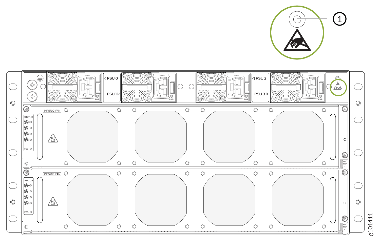 1—
1—ESD point
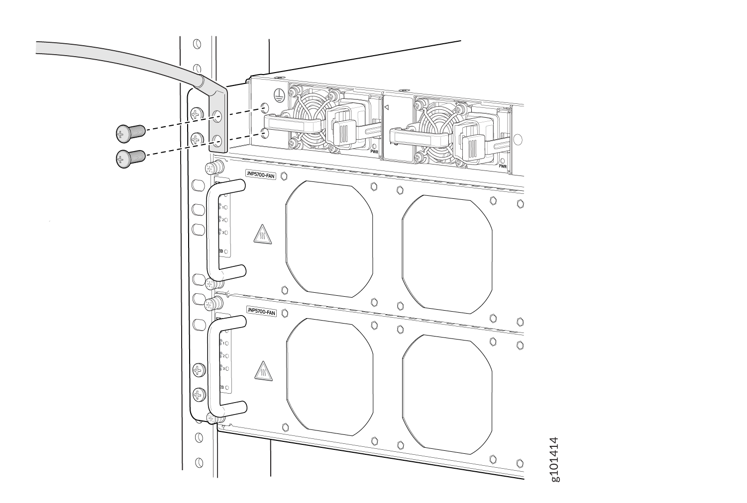
- Place the chassis grounding lug and cable over the screw
holes with the cable connection pointing to the left. See Figure 2.Figure 2: Connect a Grounding Cable to the QFX5700
Connect AC Power to a QFX5700
Before you begin to connect power to the switch, be sure you understand how to prevent ESD damage. See Prevention of Electrostatic Discharge Damage.
To meet safety and electromagnetic interference (EMI) requirements and to ensure proper operation, you must connect the QFX5700 switch to earth ground before you connect it to power.
Before you connect power to the switch, a licensed electrician must attach a cable lug to the grounding and power cables that you supply. A cable with an incorrectly attached lug can damage the switch (for example, by causing a short circuit). To meet safety and electromagnetic interference (EMI) requirements and to ensure proper operation, you must connect the chassis to earth ground before you connect it to power. For installations that require a separate grounding conductor to the chassis, use the protective earthing terminal on the switch chassis to connect to the earth ground. The switch gains additional grounding when you plug the PSM in the switch to a grounded AC power outlet by using the AC power cord appropriate for your geographical location.
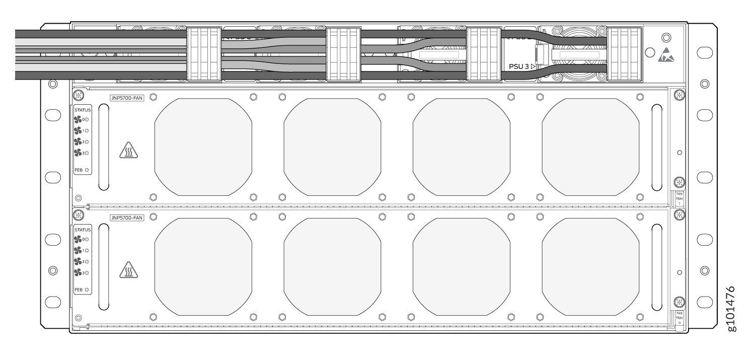
The AC power supply unit (PSUs) in an QFX5700 switch is a hot-removable and hot-insertable field-replaceable unit (FRU). You can remove and replace it without powering off the switch or disrupting routing functions. Since the power supplies in the QFX5700 switch aren't zoned, any 2 slots can be used to place PSUs in its chassis.
To connect AC power to a QFX5700 chassis:
To connect AC power to a QFX5700 switch:
Wrap and fasten one end of the ESD wrist strap around your bare wrist, and connect the other end of the strap to the ESD point on the device.
Ensure that the power supplies are fully inserted in the chassis and the latches are secure.
Locate the AC power cords shipped with the QFX5700 switch; the cords have plugs appropriate for your geographical location.
Insert the coupler end of the power cord into the AC power cord inlet on the AC power supply faceplate.
Figure 3: Connecting an AC Power Cord to the QFX5700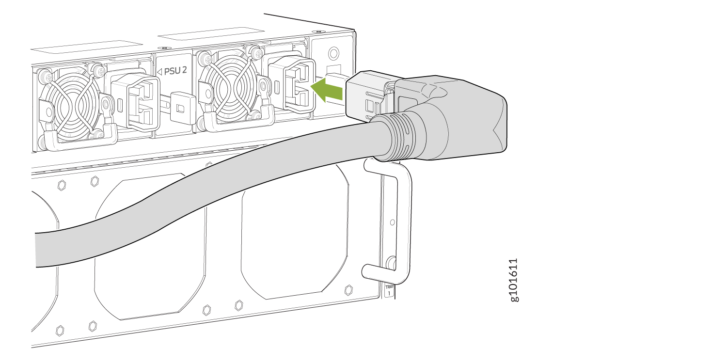 Figure 4: Connecting an AC Power Cord to the QFX5700
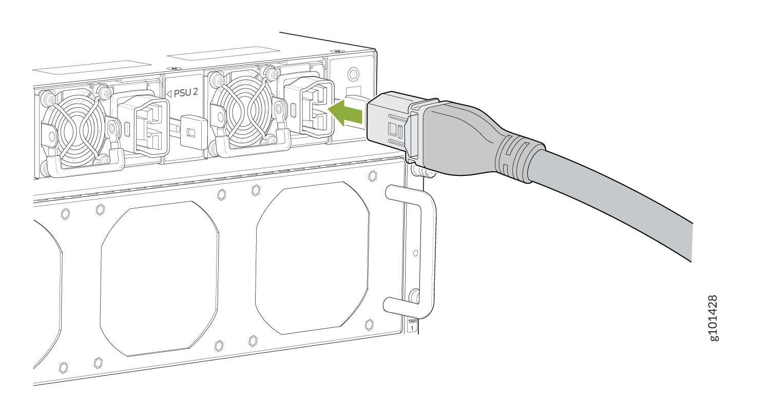
If the AC power source outlet has a power switch, set it to the off (O) position.
Note:The QFX5700 powers on as soon as power is provided to the power supply unit. There is no power switch on the power supply unit.
Insert the power cord plug into an AC power source outlet.
If the AC power source outlet has a power switch, set it to the on (|) position.
Verify that the status LEDs on each power supply are lit green. Verify that the status LEDs on each power supply are lit green
Connect DC Power to a QFX5700
The DC power supply units (PSUs) in an QFX5700 switch is a hot-removable and hot-insertable field-replaceable unit (FRU). You can remove and replace it without powering off the switch or disrupting routing functions. Since the power supplies in the QFX5700 switch aren't zoned, any 2 slots can be used to place PSUs in its chassis.
DC-powered QFX5700 switches are intended for installation only in a restricted-access location.
The battery returns of the DC power supply must be connected as an isolated DC return (DC-I).
To connect DC power to a QFX5700 chassis:
- Read the following:
DC Power Electrical Safety Guidelines
DC Power Copper Conductors Warning
DC Power Disconnection Warning
DC Power Grounding Requirements and Warning
Ensure that you have taken the necessary precautions to prevent electrostatic discharge (ESD) damage
Ensure that you have an ESD grounding strap.
If not already installed, install the DC power supplies in the switch.
Ensure that you have the following parts and tools available:
Phillips (+) screwdriver, 1/4-in., with a torque range between 6 lb-in. (0.68 Nm) and 7 lb-in. (0.79 Nm) (not provided)
Power cable or cables appropriate for your geographical location to connect DC power to the QFX5700. We recommend you use a 4 AWG gauge DC power cable such as a Panduit/LCDX4-14AH-L. The cable lugs are provided with the power supplies.
Note:Each power supply unit must be connected to a dedicated power source outlet.
To connect DC power to a QFX5700 switch:
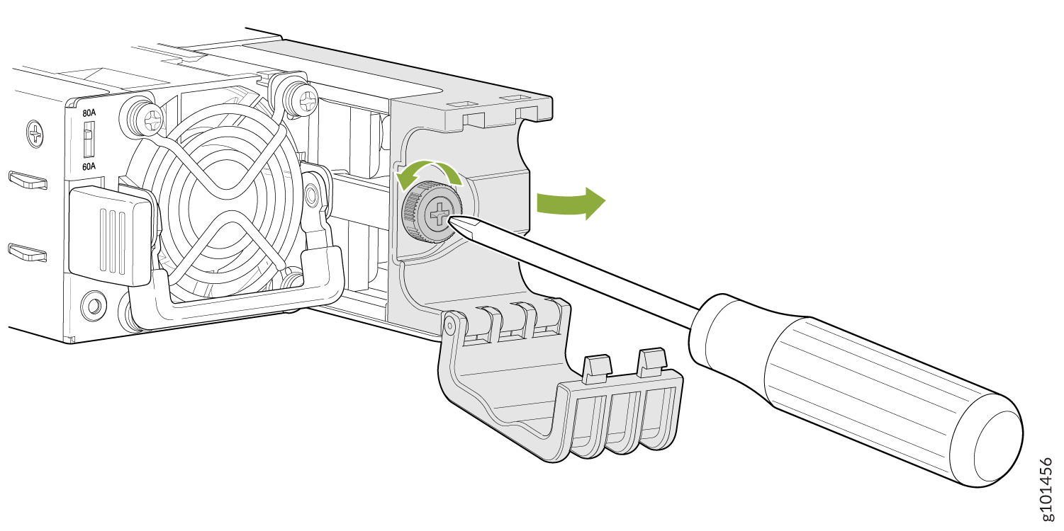
- Use a Phillips screwdriver to loosen the screw holding
the cable manager latch to the power supply terminal block cover.Figure 5: Removing the cable manager latch
-
Install heat-shrink tubing insulation around the power
cables.
To install heat-shrink tubing:
-
Slide the tubing over the portion of the cable where it is attached to the lug barrel. Ensure that tubing covers the end of the wire and the barrel of the lug attached to it.
-
Shrink the tubing with a heat gun. Ensure that you heat all sides of the tubing evenly so that it shrinks around the cable tightly.
Figure 6 shows the steps to install heat-shrink tubing.
Note:Do not overheat the tubing.
Figure 6: How to Install Heat-Shrink Tubing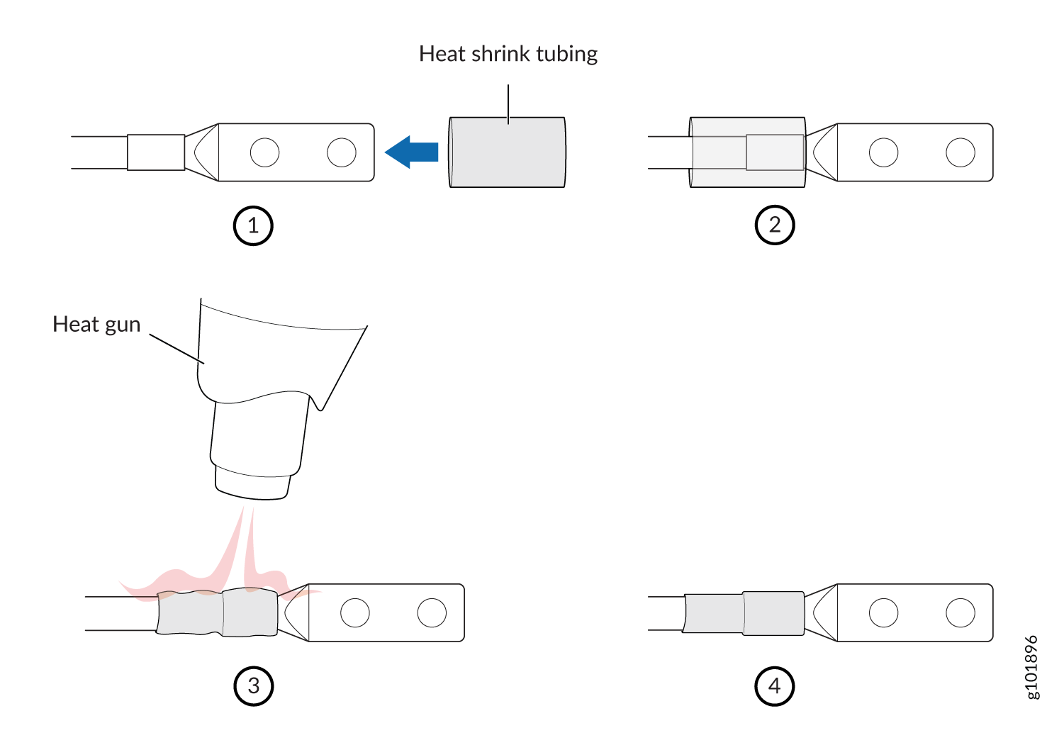
-
- Reattach the cable manager latch that you removed in Step"6"
and tighten the thumb screw.Figure 7: Reattaching the cable manager latch
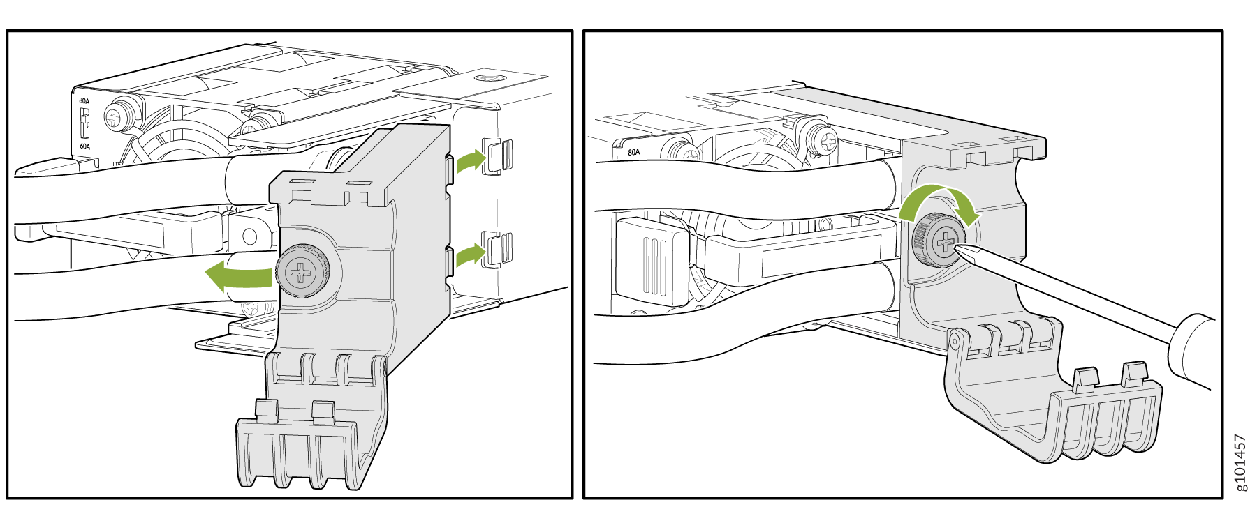
- Close the cable manager latch to hold the power cables
in place.Note:
Ensure that the power cables do not block access to device components or drape where people could trip over them.
Figure 8: Reattaching the cable manager latch