Help us improve your experience.

Let us know what you think.

Do you have time for a two-minute survey?


QFX5700 Cable Management System

The QFX5700 Cable Management System consists of the following components.

  • Cable Manager

  • Cable Manager Assembly

  • Tray

  • Locking mechanism

Note:

You need to necessarily attach the Cable manager assembly when you install six or more line cards of the same model.

The cable manager allows you to manage a large number of fiber-optic and copper cables attached to the RCBs and FPCs installed in the QFX5700 switch. It is installed in the front of the QFX5700 chassis. Figure 1 shows the QFX5700 Cable Manager.
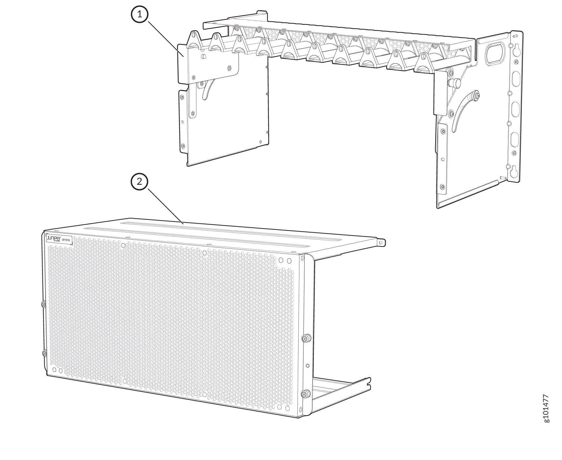
Figure 1: Cable Manager Rack mounting bracket assembly and Juniper network device with ventilation holes and logo for rack installation guide.
  1

Cable Manager Assembly

  2

EMI door

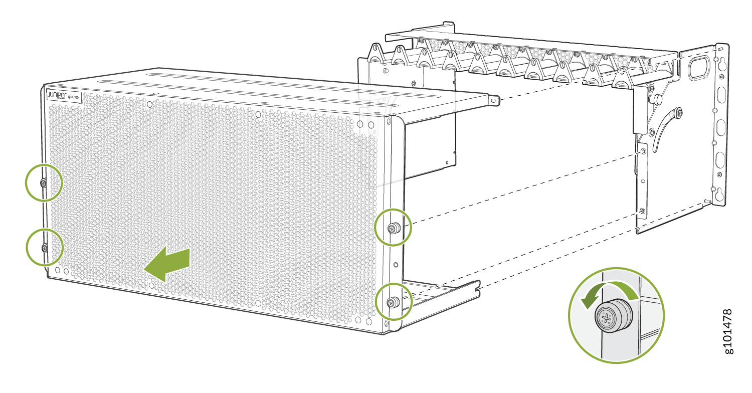
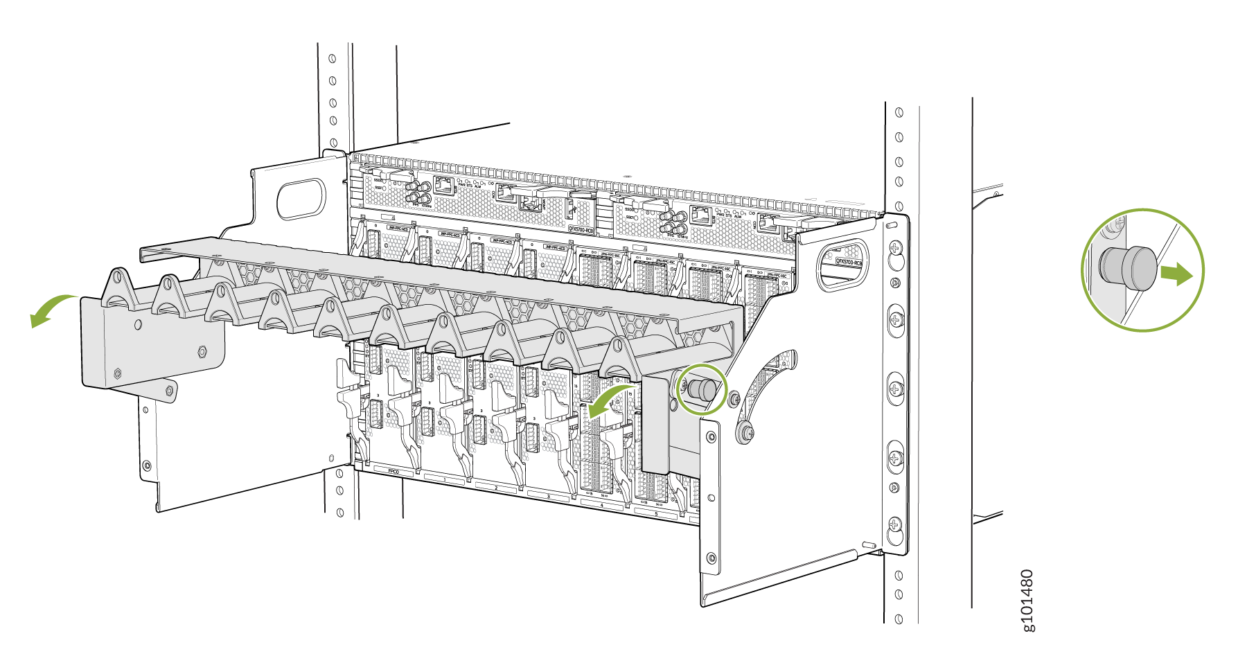
Before you install the cable manager assembly, you need to remove the EMI door. See Figure 2.

Figure 2: Remove the EMI Door Illustration of installing or removing front panel from a Juniper Networks device with highlighted screws and inset of screw turning direction.

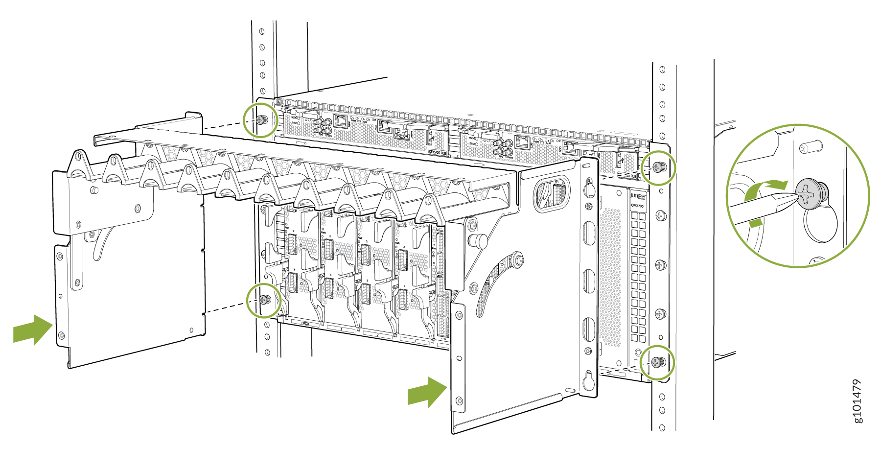
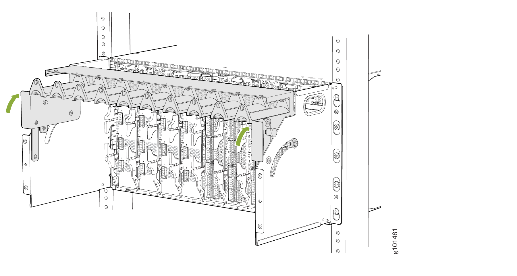
Now you can install the cable manager assembly. See Figure 3.

Figure 3: Install Cable Manager Assembly Installation or removal process of a network device with focus on mounting brackets, screws, and modular slots.

Pull out the spring-loaded pin on either sides of the cable manager and move the tray down to access RCB. See Figure 4.

Figure 4: Move the Tray to Access RCB Server rack illustration showing installation of a cable management arm. Arrows indicate movement direction. Inset details a securing latch.

You need to move the tray in order to access the FPC. See Figure 5.

Figure 5: Move the Tray to Access FPC Server rack illustration showing module installation with green arrows indicating movement direction for securing or releasing components.

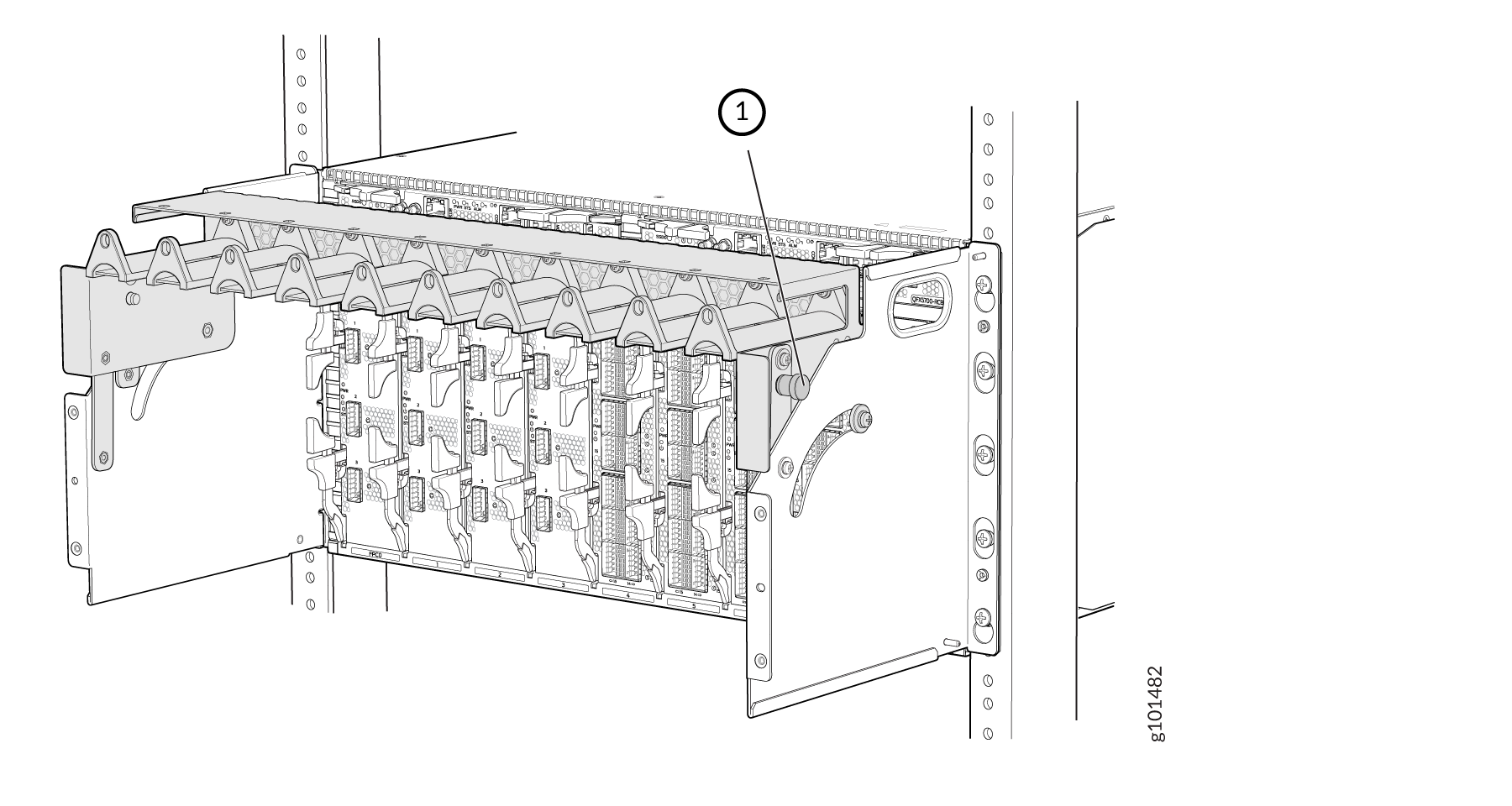
Now, lock the cable manager. See Figure 6.

Figure 6: Lock the Cable Manager Blade enclosure with numbered label pointing to cable management component in a server rack, part of a data center setup.

See Figure 7 and Figure 8 to understand how to route cables through the cable manager.

Figure 7: Route Cables through Cable Manager Internal layout of Juniper QFX5700 switch showing line cards labeled FPC, blue and yellow cabling, power indicators, cooling design, and management module.

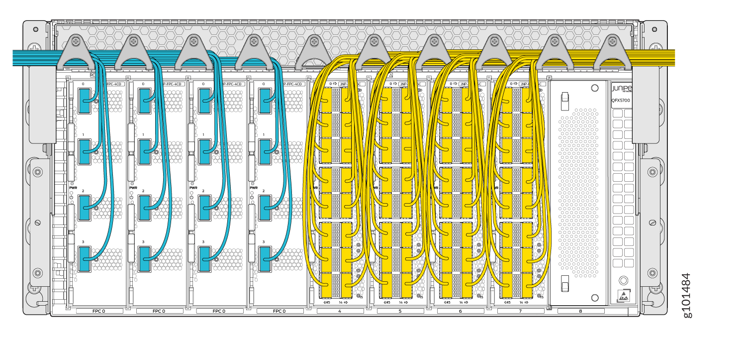
Once you have used the cable manager to router the cables, assemble the cable manager cover.

Figure 8: Assemble the Cable Manager Cover Juniper Networks QFX10000 series switch mounted in a rack with yellow and gray cables connected for data transmission.

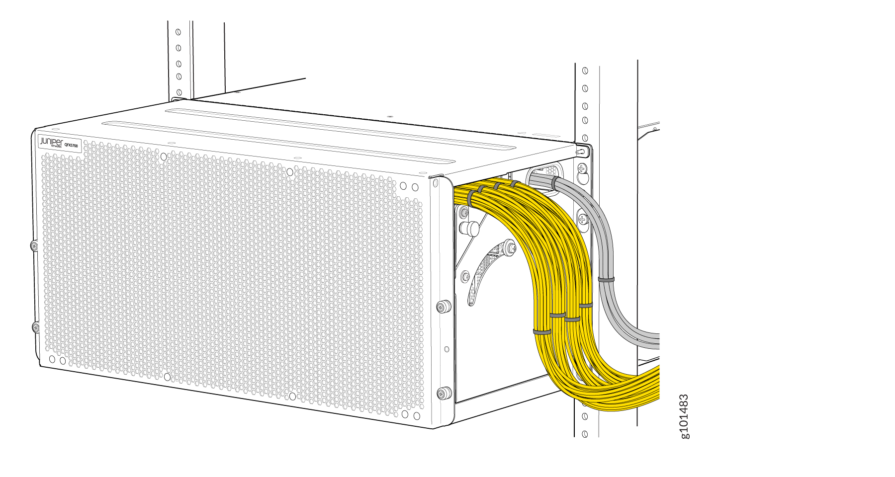
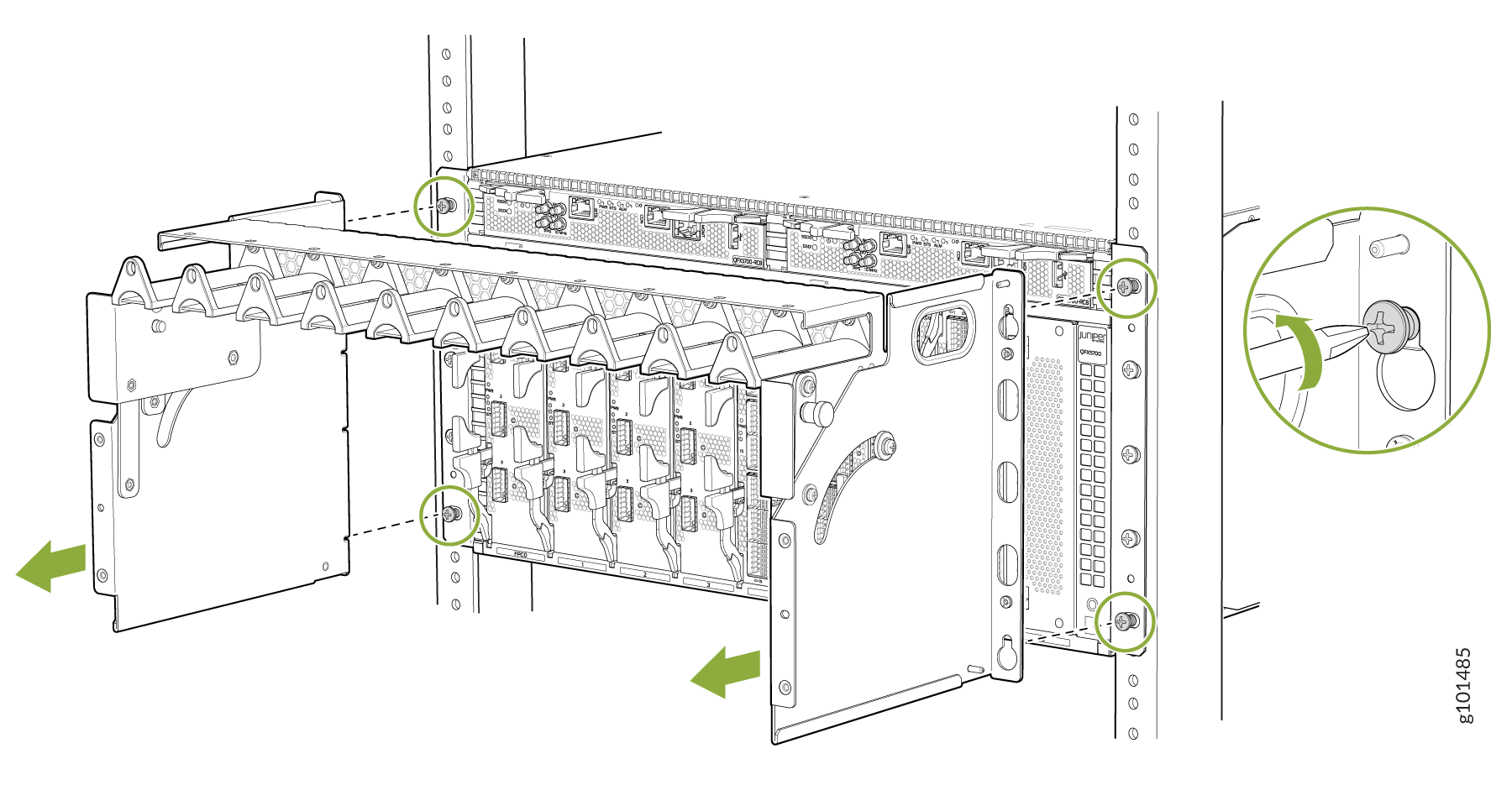
Figure 9 shows how you can remove the cable manager.

Figure 9: Remove Cable Manager Juniper Networks component installation in a rack with green arrows and circles indicating screw locations and locking mechanism.