QFX5700 Chassis
The switch chassis is a rigid sheet metal structure that houses all the other components (see Figure 1, Figure 2, Figure 3, Figure 4, and Figure 5. This topic provides more information about the physical specifications of the QFX5700 switch.
Before removing or installing components of a switch, attach an ESD strap to an ESD point and place the other end of the strap around your bare wrist. Failure to use an ESD strap can result in damage to the switch.
You must connect the router to an earth ground before you power it on and during normal operation.
QFX5700 Chassis Physical Specifications
The QFX5700 modular chassis is a rigid sheet-metal structure that houses the other switch components. See Figure 1 to help identify the major components. The chassis installs in standard 800-mm (or larger) enclosed cabinets, 19-in. equipment racks, or telco open-frame racks.
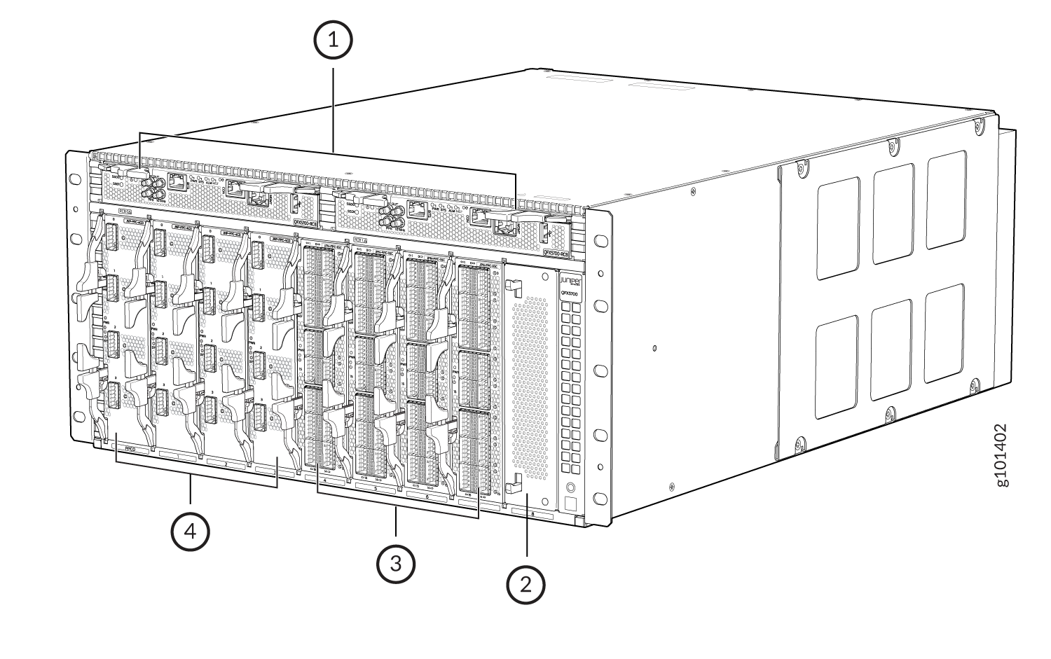
1 — RCB | 3 — FPC 4–7 |
2 — Unsupported slot | 4 — FPC 0-3 |
Figure 2 shows the front view of a fully configured QFX5700 chassis.
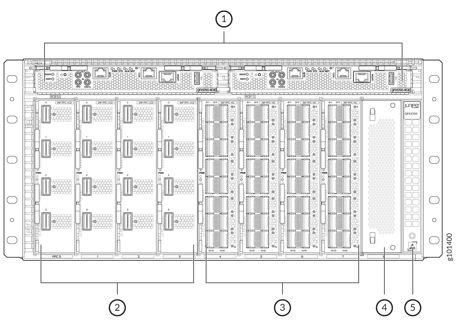
1 — RCB | 4 — Unsupported slot |
2 — FPC 0-3 | 5 — ESD Point |
3 — FPC 4-7 |
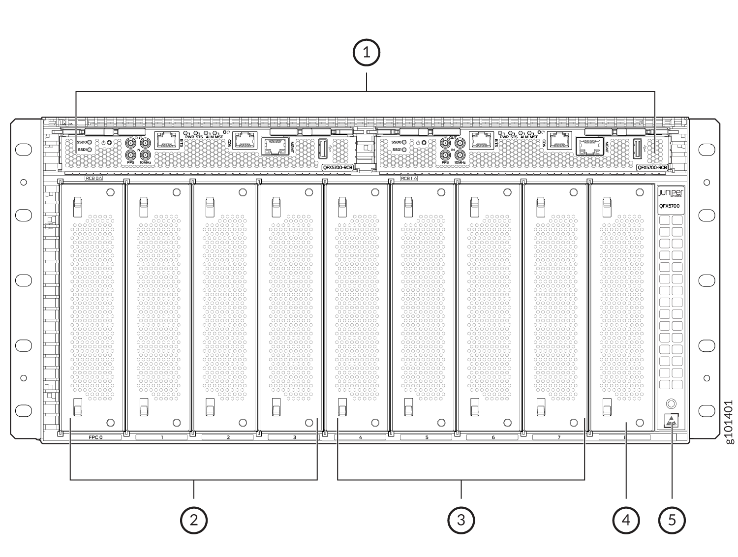
1 — RCB | 4 — Unsupported slot |
2 — FPC 0-3 | 5 — ESD Point |
3 — FPC 4-7 |
Figure 4 shows the rear view of an AC-powered QFX5700 switch.
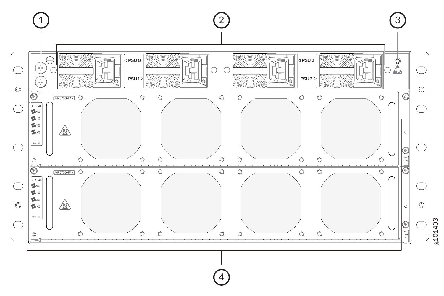
1 — Grounding Earth Terminal | 3 — ESD Point |
2 — AC/HVDC Power Supply Units | 4 — Fan Trays |
The handles on each side of the chassis facilitate the fine-tune positioning of the chassis on the base brackets. Do not use the handles to lift the chassis, even when the chassis is empty.
QFX5700 Physical Specifications
See to understand the physical specifications for the switch chassis and its components.
The QFX5700 is a 5U modular chassis and with the cable management system it is 6U.|
Description |
Weight |
Length |
Width |
Height |
|---|---|---|---|---|
|
Chassis (5 RU) |
Chassis Weight (with all FRUs installed) - 69.8 Kg. |
81.5 cm |
48.2 cm |
22.2 cm |
|
Routing and Control Board (RCB) |
1.2 kg |
(23.5 cm) |
(21.4 cm) |
(3.1 cm) |
|
Forwarding Engine Boards (FEBs) |
6.6 kg |
(28.1 cm) |
(43.7 cm) |
(8.4 cm) |
|
JNP-FPC-16C |
2 kg |
(25.8 cm) |
(18 cm) |
(4.5 cm) |
|
JNP-FPC-20Y |
2 kg |
(25.8 cm) |
(18 cm) |
(4.5 cm) |
|
JNP-FPC4CD |
2 kg |
(25.8 cm) |
(18 cm) |
(4.5 cm) |
|
AC power supply |
1.5 kg |
(31.5 cm) |
(7.4 cm) |
(4.4 cm) |
|
DC power supply |
1.5 kg |
(33.3 cm) |
(7.4 cm) |
(4.4 cm) |
|
Fan tray unit |
3.2kg |
(44 cm) |
(13.6 cm) |
(8.5 cm) |
|
Cable Manager Assembly |
8 kg |
(48.2 cm) |
(21.5 cm) |
(22.2 cm) |
QFX5700 Switch Midplane Description
The midplane is located on the rear of the chassis and forms the rear of the card cage. The Routing and Control Board (RCBs) and the Flexible PIC Concentrators (FPCs) are installed into the midplane from the front of the chassis, the Forwarding Engine Boards (FEBs), power supply units, and the fan trays install into the midplane from the rear of the chassis.
The midplane performs the following major functions: Provides a signal path—The midplane provides the signal path to the FPCs, RCBs, FEBs and other system components for monitoring and control of the system.
-
Provides a data path—Data packets are transferred across the midplane between the FPCs through the RCBs.
-
Distributes power—The power supplies connect to the midplane, which distributes power to all the switch components.
-
Provides a signal path—The midplane provides the signal path to the FPCs, RCBs, FEBs and other system components for monitoring and control of the system.