Multichassis Link Aggregation on Logical Systems Overview
On MX Series routers, EX9200, and QFX10000 switches, multichassis link aggregation (MC-LAG) enables a device to form a logical LAG interface with two or more other devices. MC-LAG provides additional benefits over traditional LAG in terms of node-level redundancy, multihoming support, and a loop-free Layer 2 network without running Spanning Tree Protocol (STP). The MC-LAG devices use Inter-Chassis Control Protocol (ICCP) to exchange the control information between two MC-LAG network devices. Starting in Junos OS Release 14.1, you can configure MC-LAG interfaces on logical systems within a router. Starting with Junos OS Release 15.1, you can configure MC-LAG interfaces on logical systems on EX9200 switches.
On QFX10008 switches, Layer 2 and Layer 3 IRB interfaces
are not supported under the [edit logical-systems] hierarchy.
To configure ICCP for MC-LAG interfaces on logical systems,
include the iccp statement at the [edit logical-systems logical-system-name protocols] hierarchy level.
To view ICCP information for MC-LAG on logical systems, use the show iccp logical-system logical-system-name command. To view ARP statistics or remote MAC addresses for
the multichassis aggregated Ethernet nodes for all or specified redundancy
groups on a logical system, use the show l2-learning redundancy-groups group-name logical-system logical-system-name (arp-statistics | remote-macs) command. To view neighbor
discovery (ND) statistical details for multichassis aggregated Ethernet
nodes on redundancy groups of a logical group, use the show
l2-learning redundancy-groups group-name logical-system logical-system-name nd-statistics command.
Logical systems enable effective, optimal segregation of a single router or switch into multiple virtual partitions, which can be configured and managed by diversified entities. Logical systems perform a subset of the actions of a physical router or switch and have their own unique routing tables, interfaces, policies, and routing instances. A set of logical systems within a single router or switch can handle the functions previously performed by several small routers or switches. As shown on the right side of Figure 1, a set of logical systems within a single router can handle the functions previously performed by several small routers.
In a network deployment that contains MC-LAG interfaces, you can configure such interfaces on logical systems contained within a router or switch. When you configure multichassis aggregated Ethernet interfaces on a logical system, you must ensure that these interfaces are added with the same multichassis aggregated Ethernet identification number and redundancy group identifier for the MC-LAG on both the peers or devices that are connected by the multichassis aggregated Ethernet interfaces. It is not necessary to specify the same logical system name on both the peers; however, you must ensure that ICCP to associate the routing or switching devices contained in a redundancy group is defined on both the peers within the logical systems of the devices. Such a configuration ensures that all the packets are transmitted using ICCP within the logical system network. The logical system information is added and removed by the ICCP process to prevent each packet from containing the logical system details. This behavior enables multiple disjoint users to employ MC-LAG capabilities within their networks transparently and seamlessly. A unique ICCP definition for a logical system is created, thereby enabling you to completely manage the ICCP parameters on one logical system without the need for access permissions to view other logical system networks on the same device. Configuration of MC-LAG interfaces on logical systems enables MC-LAG to be used across multiple routing tables and switch forwarding tables in active-active and active-standby modes of MC-LAG interfaces.
Because the Layer 2 address learning process supports logical systems, the ARP, neighbor discovery, and MAC synchronization packets that are traversing a multichassis aggregated Ethernet interface use the logical system:routing instance (LS:RI) combination to map the packets to the correct routing instance in a logical system. Link Aggregation Control Protocol (LACP) does not require the LS-RI combination to be identified because it operates on physical interfaces and is unique within a chassis. For a service, in the set of provider edge (PE) routers providing the service, the service ID distinguishes the routing instances in a logical system because it is unique for a logical system across a routing instance. MC-LAG is configured on the aggregated Ethernet (ae-) bundle interface. An ae- interface is a logical interface and is globally unique, which causes the MC-LAG configuration to be exclusive and separate for a router or switch. You can add ae- interfaces in an MC-LAG configuration to be part of a logical system and use it throughout that particular logical system.
Sample Configuration Scenario for MC-LAG on Logical Systems
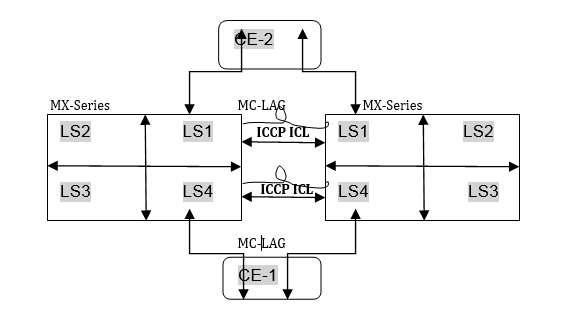
Consider a sample scenario in which two MX Series routers, MX1 and MX2, are connected using an aggregated Ethernet interface that is enabled with MC-LAG. The peers in an MC-LAG use an interchassis link-protection link (ICL-PL) to replicate forwarding information across the peers. Additionally, ICCP propagates the operational state of MC-LAG members through the ICL-PL. The two PE devices, MX1 and MX2, each have a LAG connected to the CE devices, CE1 and CE2. Four logical systems are defined on each of the PE devices, MX1 and MX2. CE-1 and CE-2 can be part of the same VLAN with the same VLAN ID and located in the same IP subnet for MC-LAG in two different logical systems. All four logical system entities can work independently in MX1 and MX2.
The ICCP process can manage multiple client-server connections with its peer ICCP instances based on the ICCP configuration for the logical system:routing instance (LS-RI) combinations. Each ICCP connection is associated with an LS-RI combination. For example, with two routing instances, IP1 and IP2, on each of the logical systems, LS1 and LS2, the following mapping is performed for ICCP settings:
[ICCP] (LS1) (IP1) < = = > (IP2) (LS1) [ICCP] within LS1 network.
[ICCP] (LS2) (IP1) < = = > (IP2) (LS2) [ICCP] within LS2 network.
An ICCP instance in a logical system is linked with the ICCP instance of the peer logical system. The ICCP application transmits the relevant routing index depending on the LS:RI combination to the BFD process, when BFD is configured in your topology.
Figure 2 shows the interconnection among logical systems on MX Series routers configured with MC-LAG.
The Layer 2 address learning process (l2ald) transmits and receives Address Learning Protocol (ARP), neighbor discovery, and MAC synchronization packets with the LS-RI information. When the peer MAC synchronization packets are received, l2ald decodes the logical system details from the packet and determines whether an identical logical system has been previously created on the router. If a match is found for the logical system, the MAC forwarding entry for the corresponding bridge table for an interface bridge domain is created. If the logical system in the received packet does not match the defined logical system on the device, for the MAC synchronization packet, the default logical instance is used for processing. Similarly, upon receipt of the ARP and neighbor discovery packets, l2ald decapsulates the logical system information from the packets and determines if the corresponding logical instance has been previously created. If a match is found for the logical system, the ARP and neighbor discovery packets are processed according to the Layer 3 index that is unique in the system. The programming kernel entry might not require any logical system information since it is programmed on a Layer 3 index which is unique in the system. If the logical system in the received packet does not match the defined logical system on the device, for the ARP and neighbor discovery packets, the default logical instance is used for processing. The routing instance is determined using the service ID attribute. The logical system information is forwarded to ICCP, which in turn identifies the appropriate ICCP interface for the logical system and sends packets over it.
Guidelines for Configuring MC-LAG on Logical Systems
Keep the following points in mind while configuring MC-LAG interfaces on logical systems:
You cannot use a single chassis to function as a provider edge (PE) device and a customer edge (CE) device in different logical systems.
You cannot use a single chassis to function as two PE devices by configuring logical systems on the chassis and ICCP. ICL links between the two logical systems because the multichassis aggregated Ethernet ID is unique in a router or switch.
Logical interfaces (IFLs) on the same
mc-aeinterface cannot be configured across multiple logical systems. In other words, in a multichassis link aggregation (MC-LAG) with both logical systems and logical interfaces (such asmc-ae ae0 unit 0), the same logical interface cannot be shared between logical systems.IGMP snooping in MC-LAG topologies with logical systems is not supported.
VPLS and VPN protocols with MC-LAG in active-standby mode is not supported.
Logical system information is not communicated to the peer chassis because this detail is derived from an ICCP instance.
Change History Table
Feature support is determined by the platform and release you are using. Use Feature Explorer to determine if a feature is supported on your platform.