Full Stack Design for WAN Edge Devices
Use this Full Stack guide to set up your Juniper WAN Edge devices in concert with Juniper Mist Access Points (APs) deployed in Wireless Assurance, and Juniper EX Series Switches deployed in Wired Assurance.
Overview
The Juniper Mist Full Stack enables you to expand your network capabilities by integrating Mist Access Points (APs), EX Switches, and WAN Edge devices. This design brings all your network devices into a cohesive onboarding, monitoring, and troubleshooting dashboard.
The Full Stack design begins with WAN Edge devices deployed in Mist WAN Assurance. After completing the Juniper Validated Design (JVD) topology (see SSR JVD and SRX JVD), you should already have a WAN Edge device deployed in a hub and spoke network. The WAN Edge device serves as the foundation for building out your entire network with the Full Stack. The Full Stack is specifically designed for a branch that utilizes Juniper equipment.
For successful implementation of the Full Stack, you'll need at least one Juniper EX Switch to onboard into the Mist cloud. If you plan to do advanced testing with virtual circuits, two EX Switches is ideal. Additionally, you can incorporate a Mist AP into the setup to enhance the wireless capabilities of the network. Onboarding those into your LAN network for Mist management gives administrators the ability to monitor and manage their WAN Edges, switches, and APs all from the Mist dashboard.
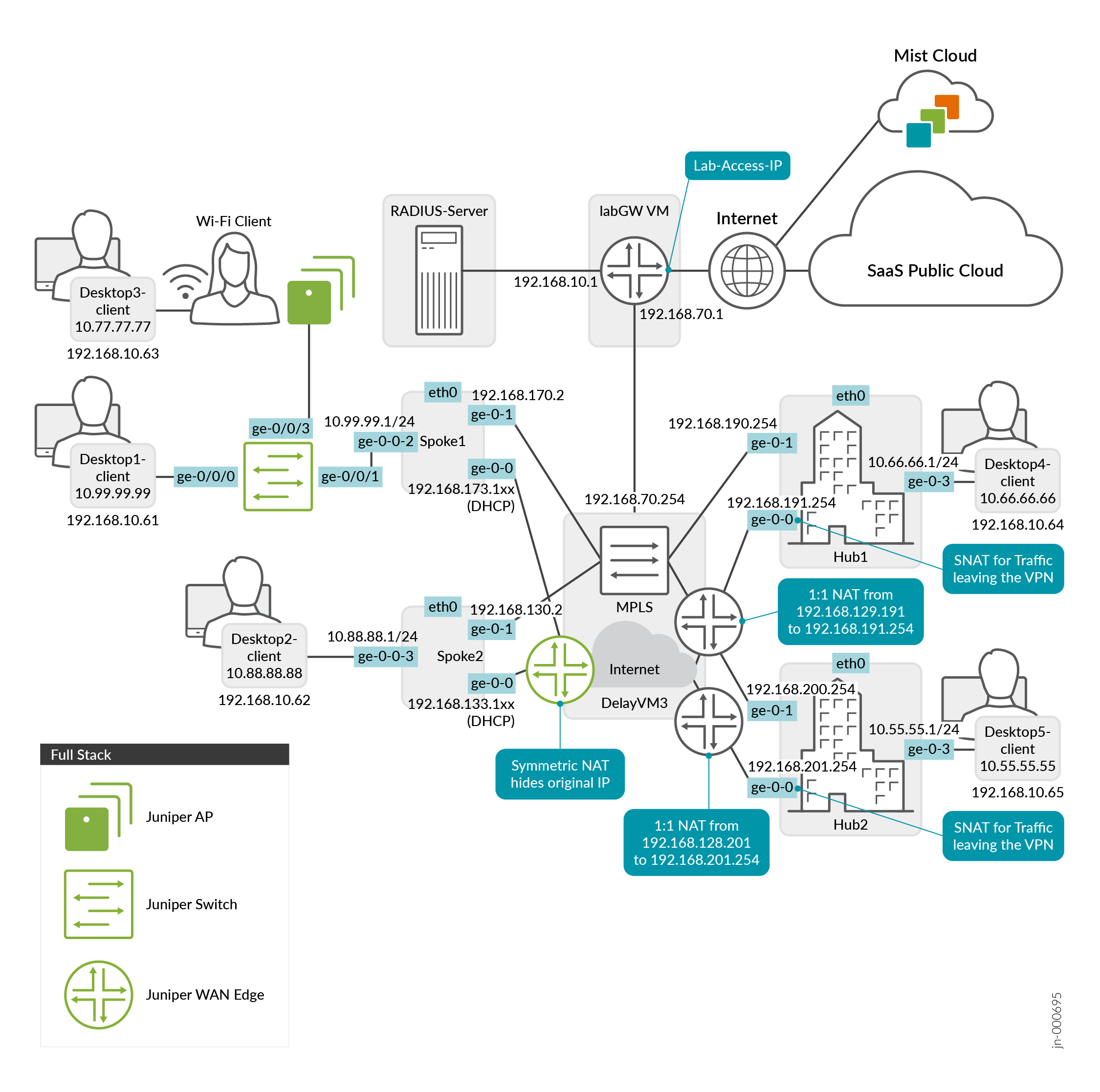
The Figure 1 shows the topology of the Juniper Mist Full Stack with WAN Assurance at its core. The devices in green are meant to show the different types of devices that make up a Full Stack. You can have a number of APs, Switches, and WAN Edges in a single Full Stack deployment.
Requirements and Considerations
To get started, you’ll need to alter some of the interfaces found in the Juniper Mist WAN Configuration Guide topology. We’ll show you how to do this using a Spokes configuration template found in the Mist WAN Configuration Guide. See WAN Assurance Configuration Overview.
Devices are expected to get out to the Mist cloud using the on-box Internet Service Provider (ISP) link. The device will attempt to retrieve a DHCP address from that ISP. Your devices will connect to Mist on these endpoints by default out of the box. However, if the device is behind a firewall, it may not be able to reach the Mist cloud. See Juniper Mist Firewall Ports and IP Addresses for Firewall Configuration for the firewall ports to open based on your device.
The device uses a hostname to connect on and needs to resolve that hostname using outbound DNS access to 8.8.8.8. Along with the previously mentioned DNS, the SSR will attempt to use 1.1.1.1 and the SRX will attempt to use 8.8.4.4. These are used as the DNS servers over the ISP link mentioned above to resolve the endpoints. Once the device connects to the Mist cloud, your configured DNS is used by the device.
If your SRX Series Firewall is showing as disconnected when it is online and reachable locally, you can troubleshoot the issue using Troubleshoot Disconnected SRX Series Firewalls.
Onboard a WAN Edge Device
Create a Site
Create a Hub Profile
You can also Create a Hub Profile by Cloning an existing one to save time.
You'll create hub profiles for WAN Edge devices at hub sites. You'll create WAN Edge templates for WAN Edge devices at spoke sites. Hub WAN interfaces create overlay endpoints for spokes. Spoke WAN interfaces map the appropriate Hub WAN interfaces, defining the topology. Hub profiles drive the addition and removal of paths on your overlay.
However, if your topology does not use an overlay, skip to the Create a New Spokes Configuration Template section below.
Create a New Spokes Configuration Template
The WAN Edge device at the spoke site in your Full Stack design is configured via the WAN Edge template. You can create a new spoke WAN Edge template, or clone an existing spoke template and then make the necessary changes.
The most efficient way to configure a WAN Edge template is to create a spoke WAN Edge Template from device-model. This automatically sets the configuration for you, and you can adjust the configuration in any way necessary.
-
In the Juniper Mist™ portal, click Organization >
WAN > WAN Edge
Templates.
A list of existing templates, if any, appears.
To learn how to create a spoke template, see Configure a WAN Edge Template.
Alternatively, device-specific templates automatically assign many aspects of the configuration, including WAN and LAN interfaces for connectivity as well as traffic steering profiles and applications policies to set rules for the traffic on your device.
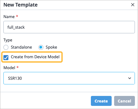
Note: The device-model template you select does not have to match the model of the device hardware itself. You are not confined to the configuration that device-specific templates automatically configure for you. You can customize the templates in any way that you need.To configure a device-specific template, navigate to Organization > WAN > WAN Edge Templates, then in the New Template pop-up window, enter a name, select a template type, and finally, select Create from Device Model.
-
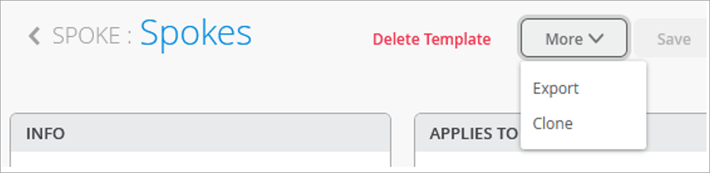
Optional: You can also clone an existing template. Click
More and select
Clone.
Figure 2: Selecting Clone Option for Template
-
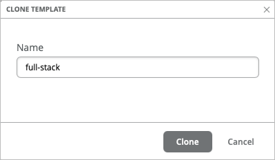
Enter a name, such as full-stack, and click
Clone.
Figure 3: Saving Cloned Template
 Tip:
Tip:Refresh your browser after cloning. This ensures objects displayed are truly refreshed.
-
Enter a name, such as full-stack, and click
Clone.
Edit the Template as Needed
-
On the WAN interface configuration section, edit or add any WAN interfaces
as needed.
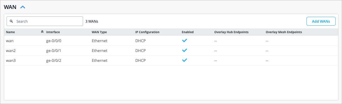 Note: The ge-0/0/0 WAN interface that was configured is what you plug into the ISP so that the ISP can then provide you with an address via DHCP. This DHCP address allows the device to use that provided WAN link to phone home to the Mist cloud to get the configuration from Mist using the ports and endpoints listed in Juniper Mist Firewall Ports and IP Addresses for Firewall Configuration.
Juniper Mist offers interface flexibility, meaning that you can have the same WAN interface configured on multiple devices. For example, you may want to configure the same interface on two different devices so that if one device fails, the other still has a physical link to your ISP. You can configure this in the Interface field of the WAN Configuration side-panel simply by entering comma separated values. This allows you to group these interfaces together to achieve redundancy.
-
On the LAN interface configuration section, note the LAN interface that got
configured.
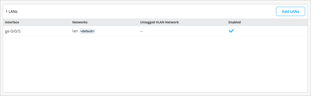 Select the LAN interface to open the Edit LAN Configuration side-panel.
Notice that the Network field is already configured with the LAN network. This is the network that automatically gets created as part of the device-model template and ensures that all of the devices in the Full Stack are able to access the Mist cloud in the same way using the same policies. There is a DHCP server running on this LAN interface that hands out addresses in the 192.168.1.0/24 address space.
You can navigate to the Network configuration from the left menu > Organization > Networks, then select the appropriate network.
Note: The Access to MIST Cloud checkbox is selected by default as part of the Network configuration. This setting allows other endpoints on the network to access the same services and policies that are built into the WAN Edge device so that the devices can automatically connect to the Mist cloud.If you navigated to the Network configuration, you can navigate back to the WAN Edge template, from the left menu, navigate to Organization > WAN Edge Templates, then select the appropriate template.
Figure 4: Modify LAN Interface Configuration
-
You may find that you need to add a guest network to a LAN interface to
allow guest users onto your corporate Wi-Fi. You first create the guest
network, then add a new LAN interface that you configure that guest network
on.
- Navigate to the left menu to Organization > WAN > Networks.
- In the top-right corner of the page, click Add Networks, then fill in the fields. You can use the samples in Table 1 below to guide you.
Table 1: Sample Guest Network Configuration Fields Field How to Configure Name Guest Subnet IP Address Enter the subnet IP address you want this network to use (Example: 172.16.1.0). Prefix Length Enter the prefix length for the IP Subnet (Example: 24) VLAN ID 100 Access to MIST Cloud checkbox Deselect the checkbox, as the guest network traditionally does not have devices that need to connect to the Mist cloud. 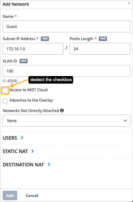
- Click Add from the bottom of the Add Network side-panel.
- Navigate back to the WAN Edge template.
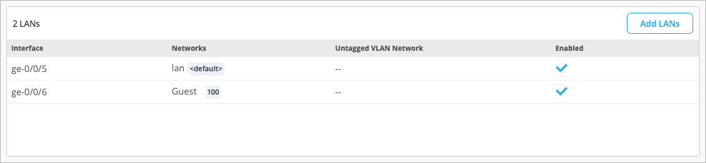
- From the LANs section, click Add LANs, then fill in the fields. You can use the samples in Table 2 below to guide you.
Table 2: Sample LAN Configuration Fields for Guest Network Field How to Configure Interface ge-0/0/6 Network Guest (select your newly created network from the drop-down list). 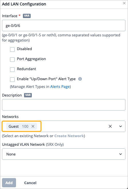 You must also create an Application Policy to allow guest traffic. Continue with the procedure to ensure completeness of your Full Stack design, then create an application policy as described in step 7 below.
- Click Add from the bottom of the Add LAN Configuration side-panel.
- Navigate to the IP Config section and click Add IP Config and add the guest network and the corresponding IP address.
-
Configure DHCP for the guest network. Navigate to the DHCP
Config section of the WAN Edge template.
- Click Add DHCP Config.
- Select the guest network from the Network dropdown. Configure the fields. You can use the samples in Table 3 below to guide you.
Table 3: Sample DHCP Configuration Fields for Guest Network Field How to Configure Name Guest DHCP Server IP Start Refer to the IP Start in this DHCP configuration (Example: 172.16.1.2). IP End Refer to the IP End in this DHCP configuration (Example: 172.16.1.254). Gateway Refer to the gateway address for this DHCP configuration (Example: 172.16.1.1). DNS Servers Refer to the DNS Server that your network will use to translate IP addresses (Example: 8.8.8.8,1.1.1.1). You should now see your new LAN configuration in the list.
 The guest network must also be configured on any switches and APs that are part of your Full Stack design.
 -
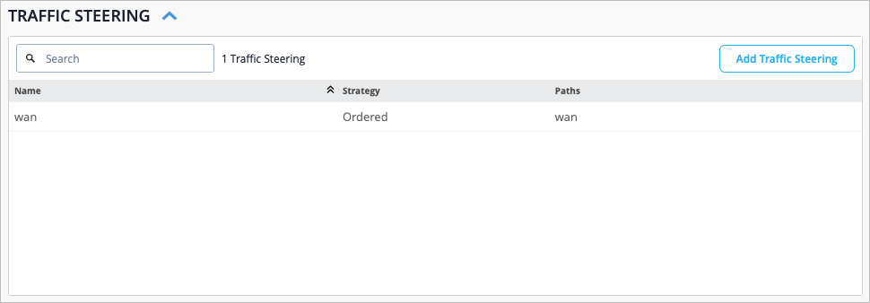
Navigate to the Traffic Steering section of the
template. Notice a traffic steering rule was configured for you already as
part of the device-specific template, and is configured to have traffic use
the WAN path.
Edit the existing traffic steering or add new traffic steering rules as needed.
Recall that there are multiple WAN interfaces configured as part of the device-specific template. You may find yourself using those other WAN interfaces when you configure a second WAN path in Traffic Steering. Or, you may find that you need to configure another traffic steering policy to send a certain type of traffic out of the other WAN link.
To learn how to create a new traffic steering policy, see Traffic Steering Rules and Configure Path Selection from Hub-to-Spoke with Traffic Steering.
-
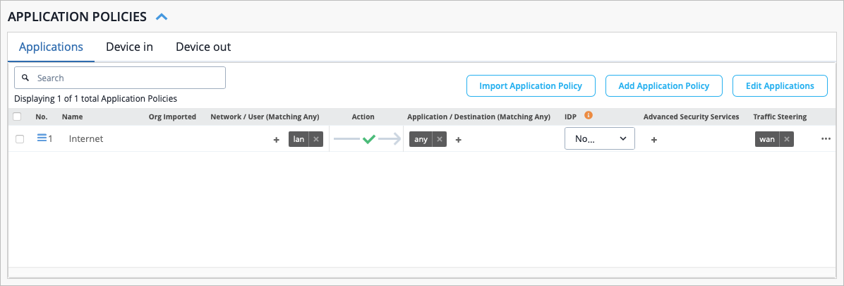
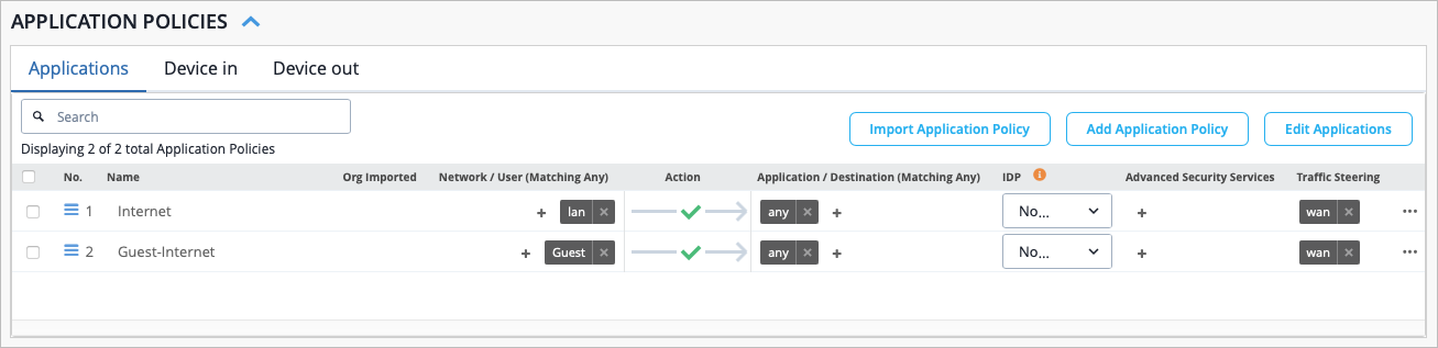
Navigate to the Application Policies section of the
template. If you used a device-specific template, notice that an application
policy was configured for you. You can edit this policy as needed, or you
can create a new one.
Figure 5: Application Policy Configuration
You must now create an application policy to allow guest traffic as per the Guest network configured in step 4 above. Examples are in the sample table below.
- From the Application Policies section, click Add Application Policy.
- Fill in the various fields. You can use the samples in Table 4 below to guide you.
Table 4: Sample Application Policy for Guest Network Traffic Field How to Configure Name guest-internet Network Guest Action Allow Application/Destination Any Traffic Steering wan You should now see your new application policy that allows guest traffic.
For more information on how to create a new application policy, see Application Policies.
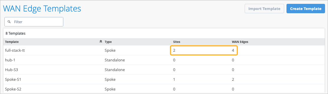
Assign the New Template to a Site
-
Review the Site column on the WAN Edge Templates page as shown in Figure
6.
Figure 6: Details of WAN Edge Template
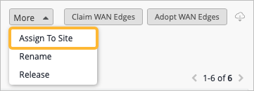
Assign the WAN Edge Devices to a Site
As part of completing the Full Stack design, you must now assign the WAN Edge devices to the same site you applied your template to in the previous section. This ensures that the WAN Edge devices in your Full Stack get the necessary configuration.
-
Click the More button in the top right corner of the
page, then select Assign to Site.
Add Your Switch to the Full Stack Design
Now it is time to onboard your switch and add it to your Full Stack design. For details on how to onboard your switch, refer to:
-
The product documentation for your switch in the Juniper TechLibrary.
-
To get a new cloud-ready EX switch up and running in the Juniper Mist cloud portal, follow the onboarding steps and links in Cloud-Ready EX and QFX Switches with Mist and Onboard Switches to Mist Cloud.
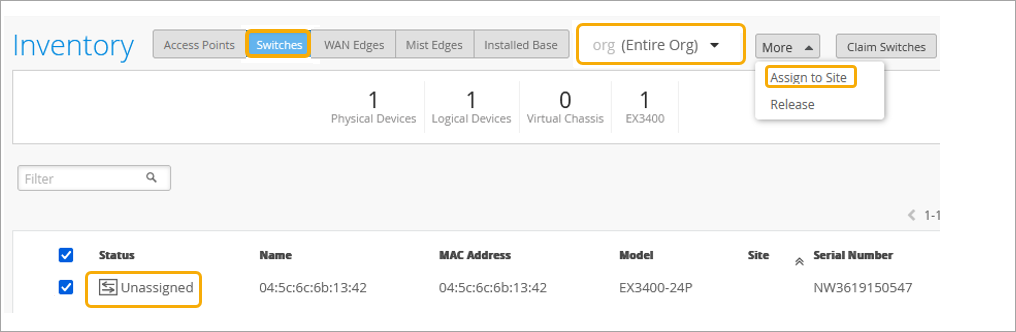
As part of completing the Full Stack design, you must now assign the switch to the same site as the other devices in the Full Stack, and must select the ports which the other devices will connect to your switch on. You must also configure the same guest network you configured on your WAN Edge.
-
In the Inventory page, ensure the inventory view is set to org
(Entire Org) so that you see all your devices.
Figure 7: EX Series Switch in Inventory
-
In the Assign Switches pop-up:
- Select the appropriate site.
- Disable the Manage configuration with Mist option. You can enable this option at a later stage if required.
Figure 8: Select the Site for the Switch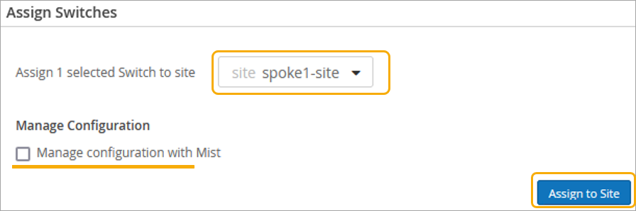
-
Confirm the change in the Assign Switches pop-up once you assign the device
to the site.
You can see the site name under New Site.
Figure 9: Assigned Switch to Site Details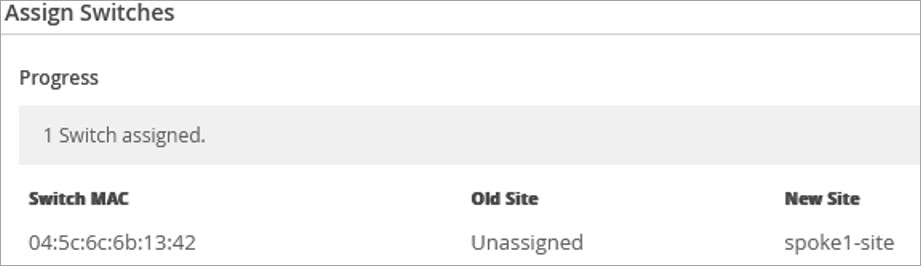
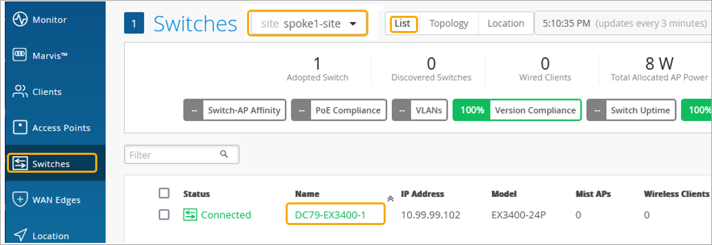
-
Click the switch to open the switch configuration page.
Figure 10: Select Assigned Switch for Modification
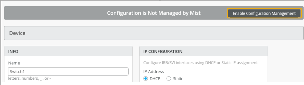
-
Verify the device name, then scroll down to the Switch
Configuration section and check Enable
Configuration Management.
Figure 11: Configuration of Assigned Switch
You must now select the ports the other devices in the Full Stack will use to connect to your switch.
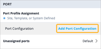
-
Navigate to the Port section, then click
Add Port Configuration.
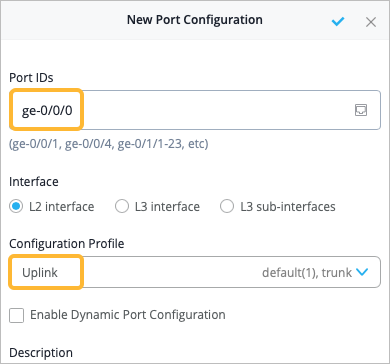
-
In the New Port Configuration page, configure the following options to
indicate the port the other devices will connect to the switch on:
-
Set the Port IDs as ge-0/0/0.
-
Select the existing Configuration Profile as Uplink, then select the checkbox to save the changes.
-
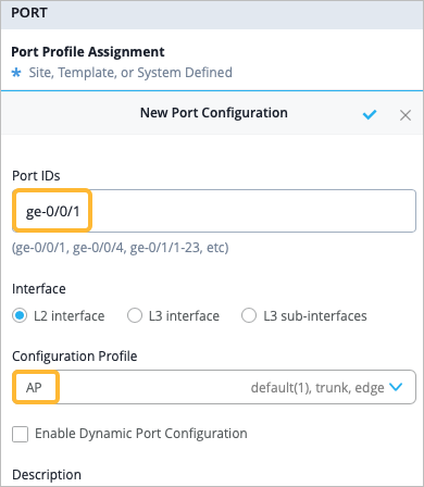
-
Add another port configuration, this time for your AP. Click Add
Port Configuration, then:
-
Set the Port IDs as ge-0/0/1.
-
Select the existing Configuration Profile as AP. Select the checkmark to save the changes.
-
-
Navigate to the Networks section and click Add
Network to add the same guest network you configured on your
WAN Edge. You can use the samples in Table 5 below to guide
you.
Table 5: Sample Guest Network Configuration in Switch Templates Field How to Configure Name Guest VLAN ID 100 IPv4 Subnet Enter the subnet IP address you want this network to use (Example: 172.16.1.0). 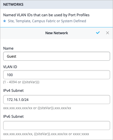
Add Your APs to the Full Stack Design
Now it is time to onboard your AP and add it to your Full Stack design. Refer to:
-
The product documentation in the Juniper TechLibrary for details on how to onboard your AP.
- For the steps to get a new AP up and running in the Mist cloud, see the Juniper Mist Access Points Quick Start Guide.
To complete the Full Stack design, you must now assign the switch to the same site as the other devices in the Full Stack. You must also configure your AP with the same guest network you configured on your WAN Edge and switch.
-
Add the same guest network you created in the previous steps. You can use
the samples in Table 6
below to guide you. For more information on how to configure WLAN templates,
see Configure a WLAN Template, Adding a WLAN, and WLAN Options.
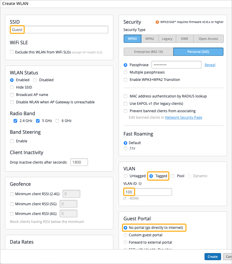
Table 6: Sample Guest Network Configuration in WLAN Templates Field How to Configure SSID Guest Security Type Choose a security type that best fits your deployment.
VLAN Tagged VLAN ID 100 Guest Portal If guest users on your network will need to sign in to get internet access, make the appropriate selection. For example, you can Add a Custom Guest Portal to a WLAN, Use an External Portal for Guest Access, or Use an Identity Provider for Guest Access.