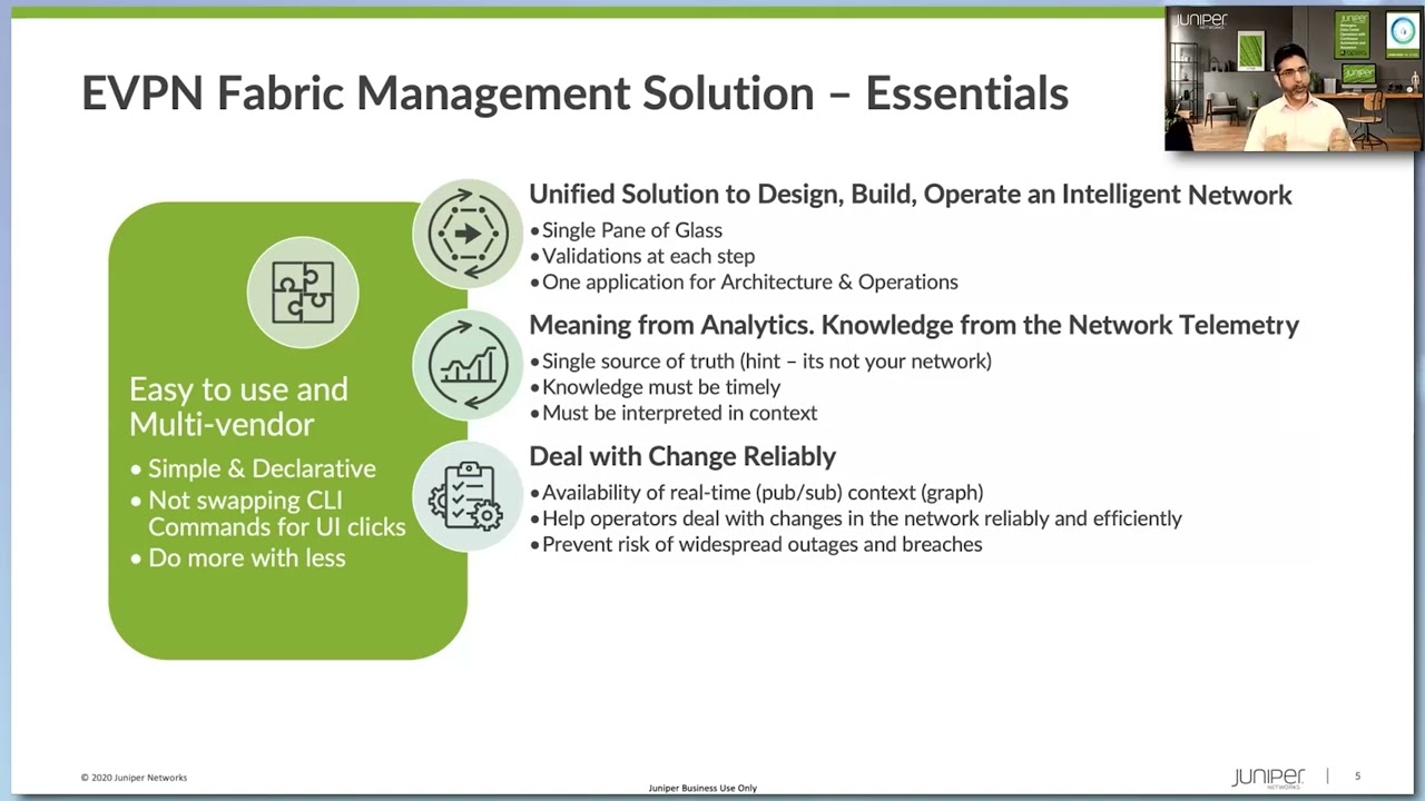
Data Center Filter-Based Forwarding: Verification

Juniper Learning Byte: Zach Gibbs demonstrates how to verify filter-based forwarding.
This Learning Byte is an educational demo that walks you step by step through the verification process for filter-based forwarding. This video is most appropriate for users with a high degree of knowledge and skill with data center technologies.
You’ll learn
An example of the topology, which includes two routers, the service leaf and the data center firewall
How to inspect the traffic going from Host1 to Host2
How to permit SSH traffic and block ICMP traffic
Who is this for?
Host
Transcript
0:00 [Music]
0:11 hello my name is zach gibbs and i'm a
0:14 content developer within education
0:16 services inside juniper networks and
0:19 today we will be going through the data
0:21 center filter-based forwarding
0:22 verification learning by
0:25 all right so here is our topology and in
0:28 this topology we have a few different
0:30 devices we have router l1 and router l2
0:33 which act as router leafs and then we
0:36 have service leaf l1 which is our server
0:38 sleeve and dcfw which is the data center
0:42 firewall
0:43 and so one thing to keep in mind here is
0:45 that there are other learning bytes that
0:47 i've done that cover the configuration
0:49 of those devices
0:51 and so if you're interested in that the
0:53 configuration of filter-based forwarding
0:56 in a data center go ahead and check
0:57 those out but with this learning byte
0:59 we're going to focus on the verification
1:01 making sure this actually works because
1:03 remember we are sending traffic from
1:05 host one to host two however we want
1:07 that traffic to be inspected and we're
1:10 going to be permitting ssh traffic and
1:13 blocking and logging icmp traffic so
1:15 with that being said let's get this
1:17 going
1:18 okay so here is the topology so what
1:20 have we done so far we've configured the
1:22 inspect vrf
1:24 on router l1 which is a normal router
1:26 leaf and then inspect vrf on service l1
1:29 which is the service leaf the secure vrf
1:31 on service l1 and the secure vrf on
1:35 router l2 and then we did some security
1:37 policy configuration and looked at the
1:39 dc firewall uh to show how things are
1:42 working there we looked at the bgp
1:44 things like that are the bgp sessions to
1:46 make sure they're up and functioning
1:47 which they are make sure we're getting
1:48 routes and advertising the routes we
1:49 want to do so things look pretty good
1:52 there so let's go ahead and jump back to
1:53 host one
1:55 and see what happens when we attempt to
1:57 communicate with host two
1:59 and before we do that though i would
2:01 like to clear the syslog file
2:06 just uh make sure we
2:08 don't have anything extra in there
2:10 okay so let's go ahead and attempt to
2:12 ping host one from host two and this
2:15 should not work recall we are blocking
2:17 this traffic and so that's great now
2:18 let's open an ssh session
2:22 and good we get prompted for the
2:24 password and good we're we are in host
2:27 two
2:28 and we are currently
2:29 logged in to host one or at least the
2:31 initial session is host one but we're
2:34 able to open a ssh session from host one
2:36 to host two so that's perfect so let's
2:38 go ahead and leave that open for now and
2:40 then let's jump back to router l1 to
2:42 verify what we're seeing so
2:45 here is the router leaf router l1 and so
2:48 recall we set up that firewall filter
2:51 with a
2:52 counter and we can see here the counter
2:54 okay great
2:55 that looks good so we have traffic now
2:57 let's create a little more traffic let's
2:59 jump back to host one and create a
3:00 little more traffic here
3:02 let's look at stuff
3:05 do a few returns that'll create some
3:06 traffic just to make sure that is
3:08 incremented because we want that to be
3:09 incrementing and great we went from 37
3:11 to 56
3:12 so we definitely have traffic hitting
3:14 that firewall filter that is perfect
3:16 that's exactly what we want to see
3:18 and so let's go ahead and jump to
3:21 router l2
3:23 so here is router l2 let's do the same
3:25 thing
3:27 look at the firewall and we see this is
3:29 host 2 to host 1
3:31 and so this is the return traffic when
3:32 you see we have 40 packets here it's not
3:34 going to be symmetrical because ssh
3:36 isn't symmetrical it's not like we're
3:37 doing ping traffic here so let's jump
3:39 back to host one create a little more
3:40 traffic
3:42 okay so
3:43 created some traffic let's look at
3:44 router l2
3:46 and recall this is the device connected
3:48 to the leaf connector to host too
3:51 and great it is incrementing the return
3:53 traffic is hitting that firewall filter
3:54 getting sent to the vrf perfect so let's
3:57 look at let's jump back to
3:59 router l1
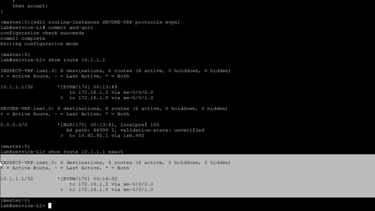
4:01 and let's look at the
4:03 the route for host 2. see what we have
4:05 here
4:07 vrf1 has a direct route to it that's
4:10 perfect that's that's how that should be
4:12 that's just standard erb and
4:15 then and because that's because it's set
4:17 up with that irb20 that's in that same
4:19 subnet and then in the inspect vrf we
4:21 have a default route and that is learn
4:23 through evpn that is perfect and those
4:26 two interfaces point to uh spine devices
4:30 they haven't really talked about the
4:31 spine devices too much but that is where
4:33 those two interfaces are pointing so
4:34 that's exactly what we should be seeing
4:36 there
4:37 and that is that type 5 evpn route and
4:39 notice how it is in the
4:42 inspectvrf.inet.0 table we could say
4:44 show route
4:46 inspect so anything any route table for
4:48 the inspect vrf or rather needs a route
4:51 table
4:54 and we'll see
4:55 a couple different tables we'll see the
4:56 inspect vrf i9.0 and we'll see the
4:58 inspectvrf.evpn.0.
5:01 so you think to yourself well shouldn't
5:03 that be there shouldn't we have
5:04 something
5:05 in the evpn route table and no we don't
5:09 we don't have anything for host two in
5:11 there we do have some stuff in there
5:12 like some fictitious routes and uh
5:15 uh but the rep we're looking for is that
5:17 default route in the inspect
5:19 vrf.inet.zero table that's that type
5:21 five ebvpn route so that's exactly what
5:23 we should see all right so let's jump
5:25 back to router l2 remember this is a
5:27 router leaf
5:28 and let's do the same thing but let's
5:30 look for
5:31 the
5:32 10.1.1.1 which is host one and we get
5:35 the same thing we get that default route
5:36 recall this default route is coming from
5:39 the firewall getting sent to
5:42 the respective vrfs on the service leaf
5:44 and then there the service leave is
5:46 putting that into evpn as a type 5 route
5:49 so that's why that's showing up there
5:51 and that's how like if we jump back to
5:53 the router l1 and let's look at that
5:55 again
5:57 that is how we get to
6:00 host two so it goes into inspect it goes
6:02 the traffic goes into vrf1 to start and
6:05 then in the inspect vr says what do i do
6:07 with this traffic it does a route lookup
6:09 and it's like i've got a default route
6:10 i'll send it that way so it sends it to
6:12 the service leaf that way and then on
6:14 router l2 the return traffic what
6:16 happens there is you know the the
6:18 initiating traffic hits host two then
6:19 host two
6:21 sends it back sends it starts the return
6:23 traffic and sends it to
6:26 vrf1 on router l2 that leaf
6:29 and then it gets filter-based forwarded
6:30 to the secure vrf and the secure brf
6:32 says what do i do and it looks in its
6:36 securevrf.inet.zero table sees this
6:37 default route and says okay i'll use
6:39 this route and it sends it to the secure
6:41 vrf on the service leaf it's really cool
6:44 how that works and so
6:46 with that being said let's go ahead and
6:49 jump to the service leaf
6:52 so this is service l1 which is our
6:53 service leaf and let's look for the
6:55 routes there and see what we have
6:58 so host one is 10.1.1.1
7:01 and we can see here that perfect we have
7:03 in the inspect vrf
7:05 that route and then what happens from
7:07 there is that gets exported to the
7:10 firewall so if we look at
7:13 and notice it matches in the secure vr
7:14 for the default route but that's not
7:16 what we're really focusing on so we're
7:17 just focusing on this because it's it's
7:20 coming in
7:21 it well the return traffic will be sent
7:23 to this the inspect vrf and so that's
7:25 why that's there and the inspector vr so
7:27 then it's able to draw it back drop back
7:30 to the
7:32 router l1 leaf that has
7:34 the inspect vrf as well so you can see
7:36 here that we do have this
7:38 and so a little helpful maybe a little
7:40 less confusing if i just do the exact
7:41 command and we can see here
7:43 that it is in the inspect
7:46 vrf.i.0 on the service leaf that's
7:48 perfect because it is coming from the
7:50 inspect vrf
7:52 recall it's a static route on the
7:53 inspect vrf on router l1 and then we're
7:56 sending it through evpn
7:58 to the service leaf l1
8:00 in the
8:02 inspect vrs so that's why we're seeing
8:03 that there so let's look at
8:06 10.1.1 or 2.1
8:09 and that's going to be
8:10 the host 2 route and we see that in the
8:12 secure vrf and that's perfect
8:14 because that will allow
8:16 post one
8:17 as it makes it through the fabric and
8:20 hits the secure brf on service leaf l1
8:23 that will allow it to get to host two so
8:26 let's look at those default routes so
8:30 that we're getting
8:32 actually before we do that let's do a
8:34 let's look at the bgp sessions
8:38 and we can see how we're receiving
8:40 routes
8:41 from the different devices but this is a
8:43 little confusing i mainly want to focus
8:44 on these two top ones here that is the
8:47 firewall bgp sessions and so with that
8:50 let's go ahead and show route
8:52 receive protocol bgp 10.91.91.1
8:57 and you can see here we're receiving a
8:58 default route and it's going to be same
9:00 1.92.92.1
9:04 and so let's look at show route
9:05 advertising
9:08 bgp
9:09 10.91.91.1 now the 91 is part of the
9:13 inspect vrf
9:14 and so we can see that we're advertising
9:16 that host route that 10.1.1.1 for host
9:19 one
9:20 and 10.92.92.1
9:23 we can see that we're advertising the
9:26 host 2
9:27 route towards
9:29 the firewall and so let's also then look
9:32 at the
9:33 show route recall that we're getting a
9:35 default route
9:37 and we can see that we're getting a
9:38 default route in both the inspect vrf
9:41 and the secure vrf and we're learning
9:42 that through bgp so that's perfect
9:44 that's what we want to see
9:46 okay so with that one last thing we want
9:48 to do is let's check the let's check the
9:50 out the firewall see what we have for
9:52 the sessions so social security flow
9:54 session
9:55 let's go protocol
9:57 tcp
9:58 destination port 0.2 for ssh and we see
10:02 we have that ssh session we can see it's
10:03 coming from
10:04 10.1.1.1 going to 10.1.2.1
10:08 we can see that we have packets in
10:10 incrementing for that flow so that first
10:11 flow that's coming in we can see we have
10:13 packets going through that's perfect and
10:15 then the return flow which is the second
10:17 line we can see that 2 or 10.1.2.1 host2
10:20 is responding to host 1 on 10.1.1.1 and
10:24 we can see the interfaces gigi00 or
10:27 gigi002.91
10:29 for the incoming the initiating and
10:31 gigi002.92 for the return traffic and we
10:34 see that packets are incrementing on
10:36 both of those flows so that's perfect
10:38 that's what we want to see and recall
10:41 we are blocking
10:43 the uh the icp icmp traffic that we sent
10:46 so let's look at that and you can see
10:48 here yes we had some uh some traffic
10:52 blocked
10:53 and uh we can see it was denied
10:55 uh 10.1.1 to 10.2 10.1.2.1
11:00 it's icmp
11:01 blocked by the block icmp inspect to
11:04 secure zones and you can see here okay
11:06 we're actually blocking that traffic and
11:08 so this traffic is being analyzed and
11:10 only certain traffic is being let
11:11 through and the cool part about this is
11:13 you can do a lot more than just layer
11:15 two or excuse me layer three or layer
11:17 four we could do some advanced layer
11:19 seven idp
11:21 atp cloud uh ssl proxy stuff like that
11:24 on this traffic so there's a lot you can
11:25 do here
11:26 so filter-based forwarding is working
11:28 we're filter-based forwarding traffic
11:30 from host one to host two through the
11:32 data center firewall and so this is
11:34 working exactly as we want it to so that
11:37 does bring us to the end of this
11:39 learning byte and we demonstrated how to
11:41 configure and verify data center
11:43 filter-based forwarding as always thanks
11:45 for watching
11:48 visit the juniper education services
11:50 website to learn more about courses
11:53 view our full range of classroom online
11:56 and e-learning courses
11:58 learning paths
12:00 industry segment and technology specific
12:02 training paths
12:04 juniper networks certification program
12:07 the ultimate demonstration of your
12:09 competence and the training community
12:12 from forums to social media join the
12:14 discussion