Data Center Filter-Based Forwarding Router Leaf

Juniper Learning Byte: Configuring router leafs with tech educator Zach Gibbs.
Start here to learn how to configure router leafs with filter-based forwarding on data center devices. In part one of this Learning Byte Series, Juniper’s Zach Gibbs will walk you step by step through the process. Note that this video is most appropriate for users with a high degree of knowledge and skill with data center technologies.
You’ll learn
How to inspect the traffic between two hosts in a data center that need to communicate
How to redirect the traffic to the data center firewall and configure the router and service leaf
How to verify the firewall is configured properly
Who is this for?
Host
Transcript
0:00 [Music]
0:12 hello my name is zach gibbs and i'm a
0:14 content developer within education
0:17 services inside juniper networks and
0:19 today we will be going through the data
0:21 center filter-based forwarding router
0:23 leaf part one learning byte
0:27 all right so what do we want to do here
0:28 well host one and host two are two hosts
0:30 in a data center and they need to
0:32 communicate and we want to inspect that
0:34 traffic and we're going to send that
0:36 traffic instead of directly going from
0:38 host one to host two we want to redirect
0:41 or filter base for that traffic to the
0:43 data center firewall which in our case
0:45 is the dc-fw
0:48 all right so let's have a look at the
0:50 topology here this is a lot to digest so
0:52 i'll try to make it as simple as
0:53 possible
0:54 here in the topology we have two spines
0:56 s1 and s2
0:58 and then we have
1:00 two router leafs that's router l1 and
1:02 router l2 and then one server sleeve in
1:05 the middle and these devices are using
1:07 edge routed bridging and so the underlay
1:10 and the overlay functionality is already
1:12 there and so we're set there we're not
1:13 going to worry about configuring the erb
1:15 part of things and so
1:17 with that
1:18 we want to as i talked about earlier
1:21 want to send traffic from host 1 to host
1:23 2 but redirect it filter-based forward
1:26 it through the firewall which is dcfw
1:28 you can see that dcfw is connected to
1:30 service leaf one and on this topology
1:33 you can see that there's a few different
1:35 vrf's you have vrf1 which host one and
1:37 host two are a part of and notice how
1:39 host 1 and host 2 are in different
1:41 subnets they can be part of the same vrf
1:43 and be in different subnets that works
1:45 fine so they're different vlan since
1:47 they're different subnets
1:48 which means different broadcast domains
1:50 and then we have vrf1 which they connect
1:53 into and which is on the router leafs
1:56 router l1 and router l2 then we have the
1:59 inspect vrfs
2:01 now the inspect vrfs are for the traffic
2:03 that needs to be inspected
2:05 and then we have the secure vrs and
2:07 that's the traffic that's already been
2:09 inspected and there on the firewall
2:11 you'll see the inspect zone and secure
2:13 zone so as traffic comes into the
2:15 firewall we'll be coming into the
2:17 inspect zone when it leaves the firewall
2:19 it'll leave on the secure zone and so
2:21 okay so with that let's just do a quick
2:22 walkthrough of how this communication is
2:24 supposed to happen we have host one that
2:27 initiates traffic to host two
2:29 and so host one sends the traffic to
2:33 router l1 at the vrf1 in router l1 and
2:36 we have erb setup so that means there's
2:39 a layer 3 gateway there that is sending
2:41 the traffic to because it's traffic
2:42 outside of its local subnet right
2:45 and so what happens there is
2:48 it gets sent to vrf1 there's a firewall
2:50 filter on the irb interface that's
2:52 acting as the layer 3 interface with
2:54 vrf1 and then that firewall filter
2:56 filter base forwards that traffic to the
2:58 inspect vrf
2:59 and now the inspect vrf is configured
3:02 with a vni and a route target that
3:05 connects it with the inspect brf on the
3:07 service leaf
3:08 so it goes into that inspect vrf and
3:12 then gets forwarded to the service leaf
3:14 inspect vrf and then from there the
3:16 inspect vrf with service leaf l1
3:19 forwards the traffic to the firewall and
3:20 then it lands on the inspect zone the
3:22 firewall does its inspections it's
3:24 analyzing whatever it's doing with the
3:26 traffic blocking accepting permitting
3:28 logging
3:29 and then once it's done doing that if
3:30 the traffic is permitted then it sends
3:32 it out the secure
3:34 zone and the interface that's in the
3:35 secure zone back towards service leaf
3:38 one and into the secure vrf which then
3:40 has a route target vni and things like
3:43 that matches up with the secure vrf on
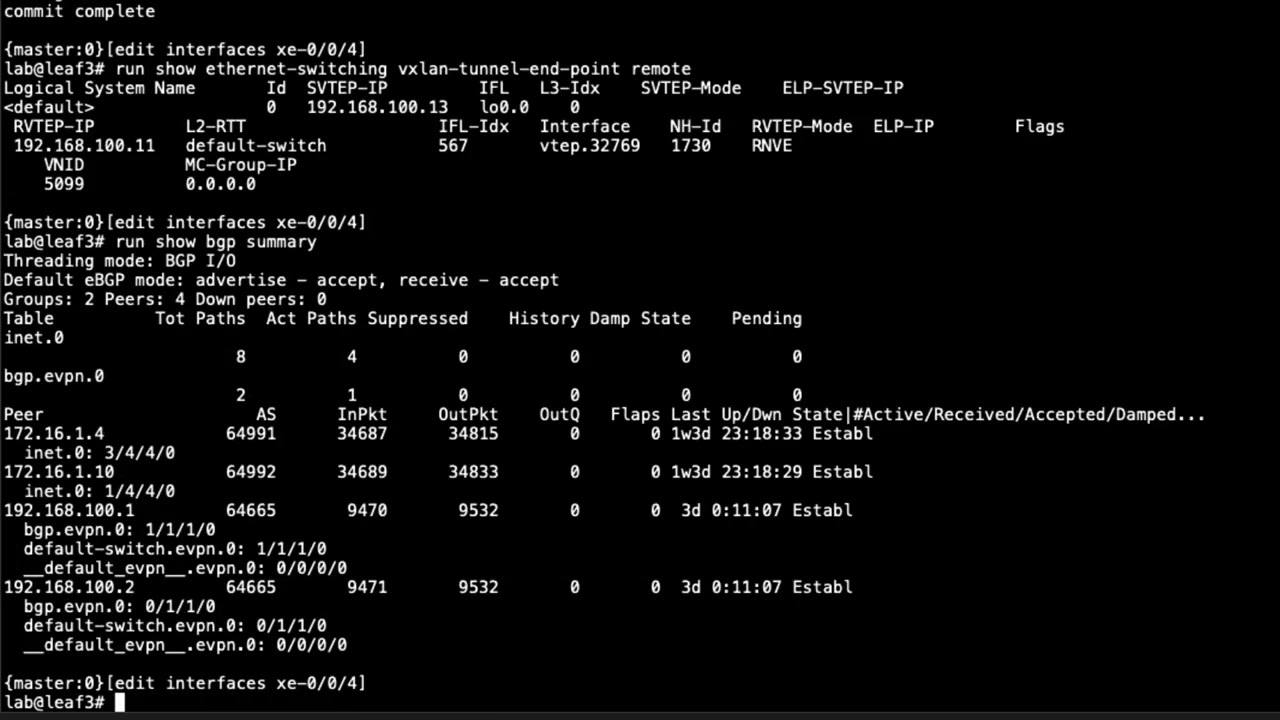
3:46 router l2 you can see that the vni is
3:48 5992 here
3:50 on service leaf l1 with the secure vrf
3:53 secure vrf on router l2 that's the
3:56 router leaf l2 also has the same dni and
3:59 they have matching route targets not
4:01 shown on the slide but there has to be
4:03 matching route targets there so that
4:04 gets forwarded to there
4:06 and then from there there's a route
4:08 inside that secure vrf and i'll show
4:10 this stuff as we go through the learning
4:12 byte as well so don't think that there's
4:13 just way too much to figure out here
4:15 just right here you know you don't have
4:16 to learn it all right here we'll go
4:18 through it all and then in vrf1 it gets
4:21 forwarded to vr4 on that traffic and
4:23 then reaches host 2. and then the return
4:25 traffic is basically going to follow the
4:27 reverse path there so that's how that
4:29 works okay so what do we want to do we
4:32 want to permit ssh traffic
4:34 going from host one host two and then we
4:36 want to block and log any icmp traffic
4:38 that's going from host one to host2 so
4:40 we'll have to set that up in the
4:41 firewall
4:42 and uh yeah we talked about erb being in
4:44 use we need to configure filter-based
4:46 forwarding on the router leafs the
4:48 service leaf and we'll have to do some
4:50 configuration on the firewall mainly the
4:52 security policies i'm not going to
4:54 go through the firewall configuration as
4:56 far as the zones and whatnot because
4:58 that's not really specific to
5:00 filter-based forwarding but we'll still
5:01 take a look at things there all right so
5:03 with that let's go ahead and configure
5:05 the router leaf now this learning byte
5:06 will have a few major sections we'll
5:08 configure the router leafs and then the
5:10 service leaf and then we'll look at the
5:11 firewall and then we'll do some
5:12 verification so
5:14 we'll see that as we go so with that
5:16 let's go ahead and jump to leaf router
5:18 l1 and get this going
5:20 all right so here is the cli of leaf
5:23 router l1 and one thing i want to point
5:26 out is that we will be jumping back to
5:28 the topology because this is a lot to
5:30 try to do
5:31 and try to explain without jumping back
5:34 to the topology and so keep that in mind
5:36 as we're doing this i'm just going to
5:37 jump back and forth as we go so with
5:39 that
5:40 let's go ahead and jump back to the
5:41 topology
5:43 and here is our topology so we are
5:45 configuring router l1 and that means
5:48 we'll need to configure inspect vrf and
5:50 we won't be configuring vrf1 that's
5:52 already configured because that's part
5:54 of the erb architecture so let's go
5:56 ahead and jump back to
5:58 router l1
6:00 and remember this is a router leaf hence
6:02 why it's called router l1 and we want to
6:04 jump to the inspect vrf that's going to
6:06 be a routing instance
6:10 this has not been configured yet and
6:12 before i show that let's look at the
6:14 current vrf1 you can see that's already
6:16 configured notice how the route target
6:18 is
6:19 target colon one two three coin one that
6:21 matches on router l2 that leaf on the
6:24 other side that host two connects to
6:26 that matches there that's very important
6:28 that that matches and that's just basic
6:30 erb so keep that in mind that's not
6:31 really part of filter-based forwarding
6:33 however it is part of erb okay so with
6:36 that let's go ahead and configure the
6:38 instance type we need to set that to
6:40 vrf
6:42 and then we
6:44 don't necessarily need to but it's good
6:46 practice to put a loopback interface in
6:48 here and this loopback interface isn't
6:50 configured yet so we'll need to
6:52 configure that later
6:53 and then we set the route distinguisher
6:56 and let's go ahead and set that to
6:58 this ip well
7:01 it's going to be based off of the ip
7:03 address the loopback address
7:05 but we do need to make it unique
7:08 and we're just naming this what you see
7:10 here with the colon 5991
7:13 and so just
7:15 with the with the other device or with
7:17 the service leaf that is a part of the
7:19 inspector vrf we won't
7:22 you know it'll be unique on that side
7:24 with the route distinguisher itself all
7:25 right so
7:27 with that we need to set the uh the
7:28 route target so we'll use vrf target
7:31 and we'll say
7:33 target
7:35 65601 0 0 1 991
7:39 and this is going to need to match with
7:42 the service leaf
7:43 because these two routing instances
7:45 these two vrs will need to connect
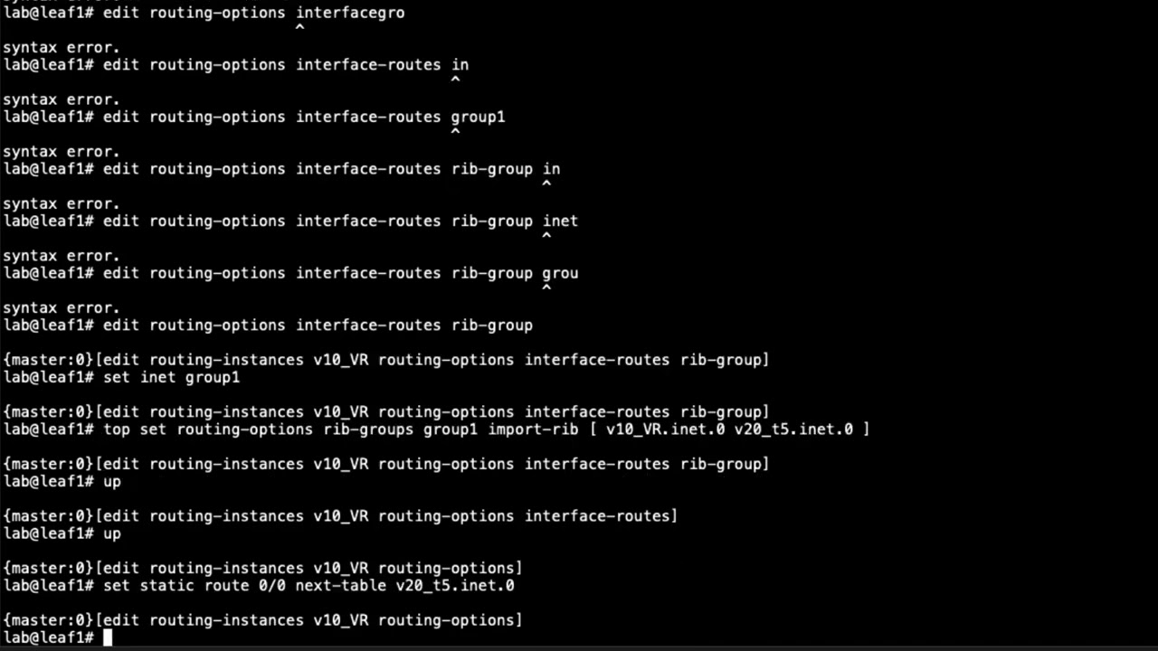
7:47 together all right then we need to
7:49 create a static route
7:53 that points towards host one
7:58 and we need to say next table we need to
8:00 specify
8:02 vrf-1.inet.0 and what this does there's
8:04 really two parts of it what it does it
8:06 allows the return traffic coming back
8:08 that is for host one so the return
8:10 traffic is gonna be from host two to
8:11 host one uh when host one initiates from
8:14 host one to host two and so the return
8:16 traffic when it hits this vrf it'll know
8:18 how to get back to the vr1 vrf
8:22 and then the other part of it is we're
8:23 going to use an export policy to export
8:26 this into the evpn as a type 5 route
8:28 and so then host 2 knows how to get back
8:31 to it as well and also the firewall and
8:33 whatnot so this is very very important
8:35 all right and so with that let's uh set
8:37 up the
8:38 uh set up the the leaf here to advertise
8:41 the ip routes into the uh evpm so we
8:44 need to say protocols set protocols evpn
8:48 iprefix routes
8:50 advertise direct next top we want to
8:53 specify direct next stop we can we don't
8:55 have to do that but we have to do some
8:56 other things this is a nice quick easy
8:57 way to do it so it uses the direct next
9:00 hop
9:01 and then we have the encapsulation vxlan
9:05 now we need to set the vni this is
9:08 important it's gonna be five
9:10 nine nine one
9:11 and you might realize this kind of
9:13 matches the uh the route distinguisher
9:16 that we set up that's not absolutely
9:18 necessary but
9:19 it kind of makes it nice to track things
9:20 down that way so i like to do that
9:23 and then we need to set an export policy
9:25 what are we going to export into the
9:27 evpn as type fibre routes so set
9:31 uh export
9:33 and we need to specify a policy now this
9:34 policy has not been created yet
9:38 so we'll need to create this policy as
9:39 well
9:44 and so we need to configure the
9:46 interface the the loopback interface as
9:48 well as that policy
9:50 and so let's go ahead and create that
9:52 loopback interface right now
10:00 and again this isn't strictly necessary
10:02 it just kind of makes it nice so you can
10:04 see where the routes are coming from and
10:05 make sure stuff is getting passed
10:06 correctly
10:08 and then after that we need to configure
10:10 the
10:11 the export policy that we just created
10:13 there or applied there rather we need to
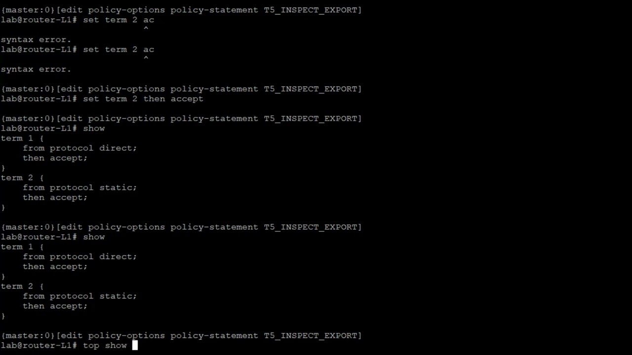
10:16 create it so let's go to policy options
10:18 policy statement t5 underscore inspect
10:23 underscore export so this is the export
10:25 policy for that inspect brf that's where
10:27 that's coming from
10:29 and then we need to
10:31 need to set one term
10:33 from protocol
10:35 direct we want to accept that
10:40 and set a second term
10:41 that is from
10:43 protocol
10:44 static and accept that and so that's
10:47 going to
10:48 that's going to grab that
10:51 loopback interface or the address
10:53 associated with the loopback interface
10:54 and also that static route and we're
10:56 going to advertise that towards the
10:58 service leaf
11:00 and recall we haven't configured the
11:02 service leaf yet so we'll still need to
11:04 do that okay so now that we've done that
11:07 here we can look at the routing instance
11:08 again
11:10 we can see that okay we don't have any
11:12 warnings this time like what we had
11:13 before we have everything configured
11:16 and now we need to configure the
11:18 firewall filter so let's go ahead and
11:21 jump because this is going to be what we
11:22 use to send the traffic into the filter
11:25 base for the traffic towards
11:27 the inspect vrf
11:30 so let's go ahead and
11:33 create a filter we'll just call this
11:35 inspect
11:37 traffic
11:39 and we need to set some terms here term
11:41 one
11:42 uh actually let's call this host
11:44 one
11:46 two host two
11:48 and we're gonna say from source address
11:50 and this is gonna be host one source
11:51 address
11:53 and then destination address and host
11:56 two's destination address
11:59 and then we need to say then
12:01 we're gonna specify the routing instance
12:03 and it's gonna be our inspect vrf
12:04 routing instance and then
12:06 i like to count the traffic here it's
12:08 not necessary but it is nice to set up a
12:10 counter so you know if it's actually
12:12 hitting that firewall filter term and
12:14 being sent towards the routing instance
12:16 very helpful for verification
12:18 troubleshooting and then if we look at
12:19 this we need to add a second term if we
12:21 don't then all the all other traffic
12:23 will get blocked because firewalls have
12:25 an implicit deny so let's go ahead and
12:27 say set term
12:28 i'll say rest
12:31 traffic
12:32 then accept so we want to accept all
12:34 other traffic
12:35 and so things look good there and so
12:37 what we need to do next is we need to
12:40 jump to the layer 3 interface now if we
12:43 go to the routing instance brf1 you can
12:46 see in here that we have two irb
12:49 interfaces irb10 and irb irb20 we need
12:52 to apply this firewall filter to one of
12:54 those interfaces
12:56 so let's go to the irb interface and
12:58 have a look here all right so here you
12:59 can see we have unit 10 and unit 20. and
13:03 so you might ask yourself well what do
13:04 we want to apply this to well recall
13:07 that post one the ip address is 10.1.1.1
13:12 24 which is
13:14 part of unit 10. unit 20
13:18 is 10.1.2.101 10.1.2.101.24
13:20 and they have a virtual gateway address
13:22 as well within that same subnet
13:24 and so that would be what host 2 is part
13:26 of now that is done this way because erb
13:29 is set up so the layer 3 gateways are
13:31 here on the leaf devices and so it's set
13:35 up this way for that reason and so what
13:37 you want to use unit 10.
13:40 apply that filter as an input filter
13:44 and that is the configuration for leaf
13:46 one let's go ahead and commit that
13:48 configuration
13:49 or router l1 which is the leaf connected
13:52 to the host one device
13:55 okay so now that we have that device
13:58 configured router l1 let's configure
13:59 router l2 but let's jump back to the
14:02 topology and have another look at the
14:03 topology to make sure we know what we're
14:06 doing so let's go ahead and jump back
14:08 there
14:08 okay so here is the topology and you can
14:10 see host 2
14:12 is connected to router l2 so that's a
14:14 leaf device in our data center and
14:16 recall we are using erb so edge routed
14:19 bridging
14:20 and so the layer 3 layer 2 gateways are
14:22 on the router leaf devices and so what
14:26 we did previously is we configured
14:28 router l1 that leaf device we configured
14:31 the inspect vrf
14:32 and so what we need to do now is and we
14:35 also configured the filter-based
14:36 forwarding with the firewall filter
14:38 and so what we need to do now is we need
14:40 to configure the secure vrf on router l2
14:44 and what happens there is it's going to
14:46 be very similar to the inspect vrf one
14:48 big difference here is notice how we use
14:50 vni 5991 we're using vni5992
14:53 that's going to match up with the secure
14:55 vrf service leaf l1 uh vni here and same
14:59 thing over here vni 5991 vni 5991 with
15:03 the inspect vrs so that's that's
15:05 important those need to match and also
15:07 the route targets need to match for the
15:08 inspect vrs and as well as a different
15:11 route target needs to match for the
15:12 secure vrs and so here with router l2
15:16 that leaf that router leaf we are going
15:18 to be configuring the secure brf now
15:20 this is erb vf1 is already configured
15:23 but we'll still take a look at things
15:24 there and again host two is in a
15:26 different subnet different vlan than
15:29 host one just something i want to point
15:31 out and so with what we're going to
15:32 focus on right now is the configuration
15:34 of
15:35 router leaf router l2
15:38 so let's go ahead and jump to the cli of
15:41 router l2 and get this going
15:44 all right so here is router l2 and let's
15:47 jump into configuration mode let's go to
15:48 the routing instances hierarchy and have
15:51 a look here and you can see we have vrf1
15:53 you see the route distinguisher the
15:55 interfaces interface type vrf
15:57 the vrf route target that is the route
16:00 target is target colon 123 coin one and
16:04 recall that vrf1 on router l2 so that
16:08 leaf on the other side that is connected
16:10 to host one
16:11 also uses that exact same route target
16:13 for the vrf that's very important those
16:15 two need to match they are part of the
16:17 same vrf
16:18 and so with that let's configure the
16:20 secure
16:22 secure vrf routing instance set the
16:24 instance type
16:26 as
16:27 vrf
16:29 and then set the interface
16:31 loopback interface 992. now again just
16:33 like with router l2 leaf
16:36 it's not necessary but it is helpful for
16:38 tracking purposes that we're setting
16:40 around the loopback interface into the
16:42 evpn as a type 5 route and so we'll need
16:45 to set the route distinguisher
16:47 and we're going to set that
16:51 based off of just the loopback address
16:53 and then specify
16:56 after the colon it's going to be based
16:57 off of the vni
16:59 and then we need to set the route target
17:03 set that to target
17:05 6501 colon 992. now if you remember with
17:10 the leaf router l1 that router leaf we
17:13 used a similar route target but that
17:16 route target was target 65001 colon 991
17:21 and so it doesn't match here because it
17:23 shouldn't match we don't want it to
17:24 match here it will match with a secure
17:26 vrf that is on the service leaf and so
17:30 with that you see here we haven't
17:32 created the loopback interface yet so
17:34 let's go ahead and set that
17:41 and so that is set we don't have that
17:43 warning anymore and then we need to
17:44 create a static route
17:52 and this is for host 2
17:54 we say next table
17:57 brf.1.inet.0.
18:00 and if you remember with configuring the
18:02 leaf router-l1
18:05 we did that for host one because on that
18:08 leaf host one need to be reachable
18:11 through the inspect vrf and that was for
18:13 the return traffic for r2 to be able to
18:15 get to host one from the inspect vrf and
18:19 here it's something very similar just
18:20 the reverse we are setting the static
18:22 route here so host one
18:24 the initiating traffic from a host one
18:27 can get to host two through the secure
18:30 vrf and so we will be exporting this
18:32 static route into the evpn as a type
18:34 five route and so with that let's go
18:37 ahead and configure the type five route
18:40 parameters
18:41 and so let's say protocols evpn ip
18:44 prefix routes advertise direct next hop
18:47 encapsulation vxlan
18:50 set the vni this is going to be 5992 for
18:53 the vni
18:54 and then we need to accept the export
18:56 policy this is going to be t5
18:59 underscore export
19:01 actually let's do secure
19:04 underscore export
19:07 and that hasn't been configured yet so
19:08 let's go ahead and configure that policy
19:11 and so policy options policy statement
19:14 t5
19:17 here
19:18 x
19:20 port
19:21 term one this is going to look very
19:22 familiar to what we did on router leaf
19:25 router l1
19:27 and so with that we'll say set
19:30 from protocol
19:32 direct
19:34 set
19:35 then accept
19:36 and we're going to configure a second
19:38 term that's from
19:40 protocol static
19:42 then accept
19:45 and so if we jump back to the routing
19:46 instance
19:48 we can see here that we have configured
19:51 that export policy it's not giving us a
19:52 warning now so that'll export
19:55 the static route we have configured and
19:57 the route associated with the loopback
19:59 unit 992 interface
20:02 and so the next step would be to
20:04 configure the firewall filter
20:06 and again we have the vrf1 routing
20:08 instance and we have the two interfaces
20:10 rb10 and irb20
20:13 and so we need to figure out which
20:15 interface we need to apply it to
20:17 the firewall filter that is and if you
20:20 look at here
20:21 you can see that host 1 is in the subnet
20:24 of irb.10 host 2 is in the subnet of
20:28 irb.20. so we're going to apply that
20:30 firewall filter there
20:31 on unit 20. but before we apply it we
20:34 need to create it so let's go ahead and
20:36 create that firewall filter should have
20:37 done that first
20:47 call the term host two to host one since
20:51 it'll be the return direction set the
20:53 host address we'll set it to match on
20:57 the host to source address
21:02 and then the host one destination
21:04 address
21:09 say routing instance secure so this is
21:11 going to be going to the secure vrf
21:12 because the traffic this traffic at this
21:15 point will already be inspected and
21:17 analyzed by the firewall
21:19 and then we need to
21:21 set a counter again strictly not
21:24 necessary but it's really helpful for
21:26 troubleshooting purposes and
21:28 verification and then again we want to
21:31 set a catch-all term
21:34 for any other traffic
21:39 and then let's jump back to the irb
21:41 interfaces
21:43 recall it's unit 20 we want to use here
21:45 for the input filter
21:51 and that is the configuration for the
21:53 router leaf router l2
21:56 alright so that brings us to the end of
21:58 this learning byte
22:00 we demonstrated how to configure router
22:02 leafs with regards to data center filter
22:04 based forwarding so as always thanks for
22:07 watching
22:09 visit the juniper education services
22:12 website to learn more about courses
22:15 view our full range of classroom online
22:18 and e-learning courses
22:20 learning paths
22:22 industry segment and technology specific
22:24 training paths juniper networks
22:27 certification program the ultimate
22:29 demonstration of your competence and the
22:32 training community from forums to social
22:35 media join the discussion
22:43 you