ON THIS PAGE
High Availability Design for WAN Edge Devices
Use this design guide to configure high availability for your WAN Edge devices in Juniper Mist WAN Assurance.
The High Availability (HA) design for WAN Edge devices is for administrators who want to ensure that interfaces or whole devices can take over for one another in the event of a failure in their WAN Edge deployments. This is for administrators who want to deploy HA WAN Edge devices at the Edge, but not for Whitebox setups.
In this documentation, you’ll find step-by-step guidance for setting up an HA hub and spoke deployment using Juniper® Mist WAN Assurance. This builds upon the hub and spoke topology referenced in this guide. After you've configured that topology, use the steps below to set up WAN Edge devices for HA.
If you need to set up your hub and spoke topology, see Configure a WAN Edge Template and Configure Path Selection from Hub-to-Spoke with Traffic Steering, then return to this procedure.
The device hardware used in an HA pair must be identical. For example, an HA pair with two SSR120 Routers is compatible for HA, whereas an HA pair with one SSR120 and one SSR130 is incompatible.
Overview
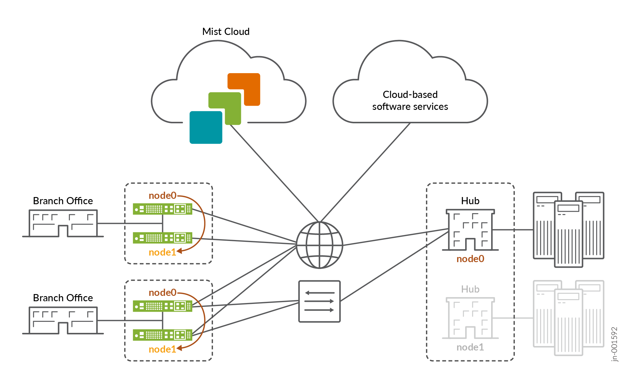
You will deploy a highly available Hub and Spoke as shown in Figure 1. In the figure below, we see the Juniper Mist WAN Assurance High Availability topology. Nodes of an HA pair can be configured to run as active/standby or active/active. You can also set up your hubs for HA if needed.
Interfaces
The Interfaces use the following pattern for each node:
Node0: ge-0/0/x
Node1: ge-1/0/x
For SRX devices, follow the naming pattern found in SRX Cluster Slot Numbering and Logical Interface Naming.
For SSR devices, follow the naming pattern found in SSR Device Default Port Layout.
WAN Interfaces for HA hubs require static IP addresses. Spokes reach out across the overlay to these WAN interface endpoints.
WAN Interfaces for HA
Each path and Node in an HA network require their own designated WAN interface. This ensures active/active usage, meaning that these interfaces stay active and engaged, no matter what. WAN interfaces on spoke devices can contain either a static IP address or be linked to a DHCP-lease, giving you flexibility in how you manage them.
LAN Interfaces for HA
You’ll need to define the LAN interfaces for both HA hubs and spokes as redundant interfaces, and then specify the interfaces together as ge-0/0/x, ge-1/0/x.
Redundant Interfaces are only Active/Passive, meaning the active WAN Edge device will ARP for the IP address configured on the interface.
The redundant interfaces must be in the same Layer 2 domain and need a single static IP address for Session Smart Routers (SSRs). These interfaces will have a shared MAC address. Based on the device, the system decides who will be node0 and who will be node1. SRX Series Firewalls do not need the same layer 2 domain for redundant interfaces.
- The lowest MAC address will be selected for node0.
- For redundant interfaces, you can define which node is the primary, but we recommend leaving the default to node0 for consistency.
Prerequisites for High Availability
-
Onboarded your WAN Edge device to the Mist cloud. If you need to onboard a WAN Edge device, follow the steps in Cloud Ready SSR Devices Quick Start Guide or Cloud Ready SRX Series Firewalls Quick Start Guide.
-
Created a site, which you will assign your WAN Edge template to later in this HA workflow. If you need to create a new site, see the Juniper Mist Management Guide.
-
Configured Networks, Applications, Variables, Hub Profiles and WAN Edge Templates.
-
If any of these steps are new to you, follow the applicable links in WAN Assurance Configuration Overview before returning to this procedure.
Note: Both devices in an HA pair must be on the same firmware version.
-
Connect HA Synchronization and Fabric Links
It's important to be aware of the two specific Ethernet interfaces that handle HA synchronization and fabric data exchange on the supported devices.
The HA synchronization link ensures that the two devices are chronologically synchronized and can swap appropriately in the event of an interface or device failure. The synchronization interface serves as the back-or-midplane of a chassis-based router.
The fabric interface is a forwarding interface between two nodes in a router and is used for forwarding data when the ingress interface and egress interface for a given session are active on different nodes.
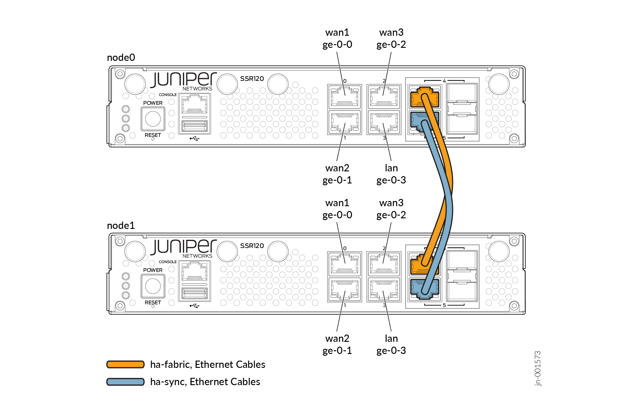
The synchronization and fabric interfaces are usually the two last ports of the system. You must wire them back-to-back with direct patch cables, as these are physical connections between the two nodes that are collocated in the same datacenter. See Figure 2 below.
To have a functional HA cluster, you must connect dedicated ports for the ha sync and fabric interfaces. To understand which ports to use for these, see SRX Cluster Slot Numbering and Logical Interface Naming and SSR Device Default Port Layout.
Configure Nodes for Redundancy
To do this, you must either edit an existing WAN Edge template and update it with the appropriate node interface configuration, or you can Create a new template with the necessary node interface configuration. This procedure demonstrates how to configure a template for HA.
-
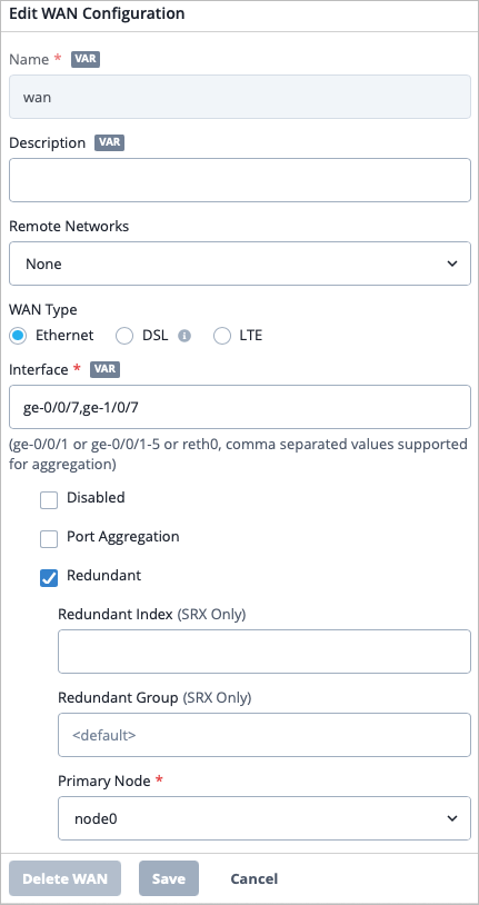
Select the Redundant checkbox. If you are
configuring HA for SSRs, skip ahead to step 5.
Customize the Fabric Interface if needed
- Login to the Mist portal.
- Click the ? button in the top right corner, then click API Documentation.
- From the Site section of the table of contents, click the HA Cluster link. Use the documentation to learn how to customize the fabric link of your HA cluster in the API. The documentation demonstrates using the SRX, but is applicable to any type of WAN Edge device.
- Navigate to the API URL for your global region to customize the fabric interface according to the instructions. See API Endpoints and Global Regions .
- If you need to learn more about how to use the API, see Use the Django Web Interface to Make API Changes , Additional RESTful API Documentation, and the Juniper Mist API Reference.
Assign the Template to a Site
Assign the HA Devices to a Site and Create an HA Cluster
WAN Edge devices can be configured to operate as an HA cluster. An HA cluster is where a pair of devices can be connected together and configured to operate as a single device to provide high availability. You may want to cluster an existing WAN Edge device with a brand new WAN Edge device for the purpose of high availability. With Mist, you can cluster WAN Edge devices automatically.
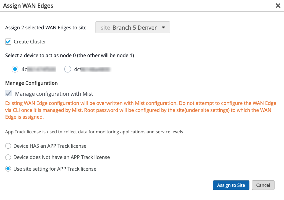
-
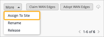
Click the More button in the top right corner of the
page, then select Assign To Site. You will only be
able to assign a site to two devices at the same time when those devices are
the same hardware model.
-
Select the Create Cluster checkbox. Once that
checkbox is selected, the Manage configuration with
Mist option is automatically selected.
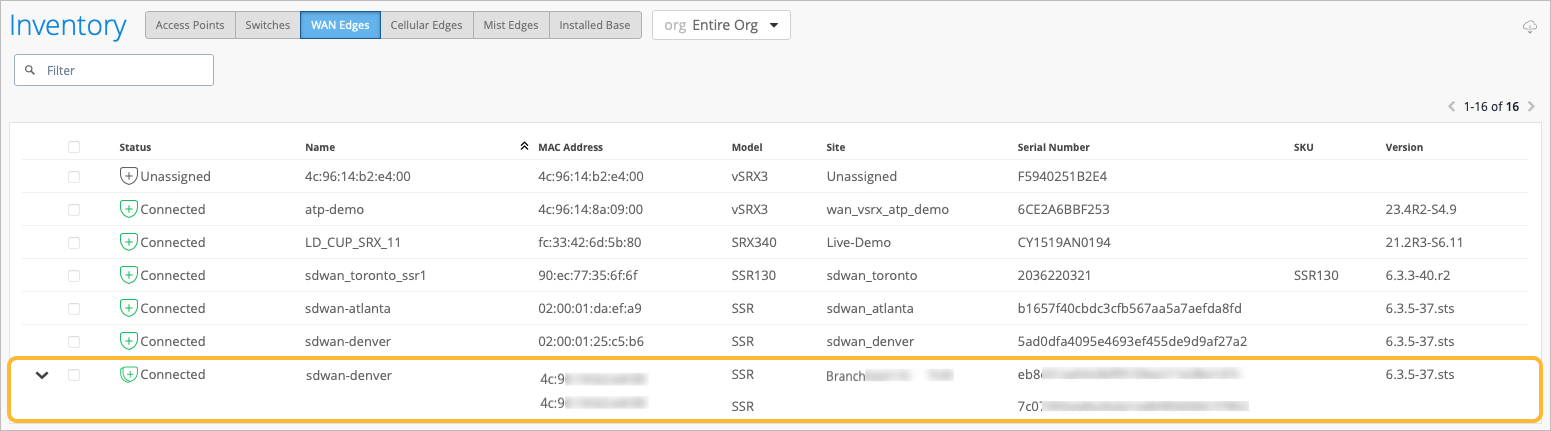
-
Verify that your devices have been clustered. A double graphic to the left
of the device in the Inventory list indicates that the devices have
successfully been clustered. You can also expand the row to see the MAC
addresses for the two devices.
Configure Traffic Steering Rules
Traffic steering rules direct the flow of data traffic from one location or device to another. These rules help control how data packets are routed within a network, ensuring efficient and optimized data delivery.
To learn more about Traffic Steering, see Traffic Steering Rules and Configure Path Selection from Hub-to-Spoke with Traffic Steering.
Table 1 below provides a sample configuration of one traffic steering rule. One rule can contain multiple paths, allowing you to specify which path you want as the primary path for traffic to take when reaching an application, and a secondary path that traffic can take if the first path goes down. Once you create an application policy and apply the traffic steering rule to it, traffic will follow that rule when attempting to access the application.
| Name | Overlay |
|---|---|
| Strategy | ECMP |
| Paths | h1-wan0, h1-wan1 |
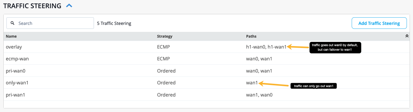
In Figure 3 below, there are multiple traffic steering rules configured. The primary path traffic will take is the first path listed, and the second path listed is the secondary path that traffic can failover to if needed (from left to right).
Configure Application Policies
You will now modify the application policies in your WAN Edge template to define which networks and users can access which applications, and which traffic steering policies are used. For more information on how to create a new application policy, see Application Policies.
Table 2 provides a sample configuration of one application policy.
| Field | How to Configure |
|---|---|
| Name | guest-internet |
| Network | spoke-guest |
| Action | Allow |
| Application/Destination | any |
| Traffic Steering | only-wan1 |
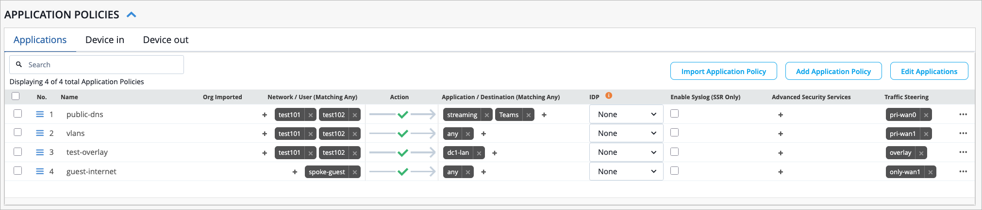
In Figure 4, the application policies are configured with the traffic steering rules from Figure 3. In the "public-dns" application policy, traffic will use wan0 as the primary path and wan1 as the backup path as defined by the "pri-wan0" traffic steering rule. The "guest-internet" application policy states that traffic can only take the wan1 path.
Configure a High Availability Cluster (Video Walkthrough)
In this video, we will demonstrate how SRX series devices can be configured to operate in cluster mode. Cluster mode is where a pair of devices can be connected together and configured to operate as a single device in order to provide high availability. With MIST, we are able to cluster our SRX devices and SSR devices automatically.
At this point, we are already logged into the MIST portal and we are currently looking at the WAN edges page. Two devices have already been onboarded using zero-touch provisioning. During that process, the boxes are connected to the network and are powered on.
They phone home automatically to the MIST cloud and they onboard themselves. By looking at the site column, we can see that no sites have been assigned to our SRX300s. We can assign sites to both of these devices at the same time because both devices are of the same model.
Once the devices have been selected, the More button will appear in the top right corner of the screen. We'll click the More button and then we'll click the Assign to Site option. In the Assign WAN Edges window, we'll click the dropdown to select a site to assign to the selected devices.
Note, the action of putting the device into a site is what builds the cluster. We will discuss the role that sites play in SRX clustering later in this video. Notice the Create Cluster option.
Note, the Create Cluster option will not be available if the user has selected a single device or if the selected devices are not matching models. Once the Create Cluster option has been selected, notice that the Manage Configuration with Mist option is automatically selected in grayed out. This means that when we create the cluster, it will be Mist managed.
Now we'll click on the Assign to Site button to save the changes. We can see that the two devices have been assigned a new site. Now we'll click Close to close the window.
At this point, on the SRX platform, the box needs to be rebooted from standalone mode to cluster mode. This is normally a manual process that the user would have to go through. With MIST, however, this process has been automated.
MIST will run the correct commands on each box individually to build them into a cluster. Note, this process can take up to 15 minutes to complete. At this point, the device is connected to the MIST cloud.
We can see that the device has a double graphic next to it, indicating that the two devices have been clustered. Now we'll click on the arrow to the left of the row to expand more information. The box is connected, and we can see both serial numbers listed in the Serial Number column, which is another indication that the two devices have been clustered successfully.
To see more detailed information on the clustered devices, we can click on the row. We are now brought to the WAN Edges page. At the top of the page, we see both nodes listed.
MIST will automatically assign the lower MAC address to node 0, or the primary node, and the higher MAC address to node 1, or the secondary node. We can also use the Secondary and Primary buttons at the top left of the page to see information about the individual nodes. In the top right section of the page, we can click on either of the fabric interfaces.
This will draw a line between the two interfaces, indicating their connection. Scrolling down on the page, in the Properties section, we can see that there is a template bound to the site. A full configuration was delivered to the device because of the template that is bound.
It is important to note that the action of putting the device into a site is what builds the cluster. We will click on the template now to see more information. Notice that within a template, once we click on the interface name, in this case WAN0, we have the ability to configure the elements that we want to be configured on the device.
For example, we can enter the names of the interfaces that we want to be redundant, and we can indicate that the nodes are redundant. Navigating back to the WAN Edges page, we see the WAN Edge Insights link. Clicking on this link will bring us to the Insights page, where we can gather details about what is going on with the device.
For example, we see events for ConfigChangedByUser and WAN Edge Connected. From the list of events, we can see that the configuration was delivered to the device. Therefore, we know that this is now a working node within our SD-WAN environment.
At the bottom of the page, we can see that tunnels were built and BGP was stood up for our cluster. That concludes this video on how to create an SRX cluster. I hope you enjoyed.
Have a good day.