Slot Numbering and Logical Interface Naming
This topic explains the slot numbering, physical port naming, and logical interface naming conventions for Firewalls operating in a chassis cluster.
Use Feature Explorer to confirm platform and release support for specific features.
Review the Platform-Specific Chassis Cluster Slot Numbering Behavior section for notes related to your platform.
In chassis cluster mode, the interfaces on the firewall operating as node 1 are internally renumbered.
After the devices are connected to form a cluster, the slot numbering on the firewall acting as node 1 changes, and as a result, the interface numbering also changes. For more information, see Interfaces User Guide for Security Devices for detailed interface naming conventions.
The slot number for each slot on both nodes is calculated using the following formula:
cluster slot number = (node ID * maximum slots per node) + local slot number
Chassis Cluster Slot Numbering and Physical Port and Logical Interface Naming
Table 1 shows the slot numbering, and the physical port and logical interface numbering, for both the Firewalls after they are formed into a chassis cluster as node 0 and node 1.
|
Model |
Chassis |
Maximum Slots Per Node |
Slot Numbering in a Cluster |
Management Physical Port/Logical Interface |
Control Physical Port/Logical Interface |
Fabric Physical Port/Logical Interface |
|---|---|---|---|---|---|---|
|
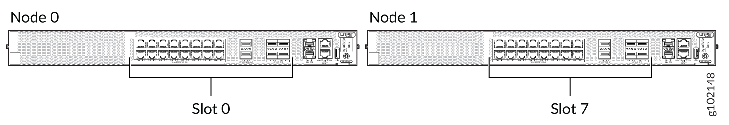
SRX1600 |
Node 0 |
3 |
0 |
fxp0 |
Dedicated dual Control links with MACsec support |
Dual fabric links |
|
em0/em1 |
fab0 |
|||||
|
Node 1 |
7 |
fxp0 |
Dedicated dual Control links with MACsec support |
Dual fabric links |
||
|
em0/em1 |
fab1 |
|||||
|
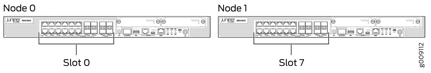
SRX1500 |
Node 0 |
3 |
0 |
fxp0 |
Dedicated Control port |
Any Ethernet port |
|
em0 |
fab0 |
|||||
|
Node 1 |
7 |
fxp0 |
Dedicated Control port |
Any Ethernet port |
||
|
em0 |
fab1 |
|||||
|
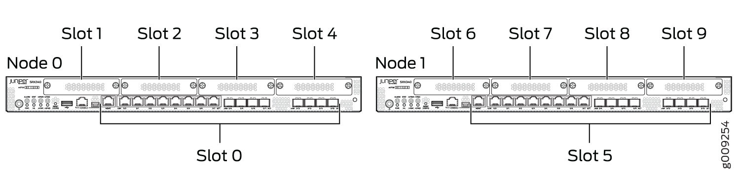
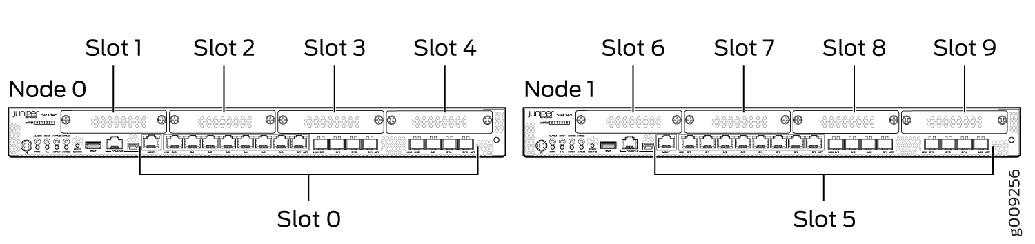
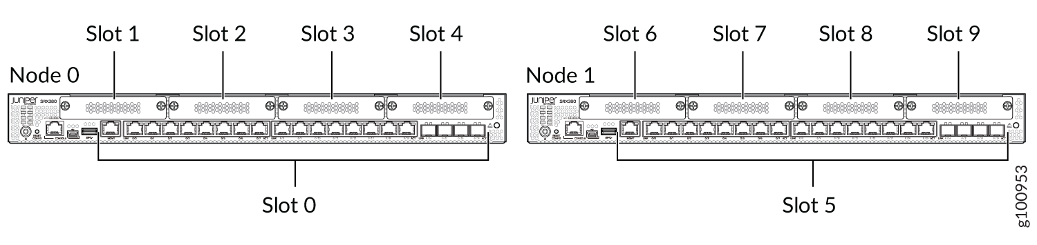
SRX340,SRX345, and SRX380 |
Node 0 |
5 (PIM slots) |
0—4 |
fxp0 |
ge-0/0/1 |
Any Ethernet port |
|
fxp0 |
fxp1 |
fab0 |
||||
|
Node 1 |
5—9 |
fxp0 |
ge-5/0/1 |
Any Ethernet port |
||
|
fxp0 |
fxp1 |
fab1 |
||||
|
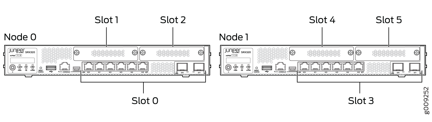
SRX320 |
Node 0 |
3 (PIM slots) |
0—2 |
ge-0/0/0 |
ge-0/0/1 |
Any Ethernet port |
|
fxp0 |
fxp1 |
fab0 |
||||
|
Node 1 |
3—5 |
ge-3/0/0 |
ge-3/0/1 |
Any Ethernet port |
||
|
fxp0 |
fxp1 |
fab1 |
||||
|
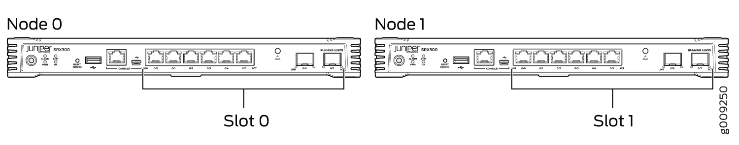
SRX300 |
Node 0 |
1(PIM slot) |
0 |
ge-0/0/0 |
ge-0/0/1 |
Any Ethernet port |
|
fxp0 |
fxp1 |
fab0 |
||||
|
Node 1 |
1 |
ge-1/0/0 |
ge-1/0/1 |
Any Ethernet port |
||
|
fxp0 |
fxp1 |
fab1 |
|
Interfaces |
Used as Fabric Port? |
Supports Z-Mode Traffic? |
Supports MACsec? |
|---|---|---|---|
|
16X1Gigabit Ethernet Interface -BASE-T RJ45 |
Yes |
Yes |
No |
|
2x 25G SFP28 |
Yes |
Yes |
No |
|
4x 10G SFP+ |
Yes |
Yes |
No |
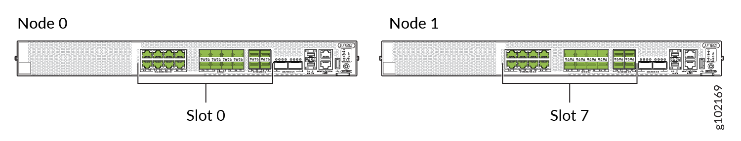
After chassis clustering is enabled, the two joined chassis no longer operate as independent devices and instead function as a single system. As a result, the cluster has twice the number of slots. (See Figure 1, Figure 2, Figure 3, Figure 4, and Figure 6.)
Chassis Cluster Slot Numbering and Physical Port and Logical Interface Naming for SRX4600 Firewalls
Table 3 and Table 4 show the slot numbering, as well as the physical port and logical interface numbering, for both of the Firewalls that become node 0 and node 1 of the chassis cluster after the cluster is formed.
|
Model |
Chassis Cluster |
Maximum Slots Per Node |
Slot Numbering in a Cluster |
Management Physical Port/Logical Interface |
Control Physical Port/Logical Interface |
Fabric Physical Port/Logical Interface |
|---|---|---|---|---|---|---|
|
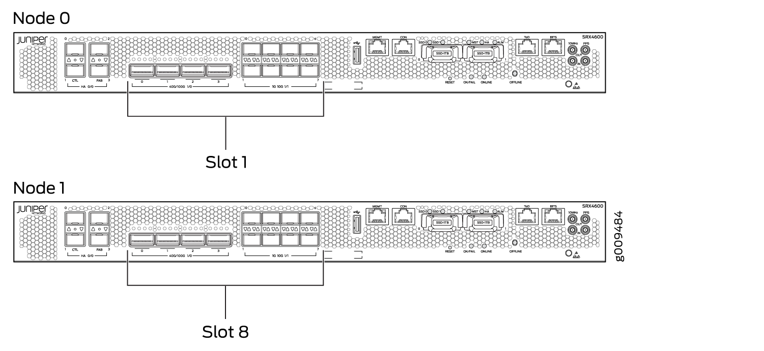
SRX4600 |
Node 0 |
1 |
0-6 |
fxp0 |
Dual (redundant) MACsec-enabled HA control ports (10GbE) are xe-0/0/0, xe-0/0/1, xe-7/0/0, and xe-7/0/1. It uses 1-Gigabit Ethernet SFP as control port. |
Dual (redundant) MACsec-enabled HA fabric ports (10GbE) Dual Fabric ports with macsec enabled are xe-0/0/2 and xe-0/0/3 |
|
Node 1 |
7-13 |
|
Device |
Renumbering Constant |
Node 0 Interface Name |
Node 1 Interface Name |
|---|---|---|---|
|
SRX4600 |
7 |
xe-1/0/0 |
xe-8/0/0 |
|
Interfaces |
Used as Fabric Port? |
Supports Z-Mode Traffic? |
Supports MACsec? |
|---|---|---|---|
|
Dedicated fabric ports |
Yes |
Yes |
Yes |
|
8X10-Gigabit Ethernet Interface SFPP ports |
Yes |
Yes |
No |
|
4X40-Gigabit Ethernet Interface QSFP28 ports |
Yes |
Yes |
No |
|
4x10-Gigabit Ethernet Interface SFPP ports |
Yes |
Yes |
No |
|
2X100-Gigabit Ethernet Interface QSFP28 slots |
No |
No |
No |
Mixing different types of fabric ports is not supported. For example, you cannot configure a fabric link using one 10-Gigabit Ethernet interface and one 40-Gigabit Ethernet interface. Dedicated fabric links support only 10-Gigabit Ethernet interfaces.
Figure 8 shows the slot numbering for both of the Firewalls that become node 0 and node 1 of the chassis cluster after the cluster is formed.
Chassis Cluster Slot Numbering and Physical Port and Logical Interface Naming for SRX2300, SRX4120, SRX4100, SRX4200, and SRX4300 Devices
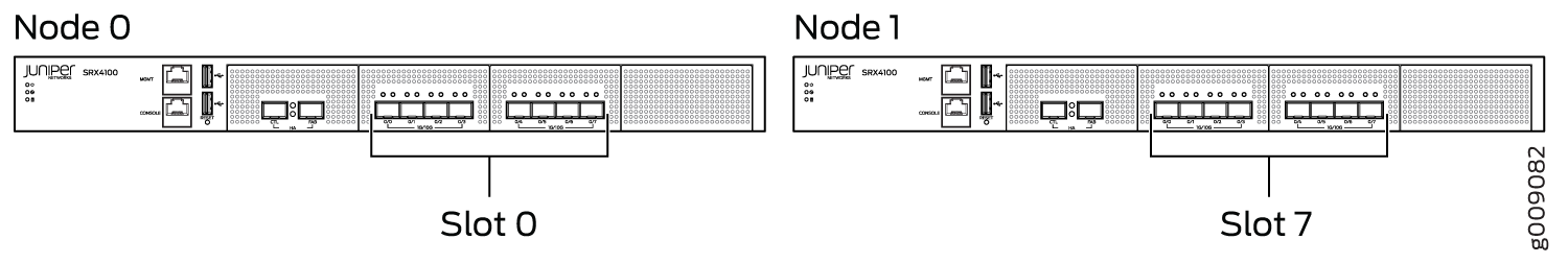
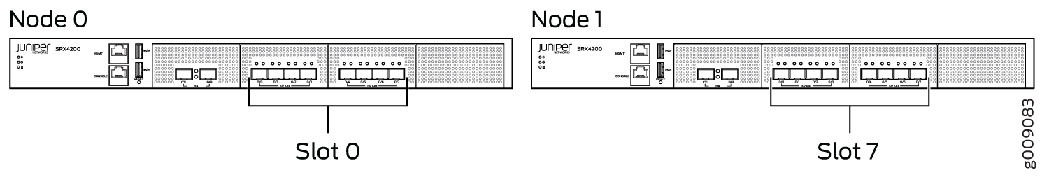
The SRX4100 and SRX4200 devices use two 1-Gigabit Ethernet/10-Gigabit Ethernet ports, labeled as CTL and FAB as control port and fabric port respectively.
The SRX4300 devices supports 1-Gigabit Ethernet labeled as CTL control port.
Supported fabric interface types for SRX4100 and SRX4200 devices are 10-Gigabit Ethernet (xe) (10-Gigabit Ethernet Interface SFP+ slots).
|
Ports with Port Speed |
Used as Fabric Port? |
Supports Z-Mode Traffic? |
Supports MACsec? |
|---|---|---|---|
|
8X 1/2.5/5/10-Gigabit Ethernet Interface SFPP |
Yes |
Yes |
Yes |
|
8x 1/10-Gigabit Ethernet Interface BASE-T RJ45 |
Yes |
Yes |
Yes |
|
4X 1/10/25-Gigabit Ethernet Interface SFP28 |
Yes |
Yes |
Yes |
|
2X 40/100-Gigabit Ethernet Interface QSFP28 |
Yes |
No |
Yes |
|
Ports with Port Speed |
Used as Fabric Port? |
Supports Z-Mode Traffic? |
Supports MACsec? |
|---|---|---|---|
|
8x1/2.5/5/10-Gigabit Ethernet Interface BASE-T RJ45. |
Yes |
Yes |
Yes |
|
8X1/10-Gigabit Ethernet Interface SFPP. |
Yes |
Yes |
Yes |
|
4X1/10/25-Gigabit Ethernet Interface SFP28. |
Yes |
Yes |
Yes |
|
6X 40/100-Gigabit Ethernet Interface QSFP28. |
Yes |
No |
Yes |
|
2X1-Gigabit Ethernet Interface SFP HA. |
No |
No |
Yes |
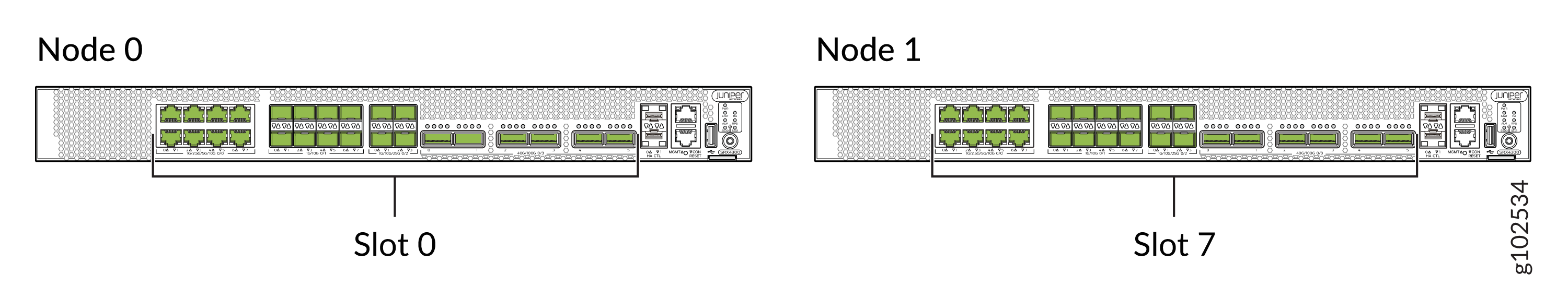
Table 8 shows the slot numbering, as well as the physical port and logical interface numbering, for both of the Firewalls that become node 0 and node 1 of the chassis cluster after the cluster is formed
|
Model |
Chassis Cluster |
Maximum Slots Per Node |
Slot Numbering in a Cluster |
Management Physical Port/Logical Interface |
Control Physical Port/Logical Interface |
Fabric Physical Port/Logical Interface |
|---|---|---|---|---|---|---|
|
SRX2300 and SRX4120 |
Node 0 |
1 |
0 |
fxp0 |
Dedicated control port, em0/em1 |
Revenue interfaces are used for dual fabric links, fab0. |
|
Node 1 |
7 |
Revenue interfaces are used for dual fabric links, fab1. |
||||
|
SRX4100 |
Node 0 |
1 |
0 |
fxp0 |
Dedicated control port, em0 |
Dedicated fabric port, any Ethernet port (for dual fabric-link), fab0 |
|
Node 1 |
7 |
Dedicated fabric port, and any Ethernet port (for dual fabric-link), fab1 |
||||
|
SRX4200 |
Node 0 |
1 |
0 |
fxp0 |
Dedicated control port,em0 |
Dedicated fabric port, and any Ethernet port (for dual fabric-link), fab0 |
|
Node 1 |
7 |
Dedicated fabric port, and any Ethernet port (for dual fabric-link), fab1 |
||||
|
SRX4300 |
Node 0 |
1 |
0 |
fxp0 |
Dedicated control port, em0/em1 |
Revenue interfaces are used for dual fabric links, fab0 |
|
Node 1 |
7 |
Revenue interfaces for dual fabric links, fab1 |
Figure 10 and Figure 11 shows the slot numbering for both of the Firewalls that become node 0 and node 1 of the chassis cluster after the cluster is formed.
The node 1 renumbers its interfaces by adding the total number of system FPCs to the original FPC number of the interface. For example, see Table 9 for interface renumbering on the Firewalls (SRX4100, SRX4200, and SRX4300).
|
Device |
Renumbering Constant |
Node 0 Interface Name |
Node 1 Interface Name |
|---|---|---|---|
|
SRX1600 |
7 |
xe-0/1/0 |
xe-7/1/0 |
|
SRX2300 and SRX4120 |
7 |
xe-0/2/0 |
xe-7/2/0 |
|
SRX4100 |
7 |
xe-0/0/0 |
xe-7/0/0 |
|
SRX4200 |
7 |
xe-0/0/1 |
xe-7/0/1 |
|
SRX4300 |
7 |
xe-0/1/0 |
xe-7/1/0 |
On SRX4100 and SRX4200 devices, when the system boots in chassis cluster mode, the xe-0/0/8 and xe-7/0/8 interfaces are automatically configured as fabric links. You can configure an additional pair of fabric interfaces by using any supported pair of 10-Gigabit Ethernet interfaces to provide fabric connectivity between the nodes.
Note that the automatically created fabric interfaces cannot be deleted. However, the second pair of fabric interfaces that you can configure manually can be removed if needed.
Chassis Cluster Slot Numbering and Physical Port and Logical Interface Naming for SRX5000 Line of Firewalls
For chassis clustering, all Firewalls include a built-in management
interface named fxp0. On most Firewalls, the
fxp0 interface is a dedicated port.
For SRX5000 line of Firewalls, control interfaces are configured on SPCs.
Table 10 shows the slot numbering, as well as the physical port and logical interface numbering, for both of the Firewalls that become node 0 and node 1 of the chassis cluster after the cluster is formed.
|
Model |
Chassis Cluster |
Maximum Slots Per Node |
Slot Numbering in a Cluster |
Management Physical Port/Logical Interface |
Control Physical Port/Logical Interface |
Fabric Physical Port/Logical Interface |
|---|---|---|---|---|---|---|
|
SRX5800 |
Node 0 |
12 (FPC slots) |
0—11 |
Dedicated Gigabit Ethernet port |
Control port on an SPC |
Any Ethernet port |
|
fxp0 |
em0 |
fab0 |
||||
|
Node 1 |
12—23 |
Dedicated Gigabit Ethernet port |
Control port on an SPC |
Any Ethernet port |
||
|
fxp0 |
em0 |
fab1 |
||||
|
SRX5600 |
Node 0 |
6 (FPC slots) |
0—5 |
Dedicated Gigabit Ethernet port |
Control port on an SPC |
Any Ethernet port |
|
fxp0 |
em0 |
fab0 |
||||
|
Node 1 |
6—11 |
Dedicated Gigabit Ethernet port |
Control port on an SPC |
Any Ethernet port |
||
|
fxp0 |
em0 |
fab1 |
||||
|
SRX5400 |
Node 0 |
3 (FPC slots) |
0—2 |
Dedicated Gigabit Ethernet port |
Control port on an SPC |
Any Ethernet port |
|
fxp0 |
em0 |
fab0 |
||||
|
Node 1 |
3—5 |
Dedicated Gigabit Ethernet port |
Control port on an SPC |
Any Ethernet port |
||
|
fxp0 |
em0 |
fab1 |
FPC Slot Numbering in Firewall Cards
SRX5600 and SRX5800 have Flex I/O Cards (Flex IOCs) that have two slots to accept the following port modules:
-
SRX-IOC-4XGE-XFP 4-Port XFP
-
SRX-IOC-16GE-TX 16-Port RJ-45
-
SRX-IOC-16GE-SFP 16-Port SFP
You can use these port modules to add from 4 to 16 Ethernet ports to your Firewall. Port numbering for these modules is:
slot/port module/port
where slot is the number of the slot in the device in which the Flex IOC is installed; port module is 0 for the upper slot in the Flex IOC or 1 for the lower slot when the card is vertical, as in an SRX5800 device; and port is the number of the port on the port module. When the card is horizontal, as in an SRX5400 or SRX5600, port module is 0 for the left-hand slot or 1 for the right-hand slot.
SRX5400 Firewall support only SRX5K-MPC cards. The SRX5K-MPC cards also have two slots to accept the following port modules:
-
SRX-MIC-10XG-SFPP 10-port-SFP+ (xe)
-
SRX-MIC-20GE-SFP 20-port SFP (ge)
-
SRX-MIC-1X100G-CFP 1-port CFP (et)
-
SRX-MIC-2X40G-QSFP 2-port QSFP (et)
Platform-Specific Chassis Cluster Slot Numbering Behavior
Use Feature Explorer to confirm platform and release support for specific features.
Use the following table to review platform-specific behaviors for your platform.
|
Platform |
Difference |
|---|---|
|
SRX Series |
|