
Configure Chassis Cluster
This topic explains on how Firewalls are configured to operate in cluster mode, in which a pair of devices is connected and configured to function as a single system.
Use Feature Explorer to confirm platform and release support for specific features.
Review the Platform-Specific Interface Renumbering Behavior section for notes related to your platform.
See the Additional Platform Information section for more information.
In a chassis cluster configuration, the two nodes back up each other, with one node acting as the primary device and the other as the secondary device, enabling stateful failover of processes and services in the event of a system or hardware failure. If the primary device fails, the secondary device automatically takes over traffic processing.
Chassis cluster settings is not enabled in the factory-default configuration. Before enabling chassis cluster, you must remove any existing configurations from the physical interfaces that will be used for the chassis cluster. See Additional Platform Information section for more information on the physical interfaces.
Example: Configure Chassis Cluster SRX Series Firewalls
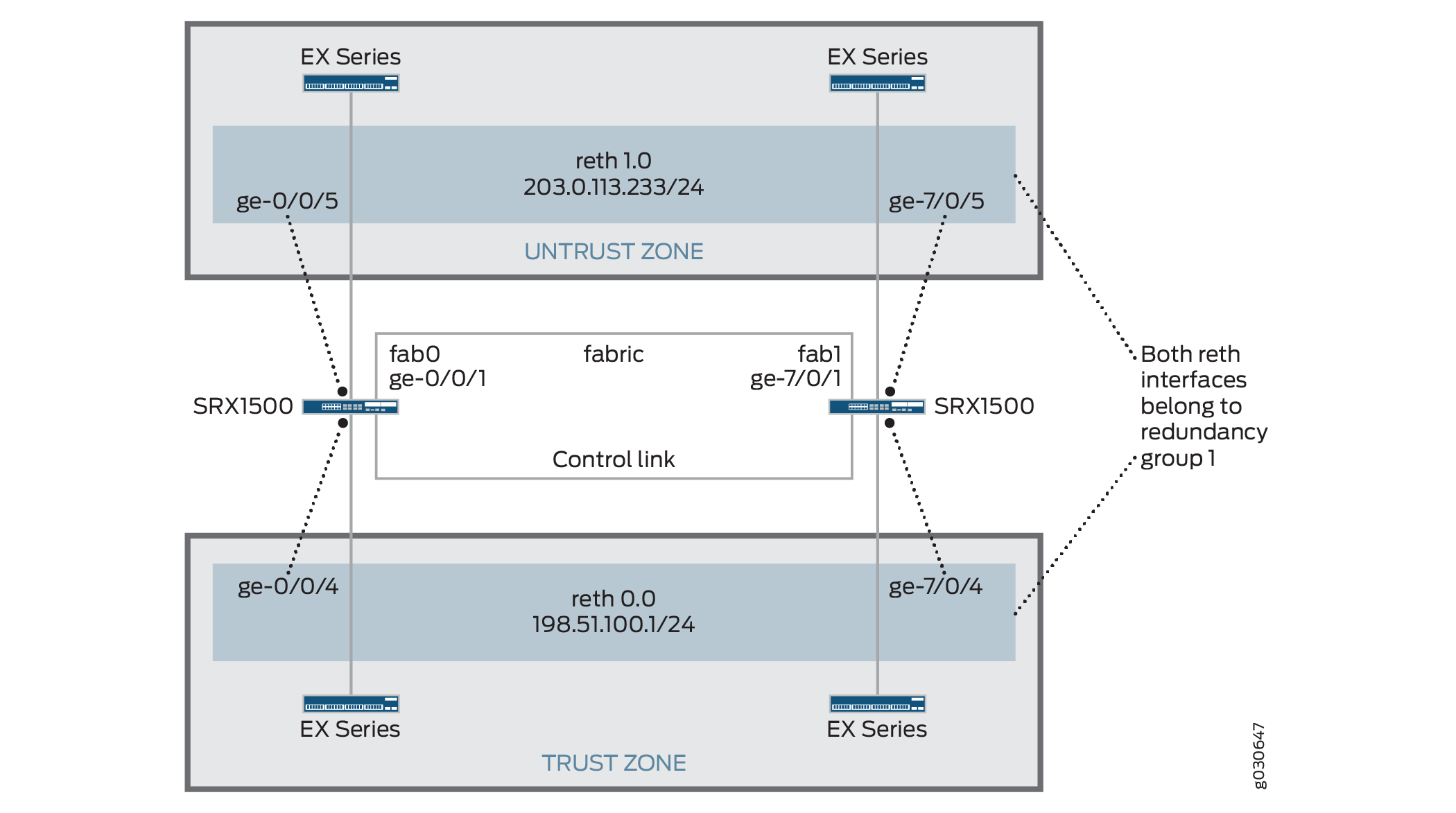
This example shows how to set up chassis clustering on a Firewall, using SRX1500 or SRX1600 as an example.
See Additional Platform Information section for more information on interface renumbering and interface settings.
Requirements
Before you begin:
Physically connect the two devices and ensure that they are the same models. For example, on the SRX1500 or SRX1600 Firewall, connect the dedicated control ports on node 0 and node 1.
Set the two devices to cluster mode and reboot the devices. You must enter the following operational mode commands on both devices, for example:
On node 0:
user@host> set chassis cluster cluster-id 1 node 0 reboot
On node 1:
user@host> set chassis cluster cluster-id 1 node 1 reboot
The cluster-id is the same on both devices, but the node ID must be different because one device is node 0 and the other device is node 1. The range for the cluster-id is 0 through 255 and setting it to 0 is equivalent to disabling cluster mode.
-
After the devices are clustered, continuing with the SRX1500 or SRX1600 Firewall example, the ge-0/0/0 interface on node 1 is renumbered to ge-7/0/0.
From this point forward, the cluster configuration is synchronized across all nodes, and the two devices operate as a single system.
Overview
This example shows how to set up chassis clustering on an SRX Series Firewall using the SRX1500 or SRX1600 device as example.
The node 1 renumbers its interfaces by adding the total number of system FPCs to the original FPC number of the interface.
After clustering is enabled, the system creates fxp0, fxp1, and em0 interfaces. Depending on the device, the fxp0, fxp1, and em0 interfaces that are mapped to a physical interface are not user defined. However, the fab interface is user defined.
Figure 1 shows the topology used in this example.
Configuration
Procedure
CLI Quick Configuration
To quickly configure a chassis cluster on an SRX1500 Firewall, copy the following commands and paste them into the CLI:
On {primary:node0}
[edit]
set groups node0 system host-name srx1500-1
set groups node0 interfaces fxp0 unit 0 family inet address 192.16.35.46/24
set groups node1 system host-name srx1500-2
set groups node1 interfaces fxp0 unit 0 family inet address 192.16.35.47/24
set groups node0 system backup-router <backup next-hop from fxp0> destination <management network/mask>
set groups node1 system backup-router <backup next-hop from fxp0> destination <management network/mask>
set apply-groups "${node}"
set interfaces fab0 fabric-options member-interfaces ge-0/0/1
set interfaces fab1 fabric-options member-interfaces ge-7/0/1
set chassis cluster redundancy-group 0 node 0 priority 100
set chassis cluster redundancy-group 0 node 1 priority 1
set chassis cluster redundancy-group 1 node 0 priority 100
set chassis cluster redundancy-group 1 node 1 priority 1
set chassis cluster redundancy-group 1 interface-monitor ge-0/0/5 weight 255
set chassis cluster redundancy-group 1 interface-monitor ge-0/0/4 weight 255
set chassis cluster redundancy-group 1 interface-monitor ge-7/0/5 weight 255
set chassis cluster redundancy-group 1 interface-monitor ge-7/0/4 weight 255
set chassis cluster reth-count 2
set interfaces ge-0/0/5 gigether-options redundant-parent reth1
set interfaces ge-7/0/5 gigether-options redundant-parent reth1
set interfaces reth1 redundant-ether-options redundancy-group 1
set interfaces reth1 unit 0 family inet address 203.0.113.233/24
set interfaces ge-0/0/4 gigether-options redundant-parent reth0
set interfaces ge-7/0/4 gigether-options redundant-parent reth0
set interfaces reth0 redundant-ether-options redundancy-group 1
set interfaces reth0 unit 0 family inet address 198.51.100.1/24
set security zones security-zone Untrust interfaces reth1.0
set security zones security-zone Trust interfaces reth0.0
Step-by-Step Procedure
The following example requires you to navigate various levels in the configuration hierarchy. For instructions on how to do that, see Using the CLI Editor in Configuration Mode in the CLI User Guide.
To configure a chassis cluster on a Firewall:
Perform Steps 1 through 5 on the primary device (node 0). They are
automatically copied over to the secondary device (node 1) when you execute
a commit command. The configurations are synchronized
because the control link and fab link interfaces are activated. To verify
the configurations, use the show interface terse command
and review the output.
Set up hostnames and management IP addresses for each device using configuration groups. These configurations are specific to each device and are unique to its specific node.
user@host# set groups node0 system host-name srx1500-1
user@host# set groups node0 interfaces fxp0 unit 0 family inet address 192.16.35.46/24
user@host# set groups node1 system host-name srx1500-2
user@host# set groups node1 interfaces fxp0 unit 0 family inet address 192.16.35.47/24
Set the default route and backup router for each node.
user@host# set groups node0 system backup-router <backup next-hop from fxp0> destination <management network/mask>
user@host# set groups node1 system backup-router <backup next-hop from fxp0> destination <management network/mask>
Set the
apply-groupcommand so that the individual configurations for each node set by the previous commands are applied only to that node.user@host# set apply-groups "${node}"Define the interfaces used for the fab connection (data plane links for RTO sync) by using physical ports ge-0/0/1 from each node. These interfaces must be connected back-to-back, or through a Layer 2 infrastructure.
user@host# set interfaces fab0 fabric-options member-interfaces ge-0/0/1
user@host# set interfaces fab1 fabric-options member-interfaces ge-7/0/1
Set up redundancy group 0 for the Routing Engine failover properties, and set up redundancy group 1 (all interfaces are in one redundancy group in this example) to define the failover properties for the redundant Ethernet interfaces.
user@host# set chassis cluster redundancy-group 0 node 0 priority 100
user@host# set chassis cluster redundancy-group 0 node 1 priority 1
user@host# set chassis cluster redundancy-group 1 node 0 priority 100
user@host# set chassis cluster redundancy-group 1 node 1 priority 1
Set up interface monitoring to monitor the health of the interfaces and trigger redundancy group failover.
We do not recommend Interface monitoring for redundancy group 0 because it causes the control plane to switch from one node to another node in case interface flap occurs.
user@host# set chassis cluster redundancy-group 1 interface-monitor ge-0/0/5 weight 255
user@host# set chassis cluster redundancy-group 1 interface-monitor ge-0/0/4 weight 255
user@host# set chassis cluster redundancy-group 1 interface-monitor ge-7/0/5 weight 255
user@host# set chassis cluster redundancy-group 1 interface-monitor ge-7/0/4 weight 255
Interface failover only occurs after the weight reaches 0.
Set up the redundant Ethernet (reth) interfaces and assign the redundant interface to a zone.
user@host# set chassis cluster reth-count 2
user@host# set interfaces ge-0/0/5 gigether-options redundant-parent reth1
user@host# set interfaces ge-7/0/5 gigether-options redundant-parent reth1
user@host# set interfaces reth1 redundant-ether-options redundancy-group 1
user@host# set interfaces reth1 unit 0 family inet address 203.0.113.233/24
user@host# set interfaces ge-0/0/4 gigether-options redundant-parent reth0
user@host# set interfaces ge-7/0/4 gigether-options redundant-parent reth0
user@host# set interfaces reth0 redundant-ether-options redundancy-group 1
user@host# set interfaces reth0 unit 0 family inet address 198.51.100.1/24
user@host# set security zones security-zone Untrust interfaces reth1.0
user@host# set security zones security-zone Trust interfaces reth0.0
Results
From operational mode, confirm your configuration by entering the
show configuration command. If the output does not
display the intended configuration, repeat the configuration instructions in
this example to correct it.
For brevity, this show command output includes only the
configuration that is relevant to this example. Any other configuration on
the system has been replaced with ellipses (...).
user@host> show configuration
version x.xx.x;
groups {
    node0 {
        system {
            host-name SRX1500-1;
            backup-router 10.100.22.1 destination 66.129.243.0/24;
        }
        interfaces {
            fxp0 {
                unit 0 {
                    family inet {
                        address 192.16.35.46/24;
                    }
                }
            }
        }
    }
    node1 {
        system {
            host-name SRX1500-2;
            backup-router 10.100.21.1 destination 66.129.243.0/24;        }
        interfaces {
            fxp0 {
                unit 0 {
                    family inet {
                        address 192.16.35.47/24;
                    }
                }
            }
        }
    }
}
apply-groups "${node}";
chassis {
    cluster {
        reth-count 2;
        redundancy-group 0 {
            node 0 priority 100;
            node 1 priority 1;
        }
        redundancy-group 1 {
            node 0 priority 100;
            node 1 priority 1;
            interface-monitor {
                ge–0/0/5 weight 255;
                ge–0/0/4 weight 255;
                ge–7/0/5 weight 255;
                ge–7/0/4 weight 255;
            }
        }
    }
}
interfaces {
    ge–0/0/5 {
        gigether–options {
            redundant–parent reth1;
        }
    }
    ge–0/0/4 {
        gigether–options {
            redundant–parent reth0;
        }
    }
    ge–7/0/5 {
        gigether–options {
            redundant–parent reth1;
        }
    }
    ge–7/0/4 {
        gigether–options {
            redundant–parent reth0;
        }
    }
    fab0 {
        fabric–options {
            member–interfaces {
                ge–0/0/1;
            }
        }
    }
    fab1 {
        fabric–options {
            member–interfaces {
                ge–7/0/1;
            }
        }
    }
    reth0 {
        redundant–ether–options {
            redundancy–group 1;
        }
        unit 0 {
            family inet {
                address 198.51.100.1/24;
            }
        }
    }
    reth1 {
        redundant–ether–options {
            redundancy–group 1;
        }
        unit 0 {
            family inet {
                address 203.0.113.233/24;
            }
        }
    }
}
...
security {
    zones {
        security–zone Untrust {
            interfaces {
                reth1.0;
            }
        }
        security–zone Trust {
            interfaces {
                reth0.0;
            }
        }
    }
    policies {
        from–zone Trust to–zone Untrust {
            policy 1 {
                match {
                    source–address any;
                    destination–address any;
                    application any;
                }
                then {
                    permit;
                }
            }
        }
    }
}
If you are done configuring the device, enter commit from
configuration mode.
Verification
Confirm that the configuration is working properly.
- Verify Chassis Cluster Status
- Verify Chassis Cluster Interfaces
- Verify Chassis Cluster Statistics
- Verify Chassis Cluster Control Plane Statistics
- Verify Chassis Cluster Data Plane Statistics
- Verify Chassis Cluster Redundancy Group Status
- Troubleshoot with Logs
Verify Chassis Cluster Status
Purpose
Verify the chassis cluster status, failover status, and redundancy group information.
Action
From operational mode, enter the show chassis cluster
status command.
{primary:node0}
user@host# show chassis cluster status
Cluster ID: 1
Node                       Priority     Status    Preempt  Manual failover

Redundancy group: 0 , Failover count: 1
    node0                   100         primary   no       no
    node1                   1           secondary no       no

Redundancy group: 1 , Failover count: 1
    node0                   0           primary   no       no
    node1                   0           secondary no       no
Verify Chassis Cluster Interfaces
Purpose
Verify information about chassis cluster interfaces.
Action
From operational mode, enter the show chassis cluster
interfaces command.
{primary:node0}
user@host> show chassis cluster interfaces
Control link name: em0

Redundant-ethernet Information:
    Name         Status      Redundancy-group
    reth0        Up          1
    reth1        Up          1

Interface Monitoring:
    Interface         Weight    Status    Redundancy-group
    ge-7/0/5          255       Up        1
    ge-7/0/4          255       Up        1
    ge-0/0/5          255       Up        1
    ge-0/0/4          255       Up        1
Verify Chassis Cluster Statistics
Purpose
Verify information about the statistics of the different objects being synchronized, the fabric and control interface hellos, and the status of the monitored interfaces in the cluster.
Action
From operational mode, enter the show chassis cluster
statistics command.
{primary:node0}
user@host> show chassis cluster statistics

Control link statistics:
    Control link 0:
        Heartbeat packets sent: 2276
        Heartbeat packets received: 2280
        Heartbeat packets errors: 0
Fabric link statistics:
    Child link 0
        Probes sent: 2272
        Probes received: 597
Services Synchronized:
    Service name                              RTOs sent    RTOs received
    Translation context                       0            0
    Incoming NAT                              0            0
    Resource manager                          6            0
    Session create                            161          0
    Session close                             148          0
    Session change                            0            0
    Gate create                               0            0
    Session ageout refresh requests           0            0
    Session ageout refresh replies            0            0
    IPSec VPN                                 0            0
    Firewall user authentication              0            0
    MGCP ALG                                  0            0
    H323 ALG                                  0            0
    SIP ALG                                   0            0
    SCCP ALG                                  0            0
    PPTP ALG                                  0            0
    RPC ALG                                   0            0
    RTSP ALG                                  0            0
    RAS ALG                                   0            0
    MAC address learning                      0            0
    GPRS GTP                                  0            0
Verify Chassis Cluster Control Plane Statistics
Purpose
Verify information about chassis cluster control plane statistics (heartbeats sent and received) and the fabric link statistics (probes sent and received).
Action
From operational mode, enter the show chassis cluster
control-plane statistics command.
{primary:node0}
user@host> show chassis cluster control-plane statistics

Control link statistics:
    Control link 0:
        Heartbeat packets sent: 2294
        Heartbeat packets received: 2298
        Heartbeat packets errors: 0
Fabric link statistics:
    Child link 0
        Probes sent: 2290
        Probes received: 615
Verify Chassis Cluster Data Plane Statistics
Purpose
Verify information about the number of RTOs sent and received for services.
Action
From operational mode, enter the show chassis cluster
data-plane statistics command.
{primary:node0}
user@host> show chassis cluster data-plane statistics

Services Synchronized:
    Service name                              RTOs sent    RTOs received
    Translation context                       0            0
    Incoming NAT                              0            0
    Resource manager                          6            0
    Session create                            161          0
    Session close                             148          0
    Session change                            0            0
    Gate create                               0            0
    Session ageout refresh requests           0            0
    Session ageout refresh replies            0            0
    IPSec VPN                                 0            0
    Firewall user authentication              0            0
    MGCP ALG                                  0            0
    H323 ALG                                  0            0
    SIP ALG                                   0            0
    SCCP ALG                                  0            0
    PPTP ALG                                  0            0
    RPC ALG                                   0            0
    RTSP ALG                                  0            0
    RAS ALG                                   0            0
    MAC address learning                      0            0
    GPRS GTP                                  0            0
Verify Chassis Cluster Redundancy Group Status
Purpose
Verify the state and priority of both nodes in a cluster and information about whether the primary node has been preempted or whether there has been a manual failover.
Action
From operational mode, enter the chassis cluster
status redundancy-group command.
{primary:node0}
user@host> show chassis cluster status redundancy-group 1
Cluster ID: 1
    Node               Priority    Status    Preempt  Manual failover

	Redundancy group: 1, Failover count: 1
    node0              100          primary   no       no
    node1              50           secondary no       no
Troubleshoot with Logs
Purpose
Use these logs to identify any chassis cluster issues. You should run these logs on both nodes.
Action
From operational mode, enter these show log commands.
user@host> show log jsrpd
user@host> show log chassisd
user@host> show log messages
user@host> show log dcd
user@host> show traceoptions
Understand Automatic Chassis Cluster Synchronization Between Primary and Secondary Nodes
When setting up a chassis cluster, both the Firewalls must be identical, including the software configuration. The chassis cluster synchronization feature automatically synchronizes the configuration from the primary node to the secondary node when the secondary node joins the cluster. This process eliminates the need to manually align configurations between nodes, thereby reducing operational effort and administrative overhead.
To disable automatic chassis cluster configuration synchronization between the primary and
secondary nodes, enter the following command in configuration
mode: set chassis cluster configuration-synchronize
no-secondary-bootup-auto.
To reenable automatic chassis cluster synchronization at any time, delete the configuration by
entering the delete chassis cluster
configuration-synchronize
no-secondary-bootup-auto command in
configuration mode.
To verify whether automatic chassis cluster synchronization is enabled and to view the
synchronization status, enter the show chassis cluster
information configuration-synchronization
operational command.
The synchronization process is all-or-nothing; the complete configuration is either successfully synchronized to the secondary node or no changes are applied.
If you create a chassis cluster using a cluster ID greater than 16, and later roll back to a Junos OS release that does not support extended cluster IDs, the system boots in standalone mode.
If a cluster is already configured and running on an earlier Junos OS release, you can upgrade to later supported Junos OS Release and re-create the cluster using a cluster ID greater than 16. However, if you subsequently revert to a Junos OS release that does not support extended cluster IDs, the system boots as standalone device after a reboot. If the configured cluster ID is less than 16 and you roll back to a previous Junos OS release, the system restores the previous chassis cluster configuration after reboot.
See Also
Platform-Specific Interface Renumbering Behavior
Use the following table to review platform-specific behavior for your platform.
See the Additional Platform Information section for more information.
|
Platform |
Supported Interface Renumbering |
|---|---|
|
SRX Series |
The following Firewalls support interface renumbering in chassis cluster mode.
After the reboot, the following interfaces are assigned and repurposed to form the chassis cluster:
|
Additional Platform Information
Use Feature Explorer to confirm platform and release support for specific features.
Additional Platforms may be supported.
|
Device |
fxp0 Interface (HA MGT) |
fxp1 Interface (HA Control) |
Fab Interface |
|---|---|---|---|
|
SRX300 |
ge-0/0/0 |
ge-0/0/1 |
User defined |
|
SRX320 |
ge-0/0/0 |
ge-0/0/1 |
User defined |
|
SRX340 |
dedicated |
ge-0/0/1 |
User defined |
|
SRX345 |
dedicated |
ge-0/0/1 |
User defined |
|
SRX380 |
dedicated |
ge-0/0/1 |
User defined |
|
SRX Series Services Gateway |
Renumbering Constant |
Node 0 Interface Name |
Node 1 Interface Name |
|---|---|---|---|
|
SRX300 |
1 |
ge-0/0/0 |
ge-1/0/0 |
|
SRX320 |
3 |
ge-0/0/0 |
ge-3/0/0 |
|
SRX340 SRX345 SRX380 |
5 |
ge-0/0/0 |
ge-5/0/0 |
|
SRX1500 |
7 |
ge-0/0/0 |
ge-7/0/0 |
|
SRX1600 |
7 |
ge-0/0/0 |
ge-7/0/0 |
|
Command |
SRX300 |
SRX320 |
SRX340 SRX345 SRX380 |
|---|---|---|---|
|
|
|
|
|
|
|
|
|
|
|
|
|
|
|
|
|
|
|
|
|
|
|
|
|
|
|
|
|
|
|
|
|
|
|
|
|
|
|
|
|
|
|
|
|
|
|
|
|
|