Connect Firewalls to create a Chassis Cluster
This topic provides information on how to connect firewalls to create a chassis cluster.
Use Feature Explorer to confirm platform and release support for specific features.
Review the Platform-Specific Control Links Behavior section for notes related to your platform.
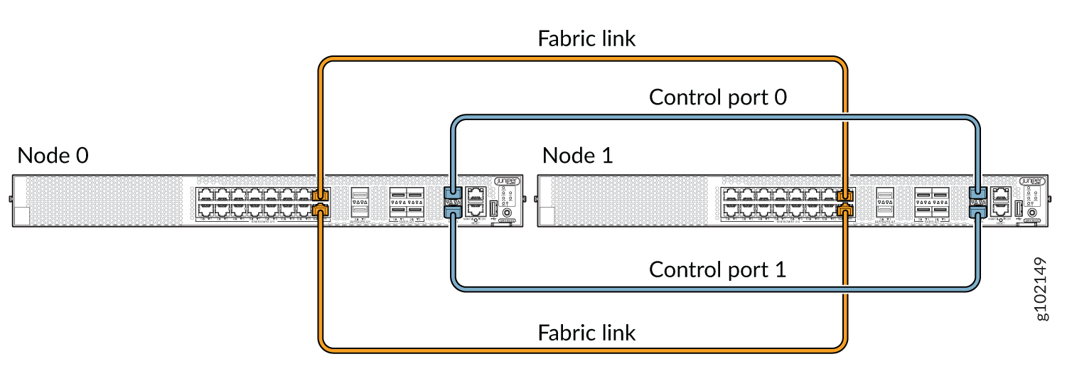
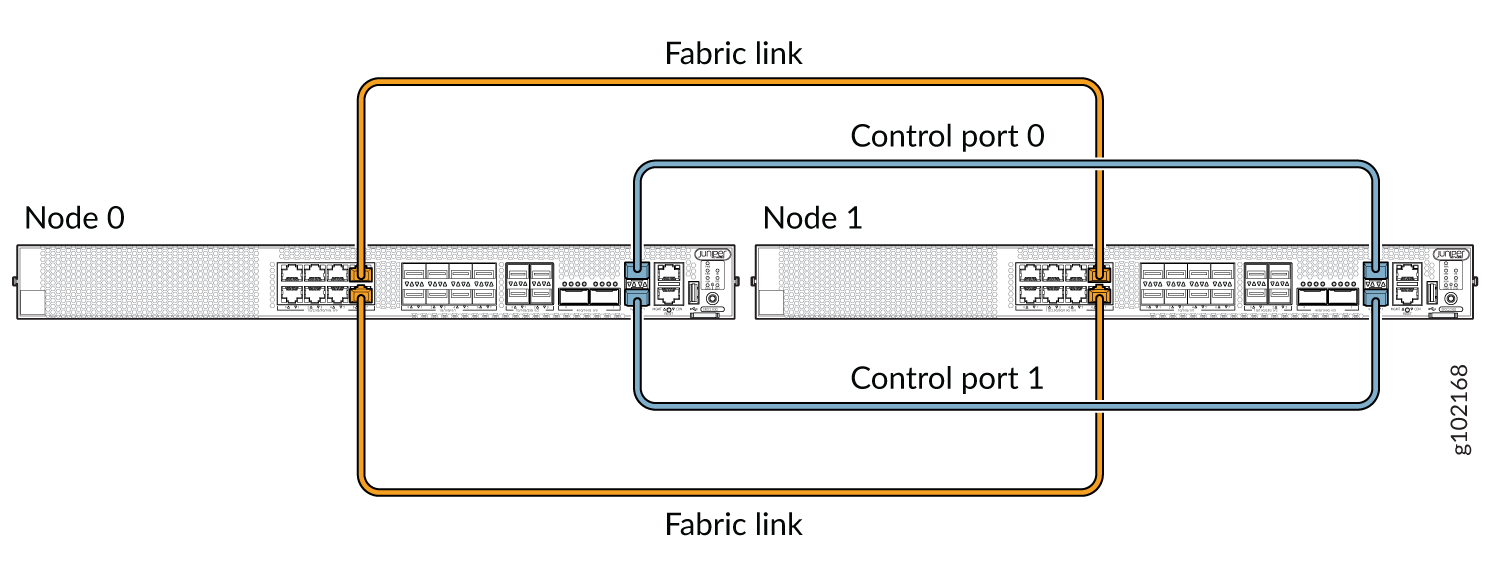
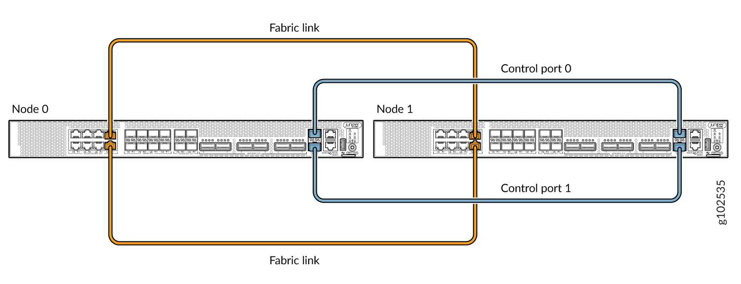
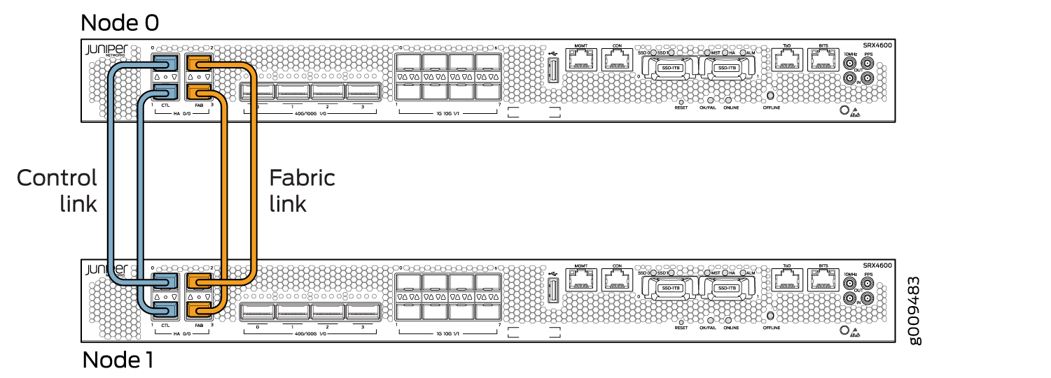
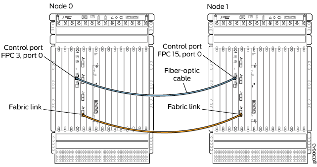
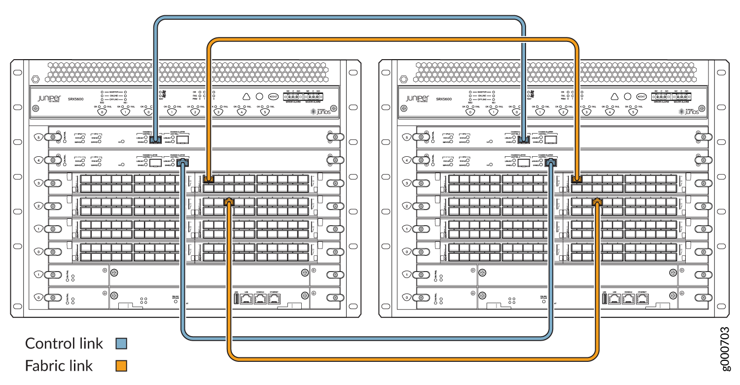
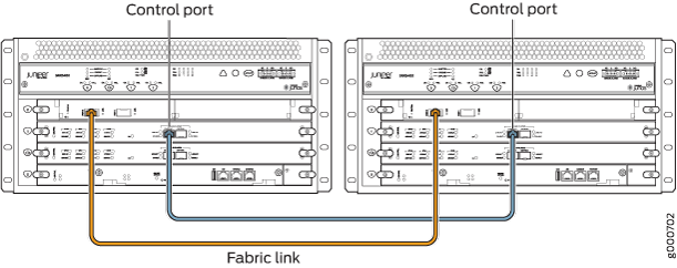
A chassis cluster is created by physically connecting two identical, cluster-supported Firewalls using a pair of Ethernet connections of the same type. These connections provide both the control link and the fabric (data) link between the two devices.
Control Links
In a chassis cluster, control links are established using specific, dedicated ports on each firewall. The interface numbering for these control links changes based on the cluster offset (cluster index).
Control link interfaces follow the naming format:
-
type-fpc/pic/port
For example, ge-1/0/1
In this example:
-
ge indicates the interface type (Gigabit Ethernet).
-
1 represents the cluster index, which also corresponds to the Flexible PIC Concentrator (FPC) number.
-
0 is the Physical Interface Card (PIC) number.
-
1 is the port number.
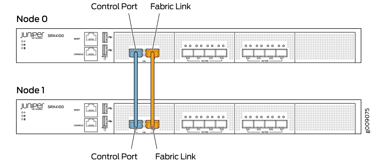
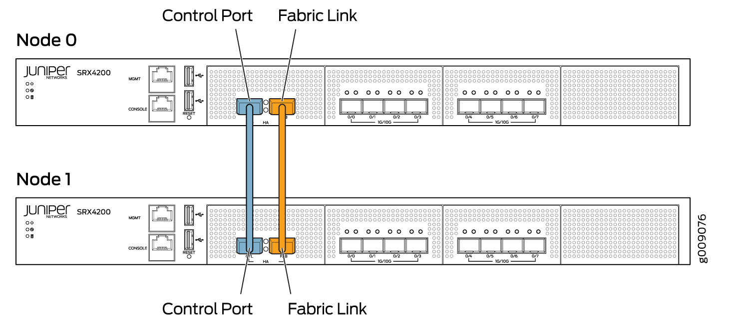
Service Processing Cards (SPCs) provide two dedicated ports—HA0 and HA1—specifically designed for connecting control links between nodes in a chassis cluster.
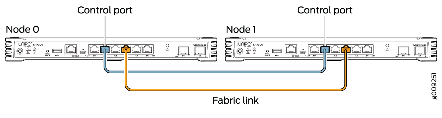
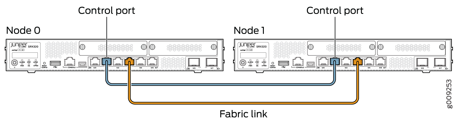
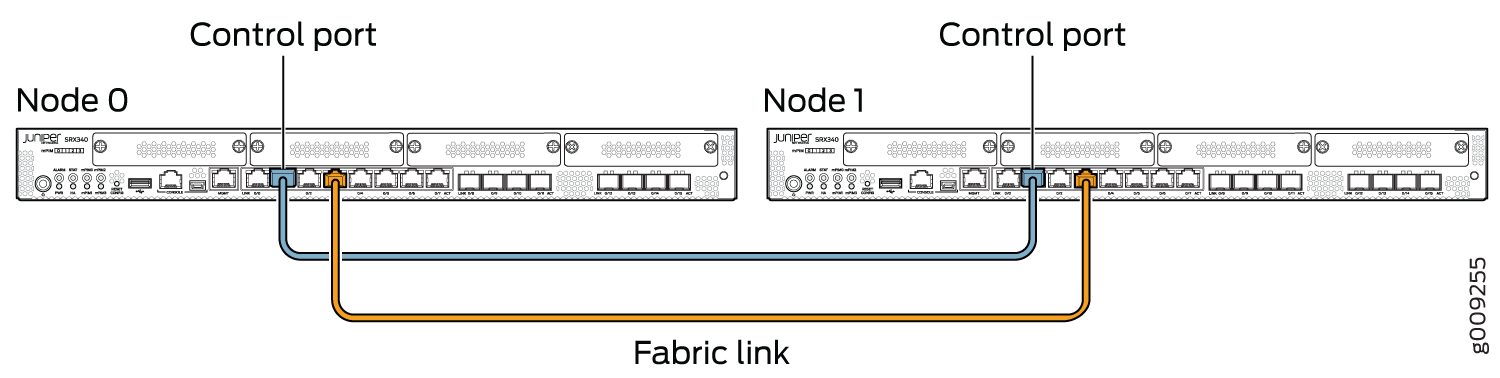
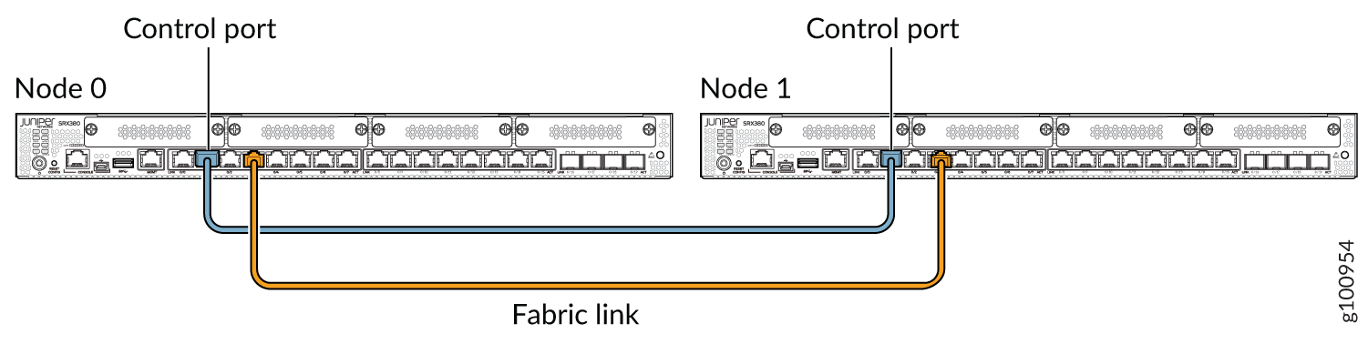
How to Connect Firewalls
You can view the Firewalls connected as pairs, with fabric links and control links between them.


Platform-Specific Control Links Behavior
Use Feature Explorer to confirm platform and release support for specific features.
Use the following table to review platform-specific behaviors for your platforms
|
Platform |
Difference |
|---|---|
|
SRX Series |
Firewalls that support chassis cluster, use the following ports to form the control link on the following Firewalls:
Firewalls that support chassis cluster, use the following ports to form the fabric link on the following Firewalls:
Figure 14 shows dual control links connected using two SPC3 cards and dual fabric links using IOC cards. |