Chassis Cluster Configuration Overview
Following are the prerequisites for configuring a chassis cluster:
-
On SRX300, SRX320, SRX340, SRX345, and SRX380 Firewalls, any existing configurations associated with interfaces that transform to the fxp0 management port and the control port should be removed. For more information, see Understanding SRX Series Chassis Cluster Slot Numbering and Physical Port and Logical Interface Naming.
-
Confirm that hardware and software are the same on both devices.
-
Confirm that license keys are the same on both devices.
-
For SRX300, SRX320, SRX340, SRX345, and SRX380 Firewalls, the placement and type of GPIMs, XGPIMs, XPIMs, and Mini-PIMs (as applicable) must match in the two devices.
-
For SRX5000 line of Firewalls, the placement and type of SPCs must match in the two devices.
Figure 1 shows a chassis cluster flow diagram for Firewalls.
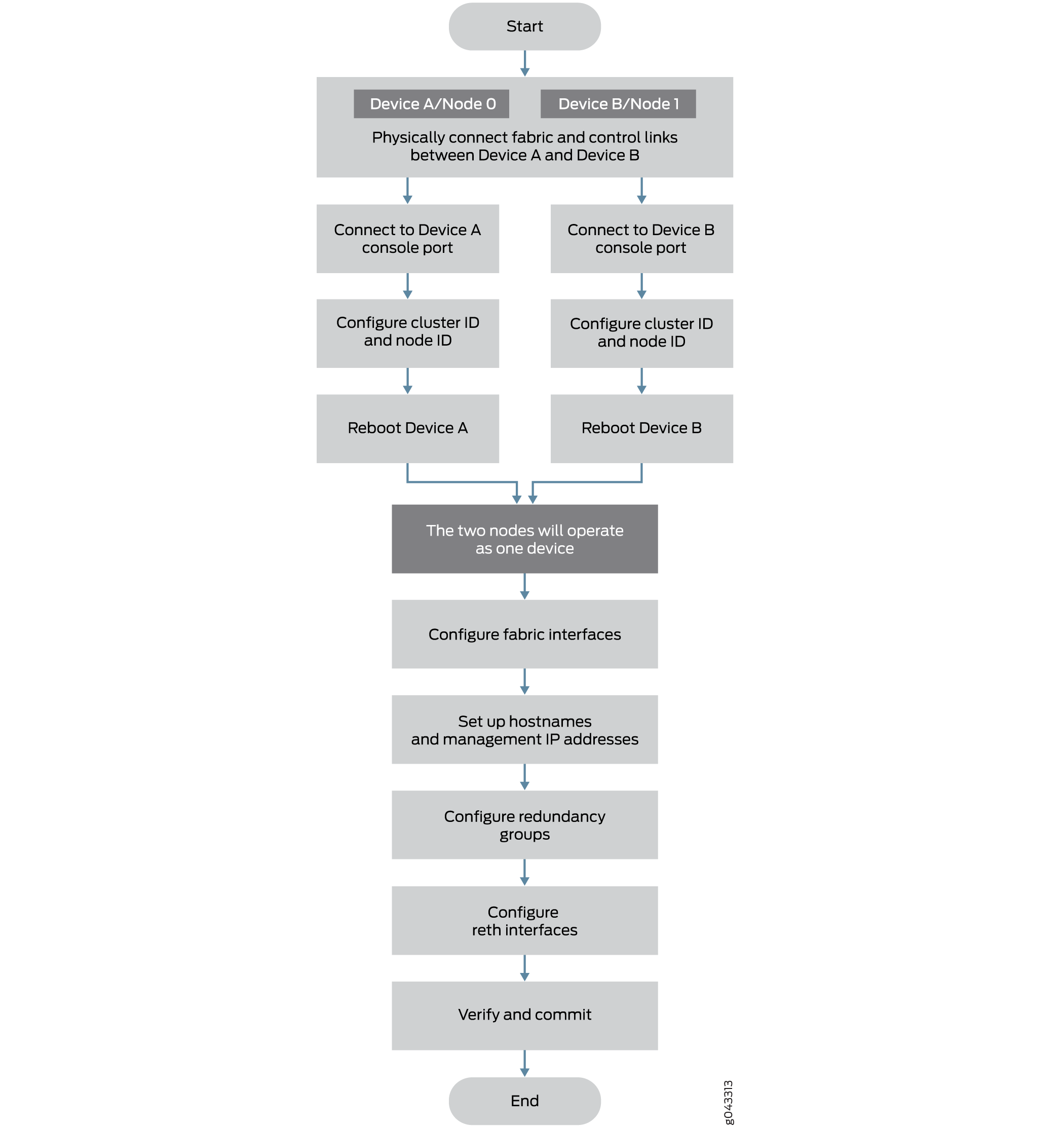
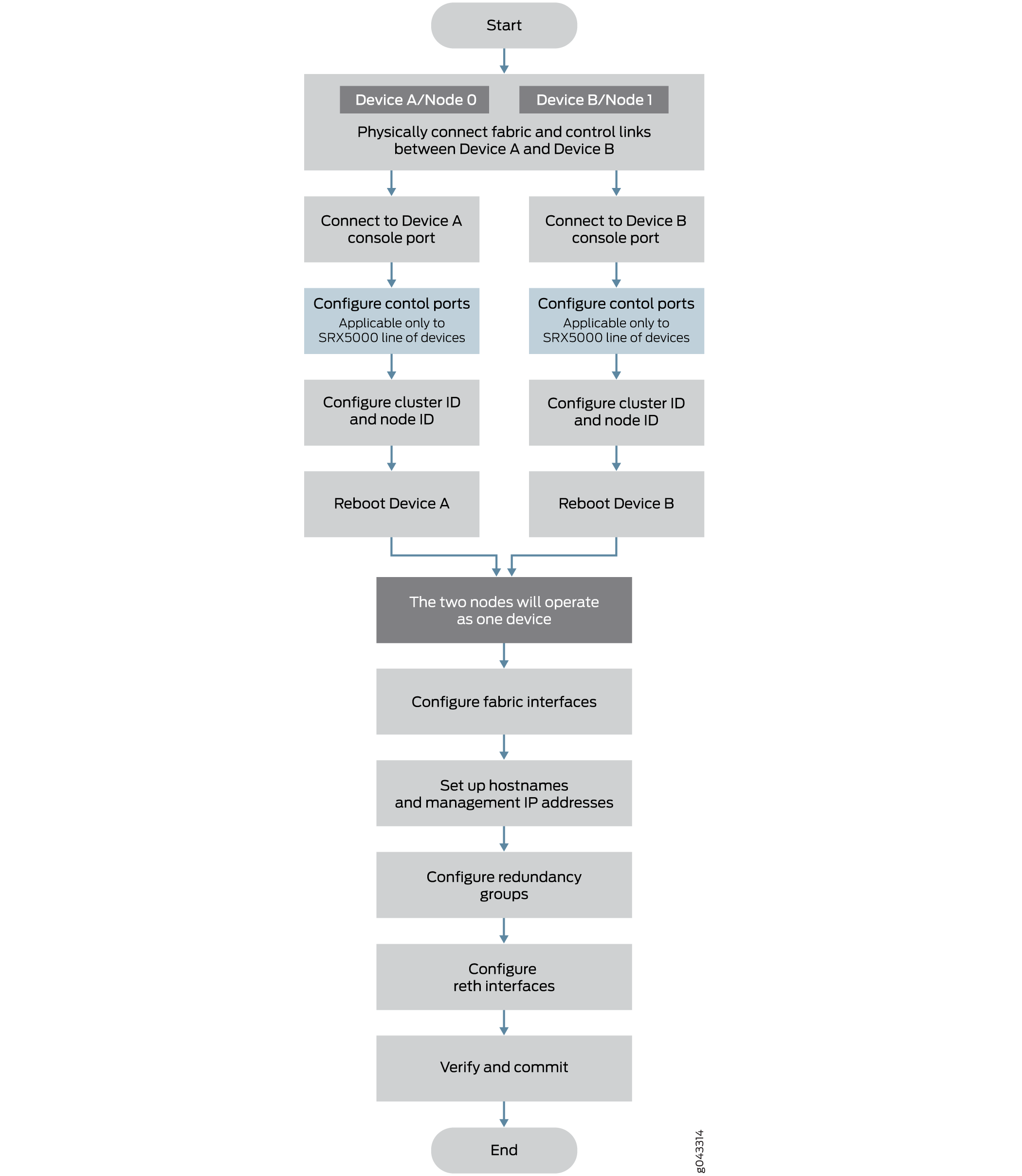
This section provides an overview of the basic steps to create a chassis cluster. To create a chassis cluster:
If two nodes are connected in cluster, one node is elected as primary mode and its Routing Engine is running as primary. The Routing Engine in secondary node running as client. All FPCs in the cluster, regardless in primary node or secondary node, connect to the primary Routing Engine. The FPCs on secondary node connect to primary Routing Engine through the HA control link. If the cluster has two primaries, IOC receives a message from a different primary and reboot itself to recover from this error state.
To prevent the IOC card from rebooting, secondary node has to be powered off before connecting into the cluster.
To preserve the traffic on primary while connecting the secondary node into cluster, it is recommended to configure cluster mode on node 1 and power down before connecting it to the cluster to avoid any impact to the primary. The reason here is that control networks are different for a HA cluster or a single node system. When the control ports are connected, these two join the same network and they exchange messages.
This section provides an overview of the basic steps to restore the backup node after a failure when there is a running primary node:
-
Connect to the console port on the other device (node 1) and use CLI operational mode commands to enable clustering:
-
Identify the cluster that the device is joining by setting the same cluster ID you set on the first node.
-
Identify the node by giving it its own node ID and then reboot the system.
See Example: Setting the Node ID and Cluster ID for Security Devices in a Chassis Cluster . For connection instructions, see the Getting Started Guide for your device
-
-
Power off the secondary node.
-
Connect the HA control ports between two nodes.
-
Power on the secondary node.
-
The cluster is re-formed and the session is synced to the secondary node.
-
When using dual fabric link functionality, connect the two pairs of Ethernet interfaces that you will use on each device. See Understanding Chassis Cluster Dual Fabric Links.
-
When using dual control link functionality (SRX5600 and SRX5800 devices only), connect the two pairs of control ports that you will use on each device.
See Dual Control Link Connections for SRX Series Firewalls in a Chassis Cluster.
For SRX5600 and SRX5800 devices, control ports must be on corresponding slots in the two devices. Table 1 shows the slot numbering offsets:
Table 1: Slot Numbering Offsets Device
Offset
SRX5800
12 (for example, fpc3 and fpc15)
SRX5600
6 (for example, fpc3 and fpc9)
SRX5400
3 (for example, fpc3 and fpc6)
SRX4600
7 (for example, fpc1 and fpc8)