
Chassis Cluster Redundancy Group Failover
Learn how a redundancy group (RG) manages a collection of objects across both nodes in a chassis cluster. Each redundancy group operates as an independent failover unit and is primary on only one node at a time.
Redundancy Group Failover
A Chassis cluster uses multiple highly efficient failover mechanisms to improve overall system reliability and operational continuity.
A redundancy group is a collection of related objects that fail over together. Each
redundancy group monitors a defined set of objects, such as physical interfaces, with each
monitored object assigned a weight. Every redundancy group starts with an initial threshold
of 255. When a monitored object fails, its assigned weight is subtracted
from the redundancy group's threshold. When the threshold value reaches zero, the
redundancy group fails over to the peer node, and all objects associated with that
redundancy group fail over as well.
Additionally, graceful restart of routing protocols enables the Firewalls to minimize traffic disruption during a failover event.
Back-to-back failovers of a redundancy group within a short period can cause unstable and unpredictable cluster behavior. To prevent this, you can configure a failover dampening interval, also known as the hold-down interval.
When a failover occurs, the former primary node of a redundancy group transitions to the secondary-hold state and remains in that state for the duration of the configured hold-down interval. After the hold-down interval expires, the node transitions to the secondary state.
Configuring a hold-down interval prevents additional failovers from occurring during the specified period, thereby improving failover stability.
The hold-down interval applies to both manual failovers and automatic failovers triggered by monitoring failures.
The default failover dampening time for redundancy group 0 is 300 seconds (5 minutes) and
can be configured upto 1800 seconds using the hold-down-interval
statement. In some deployments, —such as those with a large number of routes or logical
interfaces— the default or user-configured interval might be insufficient. In these cases,
the system automatically extends the dampening time in 60-second increments until it
determines that the system is ready to perform a failover.
Redundancy groups x (numbered 1 through 128) have a default failover dampening time of 1 second, which can be configured in the range of 0 to 1800 seconds.
On Firewalls, chassis cluster failover performance is optimized to scale with an increasing number of logical interfaces. Previously, during a redundancy group failover, gratuitous arp (GARP) messages were sent by the Juniper Services Redundancy Protocol (jsrpd) running on the Routing Engine (RE) for each logical interface to redirect traffic to the appropriate node. As the number of logical interfaces increased, the Routing Engine became a scalability bottleneck. To address this, GARP messages are now sent directly from the Services Processing Unit (SPU), improving failover performance and scalability.
Preemptive Failover Delay Timer
At any given time, a redundancy group is in the primary (active) state on one node and in the secondary (backup) state on the peer node.
You can enable the preemptive behavior for a redundancy group on both nodes and assign a priority value to each node. The node with the higher configured priority is initially elected as the primary, while the other node becomes the secondary.
When a redundancy group transitions between the primary and secondary states, there is a possibility that another state transition may occur shortly afterward. Such rapid state changes can result in state flapping between the primary and secondary nodes.
To address this behavior, a failover delay timer was introduced on Firewalls operating in a chassis cluster. This timer helps limit redundancy group flapping by delaying preemptive failovers between the primary and secondary nodes.
To prevent redundancy group state flapping, you can configure the following preemptive failover parameters:
-
Preemptive delay–Specifies the amount of time a redundancy group in the secondary state waits before transitioning to the primary state during a preemptive failover when the primary becomes unavailable. This delay prevents immediate failover and can be configured from 1 to 21,600 seconds.
-
Preemptive limit–Restricts the maximum number of preemptive failoversallowed during a specified preemptive period when
preemptionis enabled for a redundancy group. The configurable range is 1 to 50 failovers. -
Preemptive period–Defines the time window, configurable from 1 to 1440 seconds, during which the preemptive limit is enforced. Only the configured number of preemptive failovers is permitted within this period.
Consider a scenario in which the preemptive period is configured as 300 seconds and the preemptive limit is set to 50.
When the preemptive limit is configured to 50, the preempt count starts at 0 and increments with each preemptive failover. This process continues until the count reaches the configured limit of 50 before the preemptive period expires. Once the preemptive limit is exceeded, preemptive failovers are blocked, and you must manually reset the preempt count to allow further preemptive failovers.
If the preemptive period is configured as 300 seconds and the time elapsed between the first preemptive failover and the current failover exceeds 300 seconds—provided the preemptive limit has not yet been reached—the preemptive period is reset. After the reset, the most recent failover is treated as the first preemptive failover of a new preemptive period, and the process begins again.
The preemptive delay can be configured independently of the preemptive failover limi, and configuring the preemptive delay timer does not alter existing preemptive behavior.
This enhancement allows administrators to introduce a controlled failover delay, which helps reduce the frequency of failovers and results in a more stable network state by minimizing active /standby flapping within a redundancy group.
- Transition from Primary State to Secondary State with Preemptive Delay
- Configure Preemptive Delay Timer
Transition from Primary State to Secondary State with Preemptive Delay
Consider the following example in, which a redundancy group, currently primary on
node 0, is ready for a preemptive transition during a failover. A priority is
assigned to each node, and preemptive option is enabled for the
redundancy group.
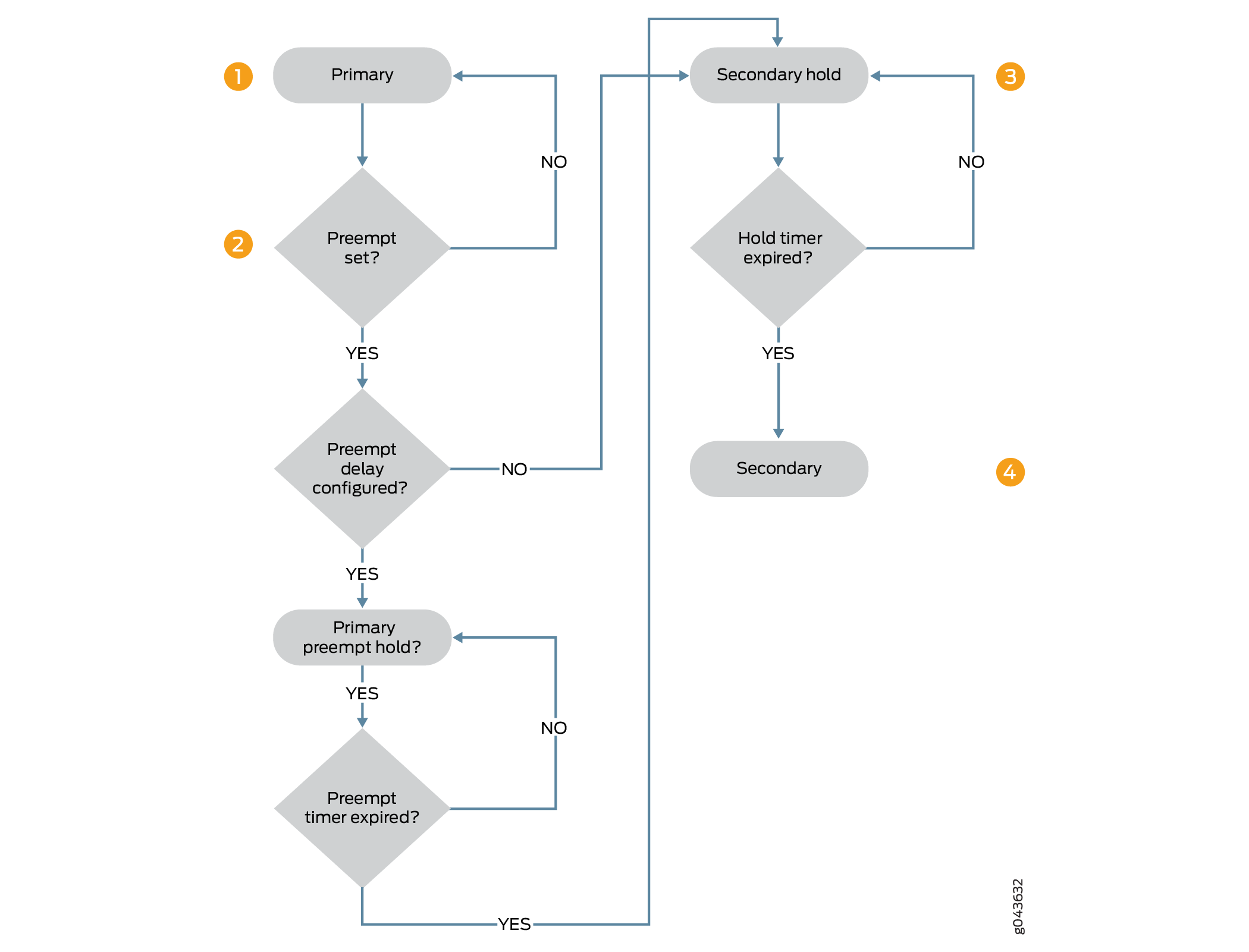
This example Figure 1 illustrates the sequence of events that occur as the redundancy group transitions from the primary state to the secondary state when a preemptive delay timer is configured.
-
A node in the primary state is eligible for a preemptive transition to the secondary state when
preemptiveoption is enabled and the node currently in the secondary state has a higher priority than the primary node. If a preemptive delay is configured, the primary node transitions to the primary-preempt-hold state . If no preemptive delay is configured, the node transitions immediately to the secondary state. -
While in the primary-preempt-hold state, the node waits for the preemptive delay timer to expire. During this time, the state transition is held, and no role change occurs. The node remains in the primary-preempt-hold state until the timer expires.
-
After the preemptive delay expires, the node transitions from the primary-preempt-hold state to secondary-hold state, and then to the secondary state.
-
The node remains in the secondary-hold state for the default duration of 1 second or for the configured hold-down interval (with a minimum of 300 seconds). Once this interval expires, the node transitions fully to the secondary state.
If your chassis cluster experiences an unusually high number of failovers or state flaps, verify that link and monitoring timers are configured appropriately. In high-latency network environments, take extra care when tuning these timers to avoid false failure detection and unnecessary failovers.
Configure Preemptive Delay Timer
This topic explains how to configure the preemptive delay timer on Firewalls in a chassis cluster. Back-to-back redundancy group failovers that occur within a short interval can lead to unstable and unpredictable cluster behavior. Configuring a delay timer and failover rate limit helps prevent this condition by delaying immediate failover for a specified period of time.
To configure the preemptive delay timer and failover rate limit between redundancy group failovers:
-
Enable preemptive failover for a redundancy group and configure a preemptive delay timer ranging from 1 to 21,600 seconds. The default delay value is 1 second.
{primary:node1} [edit chassis cluster redundancy-group number preempt] user@host# set delay interval -
Configure a preemptive failover limit by specifying the maximum number of preemptive failovers, configurable from 1 to 50, and the time period during which the limit is enforced, configurable from 1 to 1440 seconds.
{primary:node1}[edit chassis cluster redundancy-group number preempt]
user@host# set limit limit period period
In the following example, the preemptive delay is set to 300 seconds, and the preemptive limit is set to 10 within a premptive period of 600 seconds. This configuration delays an immediate preemptive failover by 300 seconds and limits the number of preemptive failovers to a maximum of 10 within a 600-second interval.
{primary:node1}[edit chassis cluster redundancy-group 1 preempt]
user@host# set delay 300 limit 10 period 600
You can use the clear chassis cluster preempt-count command to reset
the preempt failover counter for all redundancy groups. When a preemptive limit is
configured, the counter starts at zero and increments with each preemptive failover.
This continues until the counter reaches the configured limit before the preemptive
period expires. Running this command clears the counter and allows the preemptive
failover process to restart.
See Also
Chassis Cluster Redundancy Group Manual Failover
You can manually initiate a failover for redundancy group x (redundancy groups numbered 1 through 128). A manual failover remains in effect until a failback event occurs.
For example, suppose you manually trigger a failover of redundancy group 1 from node 0 to node 1. If an interface monitored by redundancy group 1 subsequently fails, causing the threshold value of the new primary redundancy group drop to zero, this condition is treated as a failback event, and control returns to the original primary node.
You can also manually initiate a failover for redundancy group 0 if you want to change its primary node. Preemption is not supported for redundancy group 0, so a manual failover is required to change its primary role
When preemption is enabled for a redundancy group, the node with the higher configured priority can initiate a failover to assume the primary role. By default, preemption is disabled. See preempt (Chassis Cluster).
When you perform a manual failover for redundancy group 0, the node currently in the primary state transitions to the secondary-hold state. The node remains in the secondary-hold state for the default or configured hold-down interval (with a minimum of 300 seconds) and then transitions to the secondary state.
The following sections describe the state transitions that occur when one node is in the secondary-hold state and the peer node reboots, or when the control link or fabric link to that node is lost.
-
Reboot case—The node in the secondary-hold state transitions to the primary state; the peer node becomes inactive (dead).
-
Control link failure case—The node in the secondary-hold state transitions to the ineligible state and then to the disabled state, while the peer node transitions to the primary state.
-
Fabric link failure case—The node in the secondary-hold state transitions directly to the ineligible state.
During an in-service software upgrade (ISSU), the state transitions described earlier do not occur. Instead, the peer (primary) node transitions directly to the secondary state because Junos OS releases earlier than 10.0 do not recognize or interpret the secondary-hold state. When initiating an ISSU, if one or more redundancy groups on a node are in the secondary-hold state, you must wait for them to transition to the secondary state before performing manual failovers to make all redundancy groups primary on a single node.
Use manual failovers for redundancy group 0 with caution. A redundancy group 0 failover triggers a Routing Engine (RE) failover, during which all processes running on the current primary node are terminated and restarted on the new primary Routing Engine. This operation can result in loss of operational state, such as routing information, and may degrade system performance due to increasedprocess churn.
In some earlier Junos OS releases, it was possible to manually fail over redundancy groups x to a node with a priority value of 0.
Before
performing
a manual failover,
it
is recommend that you
verify redundancy
group nodes
priorities using the show chassis cluster status
command.
However, , the manual failover readiness check has been enhanced and made more restrictive. With this enhancement, you cannot initiate a manual failover to a node with a priority of 0. This behavior prevents unexpected traffic loss caused by attempting to fail over to a node that is not ready to accept traffic.
Initiate a Chassis Cluster Manual Redundancy Group Failover
Before you begin, complete the following tasks:
You can manually
initiate a failover using
the
request
command. A manual failover temporarily
increases
the
priority of the redundancy group for
the
selected
node
to
255, causing
that node to become primary.
Use manual failovers for redundancy group 0 with caution. A redundancy group 0 failover triggers a Routing Engine (RE) failover, during which all processes running on the current primary node are terminated and restarted on the new primary Routing Engine. This action can result in loss of operational state, such as routing information, and may degrade system performance due to increased system churn.
Initiating a chassis cluster redundancy group failover by unplugging the power cord or holding the power button can lead to unpredictable behavior and is not recommended.
For redundancy groups x (numbered 1 through 128), it is possible to manually initiate a failover to a node with a priority value of 0. Before performing a manual failover, it is recommended that you verify the node priorities for the redundancy group to avoid unintended behavior.
Use the show command to display the
status of nodes in the cluster:
{primary:node0}
user@host> show chassis cluster status redundancy-group 0
Cluster ID: 9
Node                  Priority          Status    Preempt  Manual failover

Redundancy group: 0 , Failover count: 1
    node0                   254         primary        no       no
    node1                   1           secondary      no       no
The output of this command indicates that node 0 is currently the primary node.
To trigger a manual
failover and make node 1 the primary,
use
the request
command as
shown
below:
{primary:node0}
user@host> request chassis cluster failover redundancy-group 0 node 1
- - - - - - - - - - - - - - - - - - - - - - - - - - - - - - - - - - - - - - - -
Initiated manual failover for redundancy group 0
Use the show command to display the
new status of nodes in the cluster:
{secondary-hold:node0}
user@host> show chassis cluster status redundancy-group 0
Cluster ID: 9
Node                  Priority          Status    Preempt  Manual failover

Redundancy group: 0 , Failover count: 2
    node0                   254         secondary-hold no       yes
    node1                   255         primary        no       yes
The output of this command indicates that node 1 is currently the primary, and node 0 is in the secondary-hold state. After 5 minutes, node 0 transitions to the secondary state.
You can manually
reset
failover
for redundancy groups
using
the request command. This
action
is
synchronized
the
entire chassis
cluster.
{secondary-hold:node0}
user@host> request chassis cluster failover reset redundancy-group 0
node0:
--------------------------------------------------------------------------
No reset required for redundancy group 0.

node1:
--------------------------------------------------------------------------
Successfully reset manual failover for redundancy group 0
You cannot initiate another failover until the 5-minute hold-down interval has expired.
{secondary-hold:node0}
user@host> request chassis cluster failover redundancy-group 0 node 0
node0:
--------------------------------------------------------------------------
Manual failover is not permitted as redundancy-group 0 on node0 is in secondary-hold state.
Use the show command to display the
current
status of the
nodes in the cluster:
{secondary-hold:node0}
user@host> show chassis cluster status redundancy-group 0
Cluster ID: 9
Node                  Priority          Status    Preempt  Manual failover

Redundancy group: 0 , Failover count: 2
    node0                   254         secondary-hold no       no
    node1                   1           primary        no       no
The output of this command indicates that no back-to-back failover has occurred on either node.
After
performing
a manual failover, you must issue the reset failover command before
requesting another failover.
When the primary node fails and subsequently recovers, the election of the primary node follows the standard selection criteria, based on configured priority values and preemption settings.
Example: Configure Dampening Time Between Back-to-Back Redundancy Group Failovers
This example shows how to configure the dampening time between consecutive redundancy group failovers in a chassis cluster. Redundancy group failovers that occur too frequently can cause unstable and unpredictable cluster behavior, and configuring a dampening interval helps prevent such back-to-back failovers.
Requirements
Before you begin:
Understand redundancy group failover. See Understanding Chassis Cluster Redundancy Group Failover .
Understand redundancy group manual failover. See Understanding Chassis Cluster Redundancy Group Manual Failover.
Overview
The dampening time defines the minimum interval allowed between consecutive failovers for a redundancy group. This interval applies to both manual failovers and automatic failovers triggered by interface monitoring failures.
In this example, the minimum interval between back-to-back failovers is set to 420 seconds for redundancy group 0.
Configuration
Procedure
Step-by-Step Procedure
To configure the dampening time between back-to-back redundancy group failovers:
Configure the dampening time for the redundancy group.
{primary:node0}[edit]
user@host# set chassis cluster redundancy-group 0 hold-down-interval 420
After completing the configuration, commit the changes.
{primary:node0}[edit]
user@host# commit
SNMP Failover Traps for Chassis Cluster Redundancy Group Failover
Chassis clustering supports SNMP traps that are generated whenever a redundancy group failover occurs.
These trap messages aid in troubleshooting failover events and include the following information:
Cluster ID and node ID
Reason for the failover
Redundancy group involved in the failover
The redundancy group’s previous state and current state
At any given time, a cluster node can be in one of the following states: hold, primary, secondary-hold, secondary, ineligible, or disabled. SNMP traps are generated for the following state transitions (with the exception that transitions from the hold state do not trigger a trap):
primary <–> secondary
primary –> secondary-hold
secondary-hold –> secondary
secondary –> ineligible
ineligible –> disabled
ineligible –> primary
secondary –> disabled
A state transition can be triggered by various events, including interface monitoring, SPU monitoring, hardware or software failures, and manual failovers.
If the outgoing interface resides on a node different from the one hosting the Routing Engine that generates the SNMP trap, the trap is forwarded over the control link.
You can enable
trace logging
for these events by
configuring the
traceoptions flag snmp statement.
Verify Chassis Cluster Failover Status
Purpose
Display the failover status of a chassis cluster.
Action
From the CLI, enter the show chassis cluster status command:
{primary:node1}
user@host> show chassis cluster status
Cluster ID: 3
    Node name               Priority    Status    Preempt  Manual failover

	Redundancy-group: 0, Failover count: 1
    node0                   254         primary   no       no
    node1                   2           secondary no       no

	Redundancy-group: 1, Failover count: 1
    node0                   254         primary   no       no
    node1                   1           secondary no       no
{primary:node1}
user@host> show chassis cluster status
Cluster ID: 15
Node                  Priority          Status    Preempt  Manual failover

Redundancy group: 0 , Failover count: 5
    node0                   200         primary        no       no
    node1                   0           lost           n/a      n/a

Redundancy group: 1 , Failover count: 41
    node0                   101         primary        no       no
node1 0 lost n/a n/a{primary:node1}
user@host> show chassis cluster status
Cluster ID: 15
Node Priority Status Preempt Manual failover
Redundancy group: 0 , Failover count: 5
node0 200 primary no no
node1 0 unavailable n/a n/a
Redundancy group: 1 , Failover count: 41
node0 101 primary no no
node1 0 unavailable n/a n/a
Clear Chassis Cluster Failover Status
To clear the failover status of a chassis cluster, enter the clear chassis cluster failover-count command from the CLI:
{primary:node1}
user@host> clear chassis cluster failover-count
Cleared failover-count for all redundancy-groups