Chassis Cluster Redundant Ethernet Interfaces
This topic explains that a redundant Ethernet (reth) interface is a pseudo‑interface that includes at least one physical interface from each node in a cluster. In a chassis cluster configuration, the reth interface on the active node is responsible for forwarding traffic.
Use Feature Explorer to confirm platform and release support for specific features.
Review the Platform-Specific Redundant Ethernet Interfaces Behavior section for notes related to your platform.
See the Additional Platform Information section for more information.
Redundant Ethernet Interfaces
A redundant Ethernet (reth) interface must include, at minimum, a pair of Fast Ethernet interfaces or a pair of Gigabit Ethernet interfaces, referred to as child interfaces of the reth interface (the redundant parent). If two or more child interfaces from each node are assigned to the reth interface, a redundant Ethernet link aggregation group can be formed.
A redundant Ethernet (reth) interface provides link redundancy by grouping multiple physical Ethernet interfaces from different cluster nodes into a single logical interface.
A reth interface must include, at minimum, one pair of physical Ethernet interfaces—one from each node in the chassis cluster. These physical interfaces are referred to as child interfaces, and the logical reth interface is referred to as the parent interface.
Interface Requirements and Restrictions
-
A redundant Ethernet interface must be configured using matching interface types and speeds on both nodes.
Supported combinations include:
-
Fast Ethernet interfaces
-
Gigabit Ethernet interfaces
-
Mixing different Ethernet interface types or speeds within a single reth interface is not supported.
-
Firewalls do not support combining Fast Ethernet and Gigabit Ethernet interfaces in the same redundant Ethernet bundle.
-
If two or more child interfaces from each node are assigned to a single reth interface, the configuration operates as a redundant Ethernet link aggregation group.
Configuration Guidelines
- In configuration statements, a redundant Ethernet interface is referenced using the
rethprefix (for example, reth0). - Child interfaces are associated with the redundant Ethernet interface as part of the child interface configuration.
- A child interface inherits most of its configuration parameters from its redundant Ethernet parent interface.
The maximum number of redundant Ethernet interfaces supported varies by device type, as shown in Additional Platform Information. The number of redundant Ethernet interfaces configured on a device determines the number of redundancy groups that can be created on the Firewalls.
Promiscuous Mode Support
-
You can enable promiscuous mode on reth interfaces. On a Layer 3 Ethernet interface, this mode forwards all received packets on the interface to the central point, or Services Processing Unit (SPU), regardless of the packet's destination MAC address. For redundant Ethernet interfaces, enabling promiscuous mode automatically applies it to associated child physical interfaces.
To enable promiscuous mode on a redundant Ethernet interface, use the
promiscuous-mode statement at the [edit
interfaces] hierarchy.
A redundant Ethernet interface inherits its failover behavior from the redundancy group
x to which it is assigned. The redundant Ethernet interface remains active as
long as its primary child interface on the active node is operational. For example, if
reth0 is associated with redundancy group 1 and redundancy group 1
is active on node 0, reth0 remains operational as long as the node 0
child interface of reth0 is UP.
When deploying Firewalls in chassis cluster mode, it is not recommended to configure local interfaces, or any combination of local interfaces, together with reth interfaces.
For example:
The following configuration shows a chassis cluster with redundant Ethernet interfaces in which some interfaces are configured as local interfaces:
ge-2/0/2 {
    unit 0 {
        family inet {
            address 10.1.1.1/24;
        }
    }
}
The following configuration of chassis cluster redundant Ethernet interfaces, in which interfaces are configured as part of redundant Ethernet interfaces, is supported:
interfaces {
    ge-2/0/2 {
        gigether-options {
            redundant-parent reth2;
        }
    }
    reth2 {
        redundant-ether-options {
            redundancy-group 1;
        }
        unit 0 {
            family inet {
                address 10.1.1.1/24;
            }
        }
    }
}
You can enable promiscuous mode on redundant Ethernet interfaces. When promiscuous mode is enabled on a Layer 3 Ethernet interface, all packets received on the interface are sent to the central point or Services Processing Unit (SPU), regardless of the destination MAC address of the packet. If you enable promiscuous mode on a redundant Ethernet interface, promiscuous mode is then enabled on any child physical interfaces.
To enable promiscuous mode on a redundant Ethernet interface, use the
promiscuous-mode statement at the [edit
interfaces] hierarchy.
IP-over-IP Tunneling
IP-IP tunneling is supported over the reth interface when firewalls are deploed in a chassis cluster configuration. Tunneling enables the encapsulation of one IP packet over another IP packet.
The tunnel configuration is created on both the primary and secondary devices. The traffic passing through the IP-IP tunnel is synced from primary device to secondary device. In the event of a failure on the primary device, the tunnel on the secondary device becomes active automatically. The traffic resumes on the secondary device in the event of the failure of the primary.
On firewalls, tunneling protocols use predefined internal logical interfaces that are created automatically by Junos OS during system boot:
- Generic Routing Encapsulation (GRE) tunnels use the gr-0/0/0 interface.
- IP-IP tunnels use the ip-0/0/0 interface. These internal tunnel interfaces are logical in nature and are not associated with any physical interfaces.
See Also
Example: Configure Chassis Cluster Redundant Ethernet Interfaces
This example shows how to configure chassis cluster redundant Ethernet interfaces. A redundant Ethernet interface is a pseudointerface that contains two or more physical interfaces, with at least one from each node of the cluster.
Requirements
Before you begin:
Understand how to set the chassis cluster node ID and cluster ID. See Example: Setting the Chassis Cluster Node ID and Cluster ID.
Set the number of redundant Ethernet interfaces.
Understand how to set the chassis cluster fabric. See Example: Configuring the Chassis Cluster Fabric Interfaces.
Understand how to set the chassis cluster node redundancy groups. See Example: Configuring Chassis Cluster Redundancy Groups.
Overview
After you assign physical Ethernet interfaces to a redundant Ethernet interface, you configure all required settings at the redundant Ethernet (reth) interface level. The associated physical interfaces, referred to as child interfaces, automatically inherit the configuration of the reth parent interface.
If multiple child interfaces are configured under a single redundant Ethernet interface, all child interfaces must operate at the same interface speed.
In configuration commands, a redundant Ethernet interface is identified by the reth prefix (for example, reth0).
- You can enable promiscuous mode on reth interfaces. On a Layer 3 Ethernet interface, this mode forwards all received packets on the interface to the central point, or Services Processing Unit (SPU), regardless of the packet's destination MAC address. For redundant Ethernet interfaces, enabling promiscuous mode automatically applies it to associated child physical interfaces.
To enable promiscuous mode on a redundant Ethernet interface, use the promiscuous-mode statement at the [edit interfaces] hierarchy.
Configuration
- Configure Chassis Cluster Redundant Ethernet Interfaces for IPv4 Addresses
- Configure Chassis Cluster Redundant Ethernet Interfaces for IPv6 Addresses
- Results
Configure Chassis Cluster Redundant Ethernet Interfaces for IPv4 Addresses
CLI Quick Configuration
To quickly configure this example, copy the
following commands, paste them into a text file, remove any line breaks,
change any details necessary to match your network configuration,
copy and paste the commands into the CLI at the [edit] hierarchy
level, and then enter commit from configuration mode.
{primary:node0}[edit]
set interfaces ge-0/0/0 gigether-options redundant-parent reth1
set interfaces ge-7/0/0 gigether-options redundant-parent reth1
set interfaces fe-1/0/0 fast-ether-options redundant-parent reth2
set interfaces fe-8/0/0 fast-ether-options redundant-parent reth2
set interfaces reth1 redundant-ether-options redundancy-group 1
set interfaces reth1 unit 0 family inet mtu 1500
set interfaces reth1 unit 0 family inet address 10.1.1.3/24
set security zones security-zone Trust interfaces reth1.0
Step-by-Step Procedure
To configure redundant Ethernet interfaces for IPv4:
Bind redundant child physical interfaces to reth1.
{primary:node0}[edit]
user@host# set interfaces ge-0/0/0 gigether-options redundant-parent reth1
user@host# set interfaces ge-7/0/0 gigether-options redundant-parent reth1
Bind redundant child physical interfaces to reth2.
{primary:node0}[edit]
user@host# set interfaces fe-1/0/0 fast-ether-options redundant-parent reth2
user@host# set interfaces fe-8/0/0 fast-ether-options redundant-parent reth2
Add reth1 to redundancy group 1.
{primary:node0}[edit]
user@host# set interfaces reth1 redundant-ether-options redundancy-group 1
Set the MTU size.
{primary:node0}[edit]
user@host# set interfaces reth1 unit 0 family inet mtu 1500
The maximum transmission unit (MTU) set on the reth interface can be different from the MTU on the child interface.
Assign an IP address to reth1.
{primary:node0}[edit]
user@host# set interfaces reth1 unit 0 family inet address 10.1.1.3/24
Associate reth1.0 to the trust security zone.
{primary:node0}[edit]
user@host# set security zones security-zone Trust interfaces reth1.0
Configure Chassis Cluster Redundant Ethernet Interfaces for IPv6 Addresses
CLI Quick Configuration
To quickly configure this example, copy the
following commands, paste them into a text file, remove any line breaks,
change any details necessary to match your network configuration,
copy and paste the commands into the CLI at the [edit] hierarchy
level, and then enter commit from configuration mode.
{primary:node0}[edit]
set interfaces ge-0/0/0 gigether-options redundant-parent reth1
set interfaces ge-7/0/0 gigether-options redundant-parent reth1
set interfaces fe-1/0/0 fast-ether-options redundant-parent reth2
set interfaces fe-8/0/0 fast-ether-options redundant-parent reth2
set interfaces reth2 redundant-ether-options redundancy-group 1
set interfaces reth2 unit 0 family inet6 mtu 1500
set interfaces reth2 unit 0 family inet6 address 2010:2010:201::2/64
set security zones security-zone Trust interfaces reth2.0
Step-by-Step Procedure
To configure redundant Ethernet interfaces for IPv6:
Bind redundant child physical interfaces to reth1.
{primary:node0}[edit]
user@host# set interfaces ge-0/0/0 gigether-options redundant-parent reth1
user@host# set interfaces ge-7/0/0 gigether-options redundant-parent reth1
Bind redundant child physical interfaces to reth2.
{primary:node0}[edit]
user@host# set interfaces fe-1/0/0 fast-ether-options redundant-parent reth2
user@host# set interfaces fe-8/0/0 fast-ether-options redundant-parent reth2
Add reth2 to redundancy group 1.
{primary:node0}[edit]
user@host# set interfaces reth2 redundant-ether-options redundancy-group 1
Set the MTU size.
{primary:node0}[edit]
user@host# set interfaces reth2 unit 0 family inet6 mtu 1500
Assign an IP address to reth2.
{primary:node0}[edit]
user@host# set interfaces reth2 unit 0 family inet6 address 2010:2010:201::2/64
Associate reth2.0 to the trust security zone.
{primary:node0}[edit]
user@host# set security zones security-zone Trust interfaces reth2.0
Step-by-Step Procedure
To set the number of redundant Ethernet interfaces for a chassis cluster:
Specify the number of redundant Ethernet interfaces:
{primary:node0}[edit]

user@host# set chassis cluster reth-count 2
Results
From configuration mode, confirm your configuration
by entering the show interfaces command. If the output
does not display the intended configuration, repeat the configuration
instructions in this example to correct it.
For brevity, this show command output includes only
the configuration that is relevant to this example. Any other configuration
on the system has been replaced with ellipses (...).
{primary:node0}[edit]
user@host# show interfaces
interfaces {
    ...
    fe-1/0/0 {
        fastether-options {
            redundant-parent reth2;
        }
    }
    fe-8/0/0 {
        fastether-options {
            redundant-parent reth2;
        }
    }
    ge-0/0/0 {
        gigether-options {
            redundant-parent reth1;
        }
    }
    ge-7/0/0 {
        gigether-options {
            redundant-parent reth1;
        }
    }
    reth1 {
        redundant-ether-options {
            redundancy-group 1;
        }
        unit 0 {
            family inet {
                mtu 1500;
                address 10.1.1.3/24;
            }
        }
    }
    reth2 {
        redundant-ether-options {
            redundancy-group 1;
        }
        unit 0 {
            family inet6 {
                mtu 1500;
                address 2010:2010:201::2/64;
            }
        }
    }
    ...
}
If you are done configuring the device, enter commit from configuration mode.
Verification
Confirm that the configuration is working properly.
Verify Chassis Cluster Redundant Ethernet Interfaces
Purpose
Verify the configuration of the chassis cluster redundant Ethernet interfaces.
Action
From operational mode, enter the show interfaces
terse | match reth1 command:
{primary:node0}
user@host> show interfaces terse | match reth1

ge-0/0/0.0             up    up   aenet    --> reth1.0
ge-7/0/0.0             up    up   aenet    --> reth1.0
reth1                  up    up
reth1.0                up    up   inet     10.1.1.3/24
Verify Chassis Cluster Control Links
Purpose
Verify information about the control interface in a chassis cluster configuration.
Action
From operational mode, enter the show chassis cluster
interfaces command:
{primary:node0}
user@host> show chassis cluster interfaces
Control link status: Up

Control interfaces:
    Index   Interface   Monitored-Status   Internal-SA   Security
    0       em0         Up                 Disabled      Disabled
    1       em1         Up                 Disabled      Disabled

Fabric link status: Up

Fabric interfaces:
    Name    Child-interface    Status                    Security
                               (Physical/Monitored)
    fab0    xe-3/0/6           Up   / Up                 Enabled
    fab0
    fab1    xe-9/0/6           Up   / Up                 Enabled
    fab1

Redundant-ethernet Information:
    Name         Status      Redundancy-group
    reth0        Up          1
    reth1        Up          1
Example: Configure Chassis Cluster Redundant Ethernet Interfaces on SRX4600
This example shows how to configure child links or physical links on SRX4600 device in chassis cluster mode.
Requirements
Before you begin:
Understand how to set the chassis cluster node ID and cluster ID. See Example: Setting the Chassis Cluster Node ID and Cluster ID.
Understand how to set the chassis cluster node redundancy groups. See Example: Configuring Chassis Cluster Redundancy Groups.
Overview
You can configure up to eight number of child links for a reth bundle on SRX4600 devices per chassis.
Configuration
CLI Quick Configuration
To quickly configure this example, copy the
following commands, paste them into a text file, remove any line breaks,
change any details necessary to match your network configuration,
copy and paste the commands into the CLI at the [edit] hierarchy
level, and then enter commit from configuration mode.
{primary:node0}[edit]
set interfaces xe-1/0/0:0 gigether-options redundant-parent reth0
set interfaces xe-1/0/0:1 gigether-options redundant-parent reth0
set interfaces xe-1/0/0:2 gigether-options redundant-parent reth0
set interfaces xe-1/0/0:3 gigether-options redundant-parent reth0
set interfaces xe-1/0/1:0 gigether-options redundant-parent reth0
set interfaces xe-1/0/1:1 gigether-options redundant-parent reth0
set interfaces xe-1/0/1:2 gigether-options redundant-parent reth0
set interfaces xe-1/0/1:3 gigether-options redundant-parent reth0
set interfaces xe-1/1/0 gigether-options redundant-parent reth1
set interfaces xe-1/1/1 gigether-options redundant-parent reth1
set interfaces reth0 redundant-ether-options redundancy-group 1
set interfaces reth0 unit 0 family inet address 192.0.2.1/24
set interfaces reth1 redundant-ether-options redundancy-group 1
set interfaces reth1 redundant-ether-options lacp active
set interfaces reth1 unit 0 family inet address 198.51.100.1/24
set security zones security-zone Trust-zone interfaces reth0.0
set security zones security-zone Untrust-zone interfaces reth1.0
set chassis cluster reth-count 10
Configure redundant Ethernet interfaces
Step-by-Step Procedure
To configure redundant Ethernet interfaces:
Bind eight redundant child physical interfaces to reth0.
{primary:node0}[edit]
user@host# set interfaces xe-1/0/0:0 gigether-options redundant-parent reth0
user@host# set interfaces xe-1/0/0:1 gigether-options redundant-parent reth0
user@host# set interfaces xe-1/0/0:2 gigether-options redundant-parent reth0
user@host# set interfaces xe-1/0/0:3 gigether-options redundant-parent reth0
user@host# set interfaces xe-1/0/1:0 gigether-options redundant-parent reth0
user@host# set interfaces xe-1/0/1:1 gigether-options redundant-parent reth0
user@host# set interfaces xe-1/0/1:2 gigether-options redundant-parent reth0
user@host# set interfaces xe-1/0/1:3 gigether-options redundant-parent reth0
Bind redundant child physical interfaces to reth1.
{primary:node0}[edit]
user@host# set interfaces xe-1/1/0 gigether-options redundant-parent reth1
user@host# set interfaces xe-1/1/1 gigether-options redundant-parent reth1
Specify the number of redundant Ethernet interfaces:
{primary:node0}[edit]

user@host# set chassis cluster reth-count 10
Add reth0 to redundancy group 1.
{primary:node0}[edit]
user@host# set interfaces reth0 redundant-ether-options redundancy-group 1
Assign an IP address to reth0.
{primary:node0}[edit]
user@host# set interfaces reth0 unit 0 family inet address 192.0.2.1/24
Add reth1 to redundancy group1.
{primary:node0}[edit]
user@host# set interfaces reth1 redundant-ether-options redundancy-group 1
user@host# set interfaces reth1 redundant-ether-options lacp active
Assign an IP address to reth1.
{primary:node0}[edit]
user@host# set interfaces reth1 unit 0 family inet address 198.51.100.1/24
Associate reth0.0 to the trust security zone.
{primary:node0}[edit]
user@host# set security zones security-zone Trust-zone interfaces reth0.0
Associate reth1.0 to untrust security zone.
{primary:node0}[edit]
user@host# set security zones security-zone Untrust-zone interfaces reth1.0
Results
From configuration mode, confirm your configuration
by entering the show interfaces command. If the output
does not display the intended configuration, repeat the configuration
instructions in this example to correct it.
For brevity, this show command output includes only
the configuration that is relevant to this example. Any other configuration
on the system has been replaced with ellipses (...).
{primary:node0}[edit]
user@host# show interfaces
xe-1/0/0:0 {
    gigether-options {
        redundant-parent reth0;
    }
}
xe-1/0/0:1 {
    gigether-options {
        redundant-parent reth0;
    }
}
xe-1/0/0:2 {
    gigether-options {
        redundant-parent reth0;
    }
}
xe-1/0/0:3 {
    gigether-options {
        redundant-parent reth0;
    }
}
xe-1/0/1:0 {
    gigether-options {
        redundant-parent reth0;
    }
}
xe-1/0/1:1 {
    gigether-options {
        redundant-parent reth0;
    }
}
xe-1/0/1:2 {
    gigether-options {
        redundant-parent reth0;
    }
}
xe-1/0/1:3 {
    gigether-options {
        redundant-parent reth0;
    }
}
xe-1/1/0 {
    gigether-options {
        redundant-parent reth1;
    }
}
xe-1/1/1 {
    gigether-options {
        redundant-parent reth1;
    }
}
reth0 {
    redundant-ether-options {
        redundancy-group 1;
    }
    unit 0 {
        family inet {
            address 192.0.2.1/24;
        }
    }
}
reth1 {
    redundant-ether-options {
        redundancy-group 1;
        lacp {
            active;
        }
    }
    unit 0 {
        family inet {
            address 198.51.100.1/24;
        }
    }
}
If you are done configuring the device, enter commit from configuration mode.
Verification
Confirm that the configuration is working properly.
Verify Chassis Cluster Redundant Ethernet Interfaces
Purpose
Verify the configuration of the chassis cluster redundant Ethernet interfaces on SRX4600 device.
Action
From operational mode, enter the show interfaces
terse | match reth0 command:
{primary:node0}
user@host> show interfaces terse | match reth0

xe-1/0/0:0.0            up    down aenet    --> reth0.0
xe-1/0/0:1.0            up    down aenet    --> reth0.0
xe-1/0/0:2.0            up    down aenet    --> reth0.0
xe-1/0/0:3.0            up    down aenet    --> reth0.0
xe-1/0/1:0.0            up    down aenet    --> reth0.0
xe-1/0/1:1.0            up    down aenet    --> reth0.0
xe-1/0/1:2.0            up    down aenet    --> reth0.0
xe-1/0/1:3.0            up    down aenet    --> reth0.0
reth0                   up    down
reth0.0                 up    down inet     192.0.2.1/24
Meaning
You can view the maximum number of configured child link interfaces of a reth bundle from four to eight in one chassis.
Verify Chassis Cluster Control Links
Purpose
Verify information about the control interface in a chassis cluster configuration.
Action
From operational mode, enter the show chassis cluster
interfaces command:
{primary:node0}
user@host> show chassis cluster interfaces

Control link status: Down

Control interfaces:
    Index   Interface   Monitored-Status   Internal-SA   Security
    0       em0         Down               Disabled      Disabled
    1       em1         Down               Disabled      Disabled

Fabric link status: Down

Fabric interfaces:
    Name    Child-interface    Status                    Security
                               (Physical/Monitored)
    fab0    xe-0/0/2           Up   / Down               Disabled
    fab0

Redundant-ethernet Information:
    Name         Status      Redundancy-group
    reth0        Down        1
    reth1        Up          1
    reth2        Down        Not configured
    reth3        Down        Not configured
    reth4        Down        Not configured
    reth5        Down        Not configured
    reth6        Down        Not configured
    reth7        Down        Not configured
    reth8        Down        Not configured
    reth9        Down        Not configured

Redundant-pseudo-interface Information:
    Name         Status      Redundancy-group
    lo0          Up          0
Example: Configure IP-over-IP Tunnel on Firewalls
This example shows how to create IP-IP tunnel with a forwarding next-hop to pass IPv4 traffic through the tunnel and synchronize the configuration from primary device to secondary device.
Requirements
Before you begin:
-
Understand how to set the chassis cluster node ID and cluster ID. See Example: Setting the Chassis Cluster Node ID and Cluster ID.
This example uses the following hardware and software components:
-
Junos OS Release 23.1R1 or later version.
-
SRX345 Device
Overview
Packets are routed to an internal interface, where they are encapsulated within an IP packet and forwarded to the destination address of the encapsulated packet. The IP-IP interface is an internal-only interface and is not associated with any physical interface. You must configure the interface to enable IP tunneling.
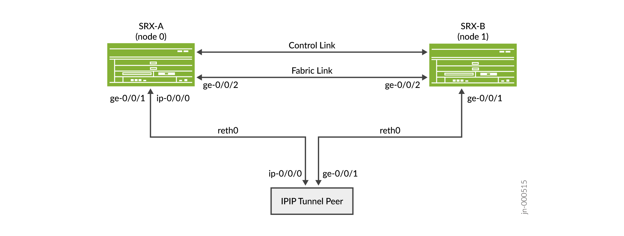
Topology
Figure 1 Illustrates IP-over-IP scenario with Firewalls operating in chassis cluster mode.
Configuration
- Configure IP-IP tunnel with Chassis Cluster Redundant Ethernet Interfaces for IPv4 Addresses
- Results
Configure IP-IP tunnel with Chassis Cluster Redundant Ethernet Interfaces for IPv4 Addresses
CLI Quick Configuration
To quickly configure this example, copy the following commands, paste them into
a text file, remove any line breaks, change any details necessary to match your
network configuration, copy and paste the commands into the CLI at the
[edit] hierarchy level, and then enter
commit from configuration mode.
{primary:node0}[edit]
set chassis cluster reth-count 2
set chassis cluster redundancy-group 0 node 0 priority 100
set chassis cluster redundancy-group 0 node 1 priority 1
set chassis cluster redundancy-group 1 node 0 priority 100
set chassis cluster redundancy-group 1 node 1 priority 1
set interfaces reth0 redundant-ether-options redundancy-group 1
set interfaces reth1 redundant-ether-options redundancy-group 1
set interfaces reth0 unit 0 family inet address 22.0.0.254/24
set interfaces reth1 unit 0 family inet address 1.0.0.254/24
set interfaces ip-0/0/0 unit 0 tunnel source 22.0.0.254
set interfaces ip-0/0/0 unit 0 tunnel destination 22.0.0.200
set interfaces ip-0/0/0 unit 0 family inet address 33.0.0.254/24
set interfaces ge-0/0/1 gigether-options redundant-parent reth0
set interfaces ge-0/0/2 gigether-options redundant-parent reth1
set interfaces ge-7/0/1 gigether-options redundant-parent reth0
set interfaces ge-7/0/2 gigether-options redundant-parent reth1
set interfaces fab0 fabric-options member-interfaces ge-0/0/0
set interfaces fab1 fabric-options member-interfaces ge-7/0/0
{peer}
set interfaces ip-0/0/0 unit 0 tunnel source 22.0.0.200
set interfaces ip-0/0/0 unit 0 tunnel destination 22.0.0.254
set interfaces ip-0/0/0 unit 0 family inet address 33.0.0.200/24
set interfaces ge-0/0/1 unit 0 family inet address 22.0.0.200/24
set interfaces ge-0/0/2 unit 0 family inet address 2.0.0.200/24
set routing-options static route 1.0.0.0/24 next-hop ip-0/0/0.0
Step-by-Step Procedure
To configure redundant Ethernet interfaces for IPv4:
-
Set up redundancy group 0 for the Routing Engine failover properties, and set up redundancy group 1 (all interfaces are in one redundancy group in this example) to define the failover properties for the redundant Ethernet interfaces.
{primary:node0}[edit] user@host# set chassis cluster redundancy-group 0 node 0 priority 100 user@host# set chassis cluster redundancy-group 0 node 1 priority 1 user@host# set chassis cluster redundancy-group 1 node 0 priority 100 user@host# set chassis cluster redundancy-group 1 node 1 priority 1 -
Set up the redundant Ethernet (reth) interfaces.
{primary:node0}[edit] user@host# set chassis cluster reth-count 2 user@host# set interfaces ge-0/0/1 gigether-options redundant-parent reth0 user@host# set interfaces ge-0/0/2 gigether-options redundant-parent reth1 user@host# set interfaces ge-7/0/1 gigether-options redundant-parent reth0 user@host# set interfaces ge-7/0/2 gigether-options redundant-parent reth1 user@host# set interfaces reth0 redundant-ether-options redundancy-group 1 user@host# set interfaces reth0 unit 0 family inet address 22.0.0.254/24 user@host# set interfaces reth1 redundant-ether-options redundancy-group 1 user@host# set interfaces reth1 unit 0 family inet address 1.0.0.254/24 -
Configure tunnel over redundant ethernet interface on both the nodes.
{primary:node0}[edit] user@host# set interfaces ip-0/0/0 unit 0 tunnel source 22.0.0.254 user@host# set interfaces ip-0/0/0 unit 0 tunnel destination 22.0.0.200 user@host# set interfaces ip-0/0/0 unit 0 family inet address 33.0.0.254/24 -
Configure tunnel session on the peer.
{peer} user@host# set interfaces ip-0/0/0 unit 0 tunnel source 22.0.0.200 user@host# set interfaces ip-0/0/0 unit 0 tunnel destination 22.0.0.254 user@host# set interfaces ip-0/0/0 unit 0 family inet address 33.0.0.200/24 user@host# set interfaces ge-0/0/1 unit 0 family inet address 22.0.0.200/24 user@host# set interfaces ge-0/0/2 unit 0 family inet address 2.0.0.200/24 user@host# set routing-options static route 1.0.0.0/24 next-hop ip-0/0/0.0 -
Configure routing-options on both the nodes:
{primary:node0} set routing-options static route 2.0.0.0/24 next-hop ip-0/0/0.0 -
Configure fabric interfaces on both the nodes.
{primary:node0}[edit]
user@host# set interfaces fab0 fabric-options member-interfaces ge-0/0/0
user@host# set interfaces fab1 fabric-options member-interfaces ge-7/0/0
Results
From configuration mode, confirm your configuration by entering the show
interfaces command. If the output does not display the intended
configuration, repeat the configuration instructions in this example to correct
it.
For brevity, this show command output includes only the
configuration that is relevant to this example. Any other configuration on the
system has been replaced with ellipses (...).
{primary:node0}[edit]
user@host# show interfaces
ip-0/0/0 {
    unit 0 {
        tunnel {
            source 22.0.0.254;
            destination 22.0.0.200;
        }
        family inet {
            address 33.0.0.254/24;
        }
    }
}
ge-0/0/1 {
    gigether-options {
        redundant-parent reth0;
    }
}
ge-0/0/2 {
    gigether-options {
        redundant-parent reth1;
    }
}
ge-7/0/1 {
    gigether-options {
        redundant-parent reth0;
    }
}
ge-7/0/2 {
    gigether-options {
        redundant-parent reth1;
    }
}
fab0 {
    fabric-options {
        member-interfaces {
            ge-0/0/0;
        }
    }
}
fab1 {
    fabric-options {
        member-interfaces {
            ge-7/0/0;
        }
    }
}
reth0 {
    redundant-ether-options {
        redundancy-group 1;
    }
    unit 0 {
        family inet {
            address 22.0.0.254/24;
        }
    }
}
reth1 {
    redundant-ether-options {
        redundancy-group 1;
    }
    unit 0 {
        family inet {
            address 1.0.0.254/24;
        }
    }
}
Verification
Purpose
Display the information about chassis cluster interfaces and status.
Action
From operational mode, enter the show chassis cluster
interfaces,show chassis cluster status, and
show security flow session command.
{primary:node0}
user@host> show chassis cluster interfaces
Control link status: Up

Control interfaces:
    Index   Interface   Monitored-Status   Internal-SA   Security
    0       fxp1        Up                 Disabled      Disabled

Fabric link status: Down

Fabric interfaces:
    Name    Child-interface    Status                    Security
                               (Physical/Monitored)
    fab0    ge-0/0/0          Up   / Up                 Disabled
    fab0
    fab1    ge-0/0/7          Up   / Up                 Disabled
    fab1

Redundant-ethernet Information:
    Name         Status      Redundancy-group
    reth0        Up          1
    reth1        Up          1

Redundant-pseudo-interface Information:
    Name         Status      Redundancy-group
    lo0          Up          0
{primary:node0}
user@host> show chassis cluster status
Monitor Failure codes:
    CS  Cold Sync monitoring        FL  Fabric Connection monitoring
    GR  GRES monitoring             HW  Hardware monitoring
    IF  Interface monitoring        IP  IP monitoring
    LB  Loopback monitoring         MB  Mbuf monitoring
    NH  Nexthop monitoring          NP  NPC monitoring
    SP  SPU monitoring              SM  Schedule monitoring
    CF  Config Sync monitoring      RE  Relinquish monitoring
    IS  IRQ storm

Cluster ID: 1
Node   Priority Status               Preempt Manual   Monitor-failures

Redundancy group: 0 , Failover count: 1
node0  200      primary              no      no       None
node1  100      secondary            no      no       None

Redundancy group: 1 , Failover count: 1
node0  200      primary              no      no       None
node1  100      secondary            no      no       None
{primary:node0}
user@host> show security flow session
node0:
--------------------------------------------------------------------------

Session ID: 6323, Policy name: N/A, HA State: Active, Timeout: N/A, Session State: Valid
  In: 2012::2:2/1 --> 2012::2:1/1;ipip, Conn Tag: 0x0, If: reth1.0, Pkts: 0, Bytes: 0,

Session ID: 6324, Policy name: N/A, HA State: Active, Timeout: N/A, Session State: Valid
  In: 2012::2:2/1 --> 2012::2:1/1;ipv6, Conn Tag: 0x0, If: reth1.0, Pkts: 0, Bytes: 0,

Session ID: 6361, Policy name: self-traffic-policy/1, HA State: Active, Timeout: 56, Session State: Valid
  In: fe80::2:2/1 --> ff02::5/1;ospf, Conn Tag: 0x0, If: ip-0/0/0.1, Pkts: 153842, Bytes: 12371296,
  Out: ff02::5/1 --> fe80::2:2/1;ospf, Conn Tag: 0x0, If: .local..0, Pkts: 0, Bytes: 0,

Session ID: 6362, Policy name: self-traffic-policy/1, HA State: Active, Timeout: 52, Session State: Valid
  In: 100.0.2.2/1 --> 224.0.0.5/1;ospf, Conn Tag: 0x0, If: ip-0/0/0.1, Pkts: 152030, Bytes: 12178352,
  Out: 224.0.0.5/1 --> 100.0.2.2/1;ospf, Conn Tag: 0x0, If: .local..0, Pkts: 0, Bytes: 0,

Session ID: 6363, Policy name: self-traffic-policy/1, HA State: Active, Timeout: 60, Session State: Valid
  In: 100.0.2.2/49152 --> 100.0.2.1/3784;udp, Conn Tag: 0x0, If: ip-0/0/0.1, Pkts: 1509142, Bytes: 78475384,
  Out: 100.0.2.1/3784 --> 100.0.2.2/49152;udp, Conn Tag: 0x0, If: .local..0, Pkts: 0, Bytes: 0,

Session ID: 6364, Policy name: self-traffic-policy/1, HA State: Active, Timeout: 60, Session State: Valid
  In: fe80::2:2/49152 --> fe80::2:1/3784;udp, Conn Tag: 0x0, If: ip-0/0/0.1, Pkts: 1509355, Bytes: 108673560,
  Out: fe80::2:1/3784 --> fe80::2:2/49152;udp, Conn Tag: 0x0, If: .local..0, Pkts: 0, Bytes: 0,
Total sessions: 6

node1:
--------------------------------------------------------------------------

Session ID: 1304, Policy name: N/A, HA State: Backup, Timeout: N/A, Session State: Valid
  In: 2012::2:2/1 --> 2012::2:1/1;ipip, Conn Tag: 0x0, If: reth1.0, Pkts: 0, Bytes: 0,

Session ID: 1305, Policy name: N/A, HA State: Backup, Timeout: N/A, Session State: Valid
  In: 2012::2:2/1 --> 2012::2:1/1;ipv6, Conn Tag: 0x0, If: reth1.0, Pkts: 0, Bytes: 0,

Session ID: 1306, Policy name: self-traffic-policy/1, HA State: Backup, Timeout: 1482, Session State: Valid
  In: 100.0.2.2/49152 --> 100.0.2.1/3784;udp, Conn Tag: 0x0, If: ip-0/0/0.1, Pkts: 0, Bytes: 0,
  Out: 100.0.2.1/3784 --> 100.0.2.2/49152;udp, Conn Tag: 0x0, If: .local..0, Pkts: 0, Bytes: 0,

Session ID: 1307, Policy name: self-traffic-policy/1, HA State: Backup, Timeout: 1538, Session State: Valid
  In: fe80::2:2/49152 --> fe80::2:1/3784;udp, Conn Tag: 0x0, If: ip-0/0/0.1, Pkts: 0, Bytes: 0,
  Out: fe80::2:1/3784 --> fe80::2:2/49152;udp, Conn Tag: 0x0, If: .local..0, Pkts: 0, Bytes: 0,
Total sessions: 4
{primary:node0}
user@host> show security flow statistics
node0:
--------------------------------------------------------------------------
    Current sessions: 6
    Packets received: 12528819
    Packets transmitted: 12523469
    Packets forwarded/queued: 44
    Packets copied: 0
    Packets dropped: 5306
    Services-offload packets processed: 0
    Fragment packets: 0
    Pre fragments generated: 0
    Post fragments generated: 0

node1:
--------------------------------------------------------------------------
    Current sessions: 4
    Packets received: 1608551
    Packets transmitted: 1588679
    Packets forwarded/queued: 0
    Packets copied: 0
    Packets dropped: 19874
    Services-offload packets processed: 0
    Fragment packets: 0
    Pre fragments generated: 0
    Post fragments generated: 0
Meaning
The chassis cluster configuration displays the reth interface as the bind interface to exchange routes through IP-over-IP tunnel.
Platform-Specific Redundant Ethernet Interfaces Behavior
Use Feature Explorer to confirm platform and release support for specific features.
Use the following table to review platform-specific behaviors for your platform.
|
Platform |
Difference |
|---|---|
|
SRX Series |
|
Additional Platform Information
Use Feature Explorer to confirm platform and release support for specific features.
Additional Platforms may be supported.
|
Platform |
Redundant Ethernet (reth) interfaces |
|---|---|
|
SRX4100 and SRX4200 |
10-Gigabit Ethernet (xe) |
|
SRX5600 and SRX5800 |
10-Gigabit Ethernet (xe) 40-Gigabit Ethernet 100-Gigabit Ethernet |
|
Platform |
Logical Interfaces on reth interfaces |
|---|---|
|
SRX300, SRX320, SRX340, SRX345, SRX380, SRX1500, SRX1600, SRX2300, SRX4120, SRX4100, SRX4200, and SRX4300 |
1024 |
|
SRX4600 and SRX5000 line of Firewalls |
4096 |
|
Platform |
Maximum Number of reth Interfaces |
|---|---|
|
SRX300, SRX320, SRX340, SRX345, and SRX380 |
128 |
|
SRX1500 |
128 |
|
SRX1600 |
128 |
|
SRX2300, SRX4120 |
128 |
|
SRX4100, SRX4200, and SRX4300 |
128 |
|
SRX4600 |
128 |
|
SRX5000 line of Firewalls |
128 |
Change History Table
Feature support is determined by the platform and release you are using. Use Feature Explorer to determine if a feature is supported on your platform.