
Aggregated Ethernet Interfaces in a Chassis Cluster
This topic explains how IEEE 802.3ad link aggregation enables you to group multiple Ethernet interfaces into a single logical link‑layer interface, also known as a Link Aggregation Group (LAG) or bundle.
Use Feature Explorer to confirm platform and release support for specific features.
Review the Platform-Specific Link Aggregation Groups Behavior section for notes related to your platform.
See the Additional Platform Information section for more information.
Redundant Ethernet (reth) LAG interfaces combine the characteristics of reth interfaces and LAG interfaces to provide both redundancy and link aggregation.
Link Aggregation Groups in a Chassis Cluster
Support for IEEE 802.3ad Ethernet link aggregation groups (LAGs) allows physical interfaces on a standalone device to be aggregated into a single logical interface, providing increased bandwidth and link availability . In a chassis cluster, link aggregation enables a redundant Ethernet (reth) interface to include more than two physical child interfaces, thereby forming a reth interface LAG.
The aggregated links in a reth interface LAG provide the same bandwidth and redundancy benefits as a LAG on a standalone device, with the added advantage of chassis cluster redundancy. A reth interface LAG offers two levels of simultaneous redundancy. First, the aggregated links within the reth interface on each node are redundant. If a single link in the primary aggregate fails, its traffic is redistributed across the remaining active links. Second, if a sufficient number of child links on the primary node fail, the reth interface LAG can be configured to fail over all traffic to the aggregate link on the peer node, ensuring continued connectivity. You can also configure interface monitoring for LACP-enabled reth child links within a redundancy group to provide additional protection and resiliency.
Aggregated Ethernet interfaces, referred to as local LAGs, are supported on either node of a chassis cluster but cannot be configured as reth interfaces. Local LAGs are identified in the system interface list by the ae- prefix.
A child interface that belongs to a local LAG cannot be added to a reth interface and conversely, a reth child interface cannot be added to a local LAG.
The Ethernet switch (or switches) used to connect the cluster nodes must be configured with LAGs and IEEE 802.3ad enabled for each corresponding aggregate on both nodes. This configuration ensures that the aggregate links are correctly recognized and can pass traffic properly. The maximum combined number of local LAG interfaces (ae) and reth interfaces supported per chassis cluster is 128.
The reth interface LAG child links from each node in the chassis cluster must be connected to different LAGs on the peer devices. If a single peer switch is used to terminate the reth interface LAG, the switch must be configured with two separate LAGs, one for each cluster node.
Links from different PICs or IOCs, as well as links using different cable types (such as copper and fiber-optic), can be added to the same reth interface LAG, provided that all interfaces operate at the same speed and in full-duplex mode. However, to reduce traffic-processing overhead, it is recommended that interfaces from the same PIC or IOC be used whenever possible. All interfaces configured within a reth interface LAG share the same virtual MAC address.
The interface-monitoring feature on Firewalls supports monitoring of reth and aggregated Ethernet (LAG) interfaces.
Redundant Ethernet (reth) interface configuration includes a minimum-links setting, which specifiesthe minimum number of physical child links on the primary node that must be operational for the reth interface to be considered up. The default minimum-links value is 1.
Note that the minimum-links setting applies only to child links on the primary node. Redundant Ethernet interfaces do not use physical interfaces on the backup node for either ingress or egress traffic.
The following support details apply to reth interface LAGs in a chassis cluster:
-
Quality of service (QoS) is supported on reth interface LAGs. However, guaranteed bandwidth is, duplicated across all member links. If a link fails, the corresponding portion of guaranteed bandwidth is lost.
-
Layer 2 transparent mode and Layer 2 security features are supported on reth interface LAGs.
-
Link Aggregation Control Protocol (LACP) is supported in chassis cluster deployments, allowing aggregated Ethernet (ae) interfaces and reth interfaces to be used usedsimultaneously.
-
Chassis cluster management, control, and fabric interfaces cannot be configured as reth interface LAGs or added to a reth interface LAG.
-
Network Processor (NP) bundling can coexist with reth interface LAGs on the same cluster. However, an interface cannot be assigned simultaneously to both a reth interface LAG and an NP bundle is not supported.
IOC2 cards do not contain network processors, whereas IOC1 cards do.
-
Single-flow throughput is limited to the speed of a single physical link, regardless of the total bandwidth of the aggregated interface.
See Also
Example: Configure Link Aggregation Groups in a Chassis Cluster
This example shows how to configure a reth interface link aggregation group in a chassis cluster. Chassis cluster configuration supports multiple physical child interfaces per node within a reth interface. When at least two physical child interface links from each node are added to a reth interface, the interfaces are aggregated within the reth interface to form a reth interface LAG.
Requirements
Before you begin:
Configure chassis cluster redundant interfaces. See Example: Configuring Chassis Cluster Redundant Ethernet Interfaces.
Understand chassis cluster reth interface link aggregation groups. See Understanding Link Aggregation Groups in a Chassis Cluster.
Overview
For link aggregation to function correctly, the switch used to connect the cluster nodes must have IEEE 802.3ad link aggregation enabled for the reth interface physical child links on each node. Because most Ethernet switches support IEEE 802.3ad and are also LACP-capable, it is recommended that you enable LACP on Firewalls. If LACP is not supported on the switch, you must not enable LACP on Firewall.
In this example, six Ethernet interfaces are assigned to reth1 to form an Ethernet interface link aggregation group:
-
ge-1/0/1—reth1
-
ge-1/0/2—reth1
-
ge-1/0/3—reth1
-
ge-12/0/1—reth1
-
ge-12/0/2—reth1
-
ge-12/0/3—reth1
When configuring a reth interface LAG, you can assign a maximum of eight physical interfaces per node,, for a total of 16 child interfaces per reth interface. Junos OS supports Link Aggregation Groups (LAGs) with Link Aggregation Control Protocol (LACP) on reth interfaces, a configuration commonly referred to as
RLAG.
Configuration
Procedure
CLI Quick Configuration
To quickly configure this example, copy the
following commands, paste them into a text file, remove any line breaks,
change any details necessary to match your network configuration,
copy and paste the commands into the CLI at the [edit] hierarchy
level, and then enter commit from configuration mode.
{primary:node0}[edit]

set interfaces ge-1/0/1 gigether-options redundant-parent reth1
set interfaces ge-1/0/2 gigether-options redundant-parent reth1
set interfaces ge-1/0/3 gigether-options redundant-parent reth1
set interfaces ge-12/0/1 gigether-options redundant-parent reth1
set interfaces ge-12/0/2 gigether-options redundant-parent reth1
set interfaces ge-12/0/3 gigether-options redundant-parent reth1
Step-by-Step Procedure
To configure a reth interface link aggregation group:
Assign Ethernet interfaces to reth1.
{primary:node0}[edit]
user@host# set interfaces ge-1/0/1 gigether-options redundant-parent reth1
user@host# set interfaces ge-1/0/2 gigether-options redundant-parent reth1
user@host# set interfaces ge-1/0/3 gigether-options redundant-parent reth1
user@host# set interfaces ge-12/0/1 gigether-options redundant-parent reth1
user@host# set interfaces ge-12/0/2 gigether-options redundant-parent reth1
user@host# set interfaces ge-12/0/3 gigether-options redundant-parent reth1
Results
From configuration mode, confirm your configuration
by entering the show interfaces reth1 command. If the output
does not display the intended configuration, repeat the configuration
instructions in this example to correct it.
For brevity, this show command output includes only
the configuration that is relevant to this example. Any other configuration
on the system has been replaced with ellipses (...).
user@host# show interfaces reth1
...
ge-1/0/1 {
    gigether-options {
        redundant-parent reth1;
    }
}
ge-1/0/2 {
    gigether-options {
        redundant-parent reth1;
    }
}
ge-1/0/3 {
    gigether-options {
        redundant-parent reth1;
    }
}
ge-12/0/1 {
    gigether-options {
        redundant-parent reth1;
    }
}
ge-12/0/2 {
    gigether-options {
        redundant-parent reth1;
    }
}
ge-12/0/3 {
    gigether-options {
        redundant-parent reth1;
    }
}
...
If you are done configuring the device, enter commit from configuration mode.
Verification
Verify the Redundant Ethernet Interface LAG Configuration
Purpose
Verify the reth interface LAG configuration.
Action
From operational mode, enter the show interfaces terse | match
reth command.
{primary:node0}
user@host> show interfaces terse | match reth
ge-1/0/1.0              up    down aenet    --> reth1.0
ge-1/0/2.0              up    down aenet    --> reth1.0
ge-1/0/3.0              up    down aenet    --> reth1.0
ge-12/0/1.0             up    down aenet    --> reth1.0
ge-12/0/2.0             up    down aenet    --> reth1.0
ge-12/0/3.0             up    down aenet    --> reth1.0
reth0                   up    down
reth0.0                 up    down inet     10.10.37.214/24
reth1                   up    down
reth1.0                 up    down inet
Link Aggregation Group Failover in a Chassis Cluster
You control control reth interfacefailover behavior in the following two ways:
- Using the
minimum-linkssetting. This parameter specifies the minimum number of physical child interfaces that must be operational on the primary node for the redundancy group to remain active. The default value is 1, which means the redundancy group remains active as long as one physical interface on the primary node is operational. - Using the
interface-monitorconfiguration statement along with aweightvalue for each member of the LAG. When a monitored interface fails, its configured weight is subtracted from the redundancy group's threshold, which starts at 255. If the threshold value reaches 0 or below, the redundancy group is declared down, triggering a failover.Note:It is important to note that the
minimum-linksandinterface-monitorconfiguration options operate independently. If either the minimum-links threshold on the primary nodeis breached or the redundancy group threshold is reduced to 0, a switchover (failover) is triggered.
In most cases, it is a best practice to configure interface-monitor weights in alignment
with the minimum-links setting. This approach requires that the weights
be evenly distributed across the monitored physical links so that when the number of
active links on the primary node falls below the minimum-links
threshold, the redundancy group's calculated weight is also reduced to zero or below.
When both conditions are met—the number of active physical links drops below the
minimum-links value and the LAG group's weight threshold reaches
zero—a failover of the reth interface Link Aggregation Group (LAG) is triggered.
To illustrate this behavior, consider a reth0 interface LAG with four physical child links:
- The LAG is configured with
minimum-links2, meaning a failover is triggered when fewer than two active physical links remain on the primary node.Note:If a physical link remains administratively up but LACP is down, the link is considered unavailable for aggregation, which can trigger a reth interface LAG failover.
-
The
Interface-monitorweight values are used to track LAG member status and ensure that the redundancy group weight is calculated correctly during link failures.
Configure the underlying interface attached to the reth LAG.
{primary:node0}[edit]
user@host# set interfaces ge-0/0/4 gigether-options redundant-parent reth0
user@host# set interfaces ge-0/0/5 gigether-options redundant-parent reth0
user@host# set interfaces ge-0/0/6 gigether-options redundant-parent reth0
user@host# set interfaces ge-0/0/7 gigether-options redundant-parent reth0
Specify the minimum number of links for the reth interface as 2.
{primary:node0}[edit]
user@host# set interfaces reth0 redundant-ether-options minimum-links 2
Configure interface monitoring to monitor the health of the interfaces and trigger redundancy group failover.
These scenarios provide examples of how reth LAG failover operates:
- Scenario 1: Monitored Interface Weight Is 255
- Scenario 2: Monitored Interface Weight Is 75
- Scenario 3: Monitored Interface Weight Is 100
Scenario 1: Monitored Interface Weight Is 255
Specify the monitored interface weight as 255 for each underlying interface.
{primary:node0}[edit]
user@host# set chassis cluster redundancy-group 1 interface-monitor ge-0/0/4 weight 255
user@host# set chassis cluster redundancy-group 1 interface-monitor ge-0/0/5 weight 255
user@host# set chassis cluster redundancy-group 1 interface-monitor ge-0/0/6 weight 255
user@host# set chassis cluster redundancy-group 1 interface-monitor ge-0/0/7 weight 255
When 1 of the 4 interfaces fails there are still 3 active physical links in the reth LAG. While this number exceeds the configured minimum links parameter, the loss of one interface with a weight of 255 causes the group's weight to fall to 0, triggering a failover.
Scenario 2: Monitored Interface Weight Is 75
Specify the monitored interface weight as 75 for each underlying interface.
{primary:node0}[edit]
user@host# set chassis cluster redundancy-group 1 interface-monitor ge-0/0/4 weight 75
user@host# set chassis cluster redundancy-group 1 interface-monitor ge-0/0/5 weight 75
user@host# set chassis cluster redundancy-group 1 interface-monitor ge-0/0/6 weight 75
user@host# set chassis cluster redundancy-group 1 interface-monitor ge-0/0/7 weight 75
In this case, when three physical links are down, the reth interface will go down due
to falling below the minimum-links value configured.
Note that in this scenario the LAG group weight remains above 0.
Scenario 3: Monitored Interface Weight Is 100
Specify the monitored interface weight as 100 for each underlying interface.
{primary:node0}[edit]
user@host# set chassis cluster redundancy-group 1 interface-monitor ge-0/0/4 weight 100
user@host# set chassis cluster redundancy-group 1 interface-monitor ge-0/0/5 weight 100
user@host# set chassis cluster redundancy-group 1 interface-monitor ge-0/0/6 weight 100
user@host# set chassis cluster redundancy-group 1 interface-monitor ge-0/0/7 weight 100
In this case, when 3 of 4 physical links are down, the reth interface is declared
down both because the minimum-links value is not met, and due to
the interface monitoring weights causing the LAG group's weight to reach 0.
Of all the three scenarios, scenario 3 illustrates the most ideal way to manage reth LAG failover and there will be minimum traffic loss.
LACP on Chassis Clusters
You can combine multiple physical Ethernet ports to form a single logical point-to-point link interface, known as a Link Aggregation Group (LAG) or bundle, allowing a Media Access Control (MAC) client to treat the aggregated links as a single interface.
In a chassis cluster, LAGs can span both nodes to provide increasedinterface bandwidth and enhanced link availability.
The Link Aggregation Control Protocol (LACP) adds further functionality to LAGs. LACP is supported in standalone deployments, where aggregated Ethernet interfaces are used, as well as in chassis cluster deployments, where aggregated Ethernet interfaces and redundant Ethernet (reth) interfaces can operate simultaneously.
You configure LACP on a reth interface by setting the LACP mode on the parent interface with the
lacp statement. The LACP mode can be off (the default), active, or
passive.
This topic contains the following sections:
- Chassis Cluster Redundant Ethernet Interface Link Aggregation Groups
- Sub-LAGs
- Supporting Hitless Failover
- Manage Link Aggregation Control PDUs
Chassis Cluster Redundant Ethernet Interface Link Aggregation Groups
A redundant Ethernet (reth) interface consists of active active and standby links distributed across the two nodes in a chassis cluster. All active links reside on one node, while all standby links reside on the peer node. You can configure up to eight active links and eight standby links per node.
When at least two physical child interfaces from each node are included in a redundant Ethernet interface configuration, the interfaces are combined to form a redundant Ethernet link aggregationgroup (LAG).
Using multiple active reth links reduces the likelihood of a failover. For example, if one active link becomes unavailable, traffic is redistributed across the remaining active reth links instead of triggering an active/standby failover.
Aggregated Ethernet (AE) interfaces, also known as local LAGs, are supported on each node of a chassis cluster but cannot be added to a redundant Ethernet interface. Likewise, a child interface that belongs to a local LAG cannot be added to a redundant Ethernet interface, and vice versa. The combined maximum number of local ae interfaces and rethinterfaces per cluster is 128.
Although aggregated Ethernet and and redundant Ethernet interfaces cannot be combined, they can coexist within the same cluster because redundant Ethernet interfaces are implemented using the Junos OS aggregated Ethernet framework. See Understanding Chassis Cluster Redundant Ethernet Interface Link Aggregation Groups.
Minimum Links
A redundant Ethernet interface supports a minimum-links setting
that specifies the minimum number of physical child links that must be
operational on the primary node for the interface to remain up. The default
value of minimum-linksis 1. If the number of active physical
links on the primary node falls below this value, the redundant Ethernet
interface can go down even if some child links are opbelow the
minimum-links value, the interface might be down even if
some links are still operational. See Example: Configuring Chassis Cluster Minimum Links.
Sub-LAGs
LACP maintains a point-to-point LAG, and any port connected to a third endpoint is rejected. However, a redundant Ethernet (reth) interface is designed to connect to two different systems or two separate remote aggregated Ethernet interfaces.
To support LACP on redundant Ethernet interface active and standby links, the system automatically creates the redundant Ethernet interface as two distinct sub-LAGs:one sub-LAG consisting of all active links and another consisting of all standby links. LACP selection logic is applied to only one sub-LAG at a time. This design allows both sub‑LAGs to be maintained simultaneously while preserving all LACP benefits for each sub‑LAG
The switches used to connect the cluster nodes must have LAGs configured with IEEE 802.3ad enabled for each LAG on both nodes so that the aggregated links are correctly recognized and traffic is forwarded properly.
The redundant Ethernet interface LAG child links from each node must connect to separate LAGs on the peer devices. If a single peer switch is used to terminate the redundant Ethernet interface LAG, two separate LAGs must be configured on that switch.
Supporting Hitless Failover
With LACP enabled, a redundant Ethernet interface supports hitless failover between active and standby links during normal operation. Hitless means that the redundant Ethernet interface remains in the up state during a failover.
The lacpd process manages both the active and standby links of the redundant Ethernet interfaces. A redundant Ethernet interface remains up as long as the number of active links is greater than or equal to the configured minimum links value. To support hitless failover, the LACP state of the standby links must be collected and distributed before a failover occurs.
Manage Link Aggregation Control PDUs
Protocol Data Units (PDUs) carry information about the state of a link. By default, aggregated Ethernet and redundant Ethernet links do not exchange Link Aggregation Control Protocol (LACP) PDUs.
You can configure PDUs exchange in the following ways:
-
Configure Ethernet links to actively transmit LACP PDUs.
-
Configure Ethernet links to passively transmit LACP PDUs, sending PDUs only when they are received from the remote end of the link.
In LACP teminology, the local end of a child link is referred to as the actor, and the remote end is referred to as the partner. The actor sends LACP PDUs to the partner to advertise its own state and its view of the partner’s state.
You control the interval at which the remote side transmits LACP PDUs by configuring
the periodic statement on the local interface. The local
configuration determines the remote behavior. The transmission interval can be
configured as fast (every second) or slow (every
30 seconds). See Example: Configuring LACP on Chassis Clusters.
By default, both the actor and partner transmit LACP PDUs every second. You can configure different periodic rates on active and passive interfaces. When the configured rates differ, the transmitting side honors the rate requested by the receiving side.
Example: Configure LACP on Chassis Clusters
This example shows how to configure LACP on chassis clusters.
Requirements
Before you begin:
Complete the tasks such as enabling the chassis cluster, configuring interfaces and redundancy groups. See SRX Series Chassis Cluster Configuration Overview and Example: Configuring Chassis Cluster Redundant Ethernet Interfaces for more details.
Overview
You can combine multiple physical Ethernet ports to form a logical point-to-point link, known as a link aggregation group (LAG) or bundle. In a chassis cluster, LACP is configuredon a redundant Ethernet (reth) interface.
In this example, LACP is configured in active mode on the reth1 interface, and the link aggregation control PDU transmit interval is set to to slow (30 seconds).
When LACP is enabled, the local and remote ends of the aggregated Ethernet links exchange protocol data units (PDUs), that convey link state information. Interfaces can be configured to actively transmit PDUs or to operate in passive mode, in which PDUs are sent only when received from the remote peer. At least one side of the link must be configured in active mode for the aggregated link to become operational.
Figure 1 shows the topology used in this example.
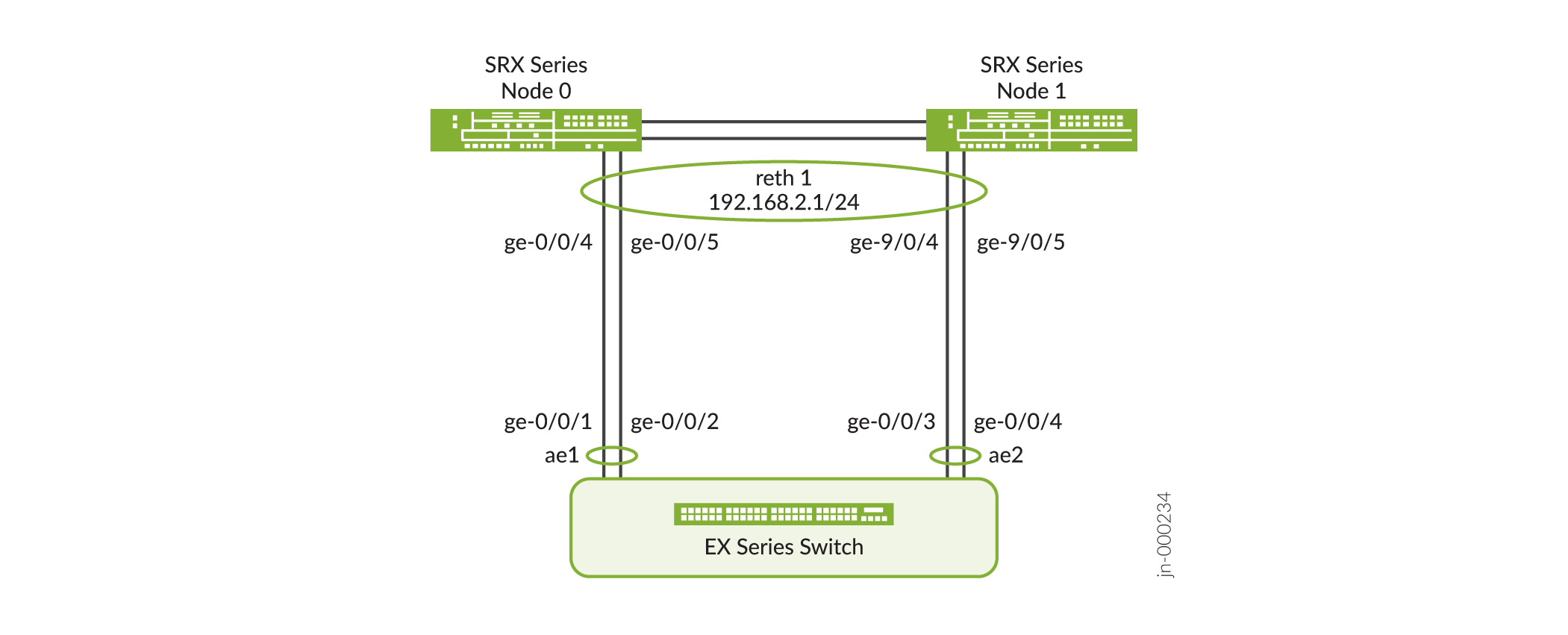
In the Figure 1, SRX1500 devices are used to configure the interfaces on node0 and node1. For more information on EX Series switch configuration, see Configuring Aggregated Ethernet LACP (CLI Procedure).
Configuration
Configure LACP on Chassis Cluster
Step-by-Step Procedure
To configure LACP on chassis clusters:
-
Specify the number of redundant Ethernet interfaces.
[edit chassis cluster]
user@host# set reth-count 2
-
Specify a redundancy group's priority for primacy on each node of the cluster. The higher number takes precedence.
[edit chassis cluster]
user@host# set redundancy-group 1 node 0 priority 200
user@host# set redundancy-group 1 node 1 priority 100
-
Create security zone and assign interfaces to zone.
[edit security zones]
user@host# set security-zone trust host-inbound-traffic system-services all
user@host# set security-zone trust interfaces reth1.0
-
Bind redundant child physical interfaces to reth1.
[edit interfaces]
user@host# set ge-0/0/4 gigether-options redundant-parent reth1
user@host# set ge-0/0/5 gigether-options redundant-parent reth1
user@host# set ge-9/0/4 gigether-options redundant-parent reth1
user@host# set ge-9/0/5 gigether-options redundant-parent reth1
-
Add reth1 to redundancy group 1.
[edit interfaces]
user@host# set reth1 redundant-ether-options redundancy-group 1
-
Set the LACP on reth1.
[edit interfaces]
user@host# set reth1 redundant-ether-options lacp active
user@host# set reth1 redundant-ether-options lacp periodic slow
-
Assign an IP address to reth1.
[edit interfaces]
user@host# set reth1 unit 0 family inet address 192.168.2.1/24
-
Configure LACP on aggregated Ethernet interfaces (ae1).
-
Configure LACP on aggregated Ethernet interfaces (ae2).
-
If you are done configuring the device, commit the configuration.
[edit interfaces]
user@host# commit
Results
From configuration mode, confirm your configuration
by entering the show chassis, show security zones, and show interfaces commands. If the output does not
display the intended configuration, repeat the configuration instructions
in this example to correct it.
[edit]user@host#show chassis cluster { reth-count 2; redundancy-group 1 { node 0 priority 200; node 1 priority 100; } } [edit]user@host#show security zones security-zone trust { host-inbound-traffic { system-services { all; } } interfaces { reth1.0; } } [edit]user@host#show interfaces reth1 { redundant-ether-options { redundancy-group 1; lacp { active; periodic slow; } } unit 0 { family inet { address 192.168.2.1/24; } } }
Configure LACP on EX Series Switch
Step-by-Step Procedure
Configure LACP on EX Series switch.
-
Set the number of aggregated Ethernet interfaces.
[edit chassis]
user@host# set aggregated-devices ethernet device-count 3
-
Associate physical interfaces with aggregated Ethernet interfaces.
[edit interfaces]
user@host# set ge-0/0/1 gigether-options 802.3ad ae1
user@host# set ge-0/0/2 gigether-options 802.3ad ae1
user@host# set ge-0/0/3 gigether-options 802.3ad ae2
user@host# set ge-0/0/4 gigether-options 802.3ad ae2
-
Configure LACP on aggregated Ethernet interfaces (ae1).
[edit interfaces]
user@host# set interfaces ae1 unit 0 family ethernet-switching interface-mode access

user@host# set interfaces ae1 unit 0 family ethernet-switching vlan members RETH0_VLAN
-
Configure LACP on aggregated Ethernet interfaces (ae2).
[edit interfaces]

user@host# set interfaces ae2 unit 0 family ethernet-switching interface-mode access

user@host# set interfaces ae2 unit 0 family ethernet-switching vlan members RETH0_VLAN
-
Configure VLAN.
user@host#set vlans RETH0_VLAN vlan-id 10
user@host# set vlans RETH0_VLAN l3-interface vlan.10
user@host# set interfaces vlan unit 10 family inet address 192.168.2.254/24
Results
From configuration mode, confirm your configuration
by entering the show chassis and show interfaces commands. If the output does not display the intended configuration,
repeat the configuration instructions in this example to correct it.
[edit]user@host#show chassis aggregated-devices { ethernet { device-count 3; } }user@host#show vlans RETH0_VLAN { vlan-id 10; l3-interface vlan.10; }user@host>show vlans RETH0_VLAN Routing instance VLAN name Tag Interfaces default-switch RETH0_VLAN 10 ae1.0* ae2.0*user@host>show ethernet-switching interface ae1 Routing Instance Name : default-switch Logical Interface flags (DL - disable learning, AD - packet action drop, LH - MAC limit hit, DN - interface down, MMAS - Mac-move action shutdown, SCTL - shutdown by Storm-control ) Logical Vlan TAG MAC STP Logical Tagging interface members limit state interface flags ae1.0 131072 untagged RETH0_VLAN 10 131072 Forwarding untaggeduser@host>show ethernet-switching interface ae2 Routing Instance Name : default-switch Logical Interface flags (DL - disable learning, AD - packet action drop, LH - MAC limit hit, DN - interface down, MMAS - Mac-move action shutdown, SCTL - shutdown by Storm-control ) Logical Vlan TAG MAC STP Logical Tagging interface members limit state interface flags ae2.0 131072 untagged RETH0_VLAN 10 131072 Forwarding untaggeduser@host#show interfaces ge-0/0/1 { ether-options { 802.3ad ae1; } } ge-0/0/2 { ether-options { 802.3ad ae1; } } ge-0/0/3 { ether-options { 802.3ad ae2; } } ge-0/0/4 { ether-options { 802.3ad ae2; } } ae1 { aggregated-ether-options { lacp { active; periodic slow; } } unit 0 { family ethernet-switching { interface-mode access; vlan { members RETH0_VLAN; } } } } ae2 { aggregated-ether-options { lacp { active; periodic slow; } } unit 0 { family ethernet-switching { interface-mode access; vlan { members RETH0_VLAN; } } } } vlan { unit 10 { family inet { address 192.168.2.254/24 { } } } }
Verification
Verify LACP on Redundant Ethernet Interfaces
Purpose
Display LACP status information for redundant Ethernet interfaces.
Action
From operational mode, enter the show chassis
cluster status command.
{primary:node0}[edit]
user@host> show chassis cluster status
Monitor Failure codes:
    CS  Cold Sync monitoring        FL  Fabric Connection monitoring
    GR  GRES monitoring             HW  Hardware monitoring
    IF  Interface monitoring        IP  IP monitoring
    LB  Loopback monitoring         MB  Mbuf monitoring
    NH  Nexthop monitoring          NP  NPC monitoring
    SP  SPU monitoring              SM  Schedule monitoring
    CF  Config Sync monitoring      RE  Relinquish monitoring
    IS  IRQ storm

Cluster ID: 1
Node   Priority Status               Preempt Manual   Monitor-failures

Redundancy group: 0 , Failover count: 1
node0  1        primary              no      no       None
node1  1        secondary            no      no       None

Redundancy group: 1 , Failover count: 1
node0  200      primary              no      no       None
node1 100 secondary no no None{primary:node0}[edit]
user@host> show chassis cluster interfaces
Control link status: Up
Control interfaces:
Index Interface Monitored-Status Internal-SA Security
0 fxp1 Up Disabled Disabled
Fabric link status: Up
Fabric interfaces:
Name Child-interface Status Security
(Physical/Monitored)
fab0 ge-0/0/2 Up / Up Enabled
fab0
fab1 ge-9/0/2 Up / Up Enabled
fab1
Redundant-ethernet Information:
Name Status Redundancy-group
reth0 Down Not configured
reth1 Up 1
Redundant-pseudo-interface Information:
Name Status Redundancy-group
lo0 Up 0 From operational mode, enter the show lacp interfaces
reth1 command.
{primary:node0}[edit]
user@host> show lacp interfaces reth1
Aggregated interface: reth1
    LACP state:       Role   Exp   Def  Dist  Col  Syn  Aggr  Timeout  Activity
      ge-0/0/4       Actor    No    No   Yes  Yes  Yes   Yes     Slow    Active
      ge-0/0/4     Partner    No    No   Yes  Yes  Yes   Yes     Slow    Active
      ge-0/0/5       Actor    No    No   Yes  Yes  Yes   Yes     Slow    Active
      ge-0/0/5     Partner    No    No   Yes  Yes  Yes   Yes     Slow    Active
      ge-9/0/4       Actor    No    No   Yes  Yes  Yes   Yes     Slow    Active
      ge-9/0/4     Partner    No    No   Yes  Yes  Yes   Yes     Slow    Active
      ge-9/0/5       Actor    No    No   Yes  Yes  Yes   Yes     Slow    Active
      ge-9/0/5     Partner    No    No   Yes  Yes  Yes   Yes     Slow    Active
    LACP protocol:        Receive State  Transmit State          Mux State
      ge-0/0/4                  Current   Slow periodic Collecting distributing
      ge-0/0/5                  Current   Slow periodic Collecting distributing
      ge-9/0/4                  Current   Slow periodic Collecting distributing
      ge-9/0/5                  Current   Slow periodic Collecting distributing
The output shows redundant Ethernet interface details, including the following information:
-
LACP state—Indicates whether a link in the bundle is acting an the actor (local or near end) or the partner (remote or far end).
-
LACP mode—Indicates whether link aggregation is enabled on both ends of the aggregated Ethernet interface (active or passive). At least one end of the bundle must be configured as active.
-
PDU transmission interval—Shows the periodic rate at which Link Aggregation Control Protocol (LACP) PDUs are transmitted.
-
LACP protocol state—Indicates that the link is operational when it is in the collecting and distributing state.
Example: Configure Chassis Cluster Minimum Links
This example shows how to configure the minimum number of physical links on the primary node that must be operational for a redundant Ethernet interface to remain up.
Requirements
Before you begin:
Configure redundant Ethernet interfaces. See Example: Configuring Chassis Cluster Redundant Ethernet Interfaces.
Understand redundant Ethernet interface link aggregation groups. See Example: Configuring Link Aggregation Groups in a Chassis Cluster.
Overview
When a redundant Ethernet interface includes more than two child links, you can configure a minimum number of physical links on the primary node that must be operational for the interface to remain up. If the number of active physical links on the primary node falls below the configured minimum-links value, the interface transitions to a down state, even if some child links are still operational.
In this example, the minimum-links value for reth1 is set to 3, meaning that at least three child links on the primary node must be operational to keep the interface up. For instance, in a configuration where six interfaces are assigned to reth1, setting the minimum-links to 3 requires all three child links on the primary node to be operational to prevent the interface from going down.
Although it is possible to configure a minimum-links value for a redundant Ethernet interface with only two child interfaces (one per node), this configuration is not recommended.
Configuration
Procedure
Step-by-Step Procedure
To specify the minimum number of links:
Specify the minimum number of links for the redundant Ethernet interface.
{primary:node0}[edit]
user@host# set interfaces reth1 redundant-ether-options minimum-links 3
If you are done configuring the device, commit the configuration.
{primary:node0}[edit]
user@host# commit
Verification
Verify the Chassis Cluster Minimum Links Configuration
Purpose
To verify the configuration is working properly, enter
the show interface reth1 command.
Action
From operational mode, enter the show show interfaces reth1 command.
{primary:node0}[edit]user@host> show interfaces reth1Physical interface: reth1, Enabled, Physical link is Down Interface index: 129, SNMP ifIndex: 548 Link-level type: Ethernet, MTU: 1514, Speed: Unspecified, BPDU Error: None, MAC-REWRITE Error: None, Loopback: Disabled, Source filtering: Disabled, Flow control: Disabled, Minimum links needed: 3, Minimum bandwidth needed: 0 Device flags : Present Running Interface flags: Hardware-Down SNMP-Traps Internal: 0x0 Current address: 00:10:db:ff:10:01, Hardware address: 00:10:db:ff:10:01 Last flapped : 2010-09-15 15:54:53 UTC (1w0d 22:07 ago) Input rate : 0 bps (0 pps) Output rate : 0 bps (0 pps) Logical interface reth1.0 (Index 68) (SNMP ifIndex 550) Flags: Hardware-Down Device-Down SNMP-Traps 0x0 Encapsulation: ENET2 Statistics Packets pps Bytes bps Bundle: Input : 0 0 0 0 Output: 0 0 0 0 Security: Zone: untrust Allowed host-inbound traffic : bootp bfd bgp dns dvmrp igmp ldp msdp nhrp ospf pgm pim rip router-discovery rsvp sap vrrp dhcp finger ftp tftp ident-reset http https ike netconf ping reverse-telnet reverse-ssh rlogin rpm rsh snmp snmp-trap ssh telnet traceroute xnm-clear-text xnm-ssl lsping ntp sip Protocol inet, MTU: 1500 Flags: Sendbcast-pkt-to-re
Example: Configure Redundant Ethernet Interface Link Aggregation Groups on Firewalls with IOC2 or IOC3
Support for IEEE 802.3ad–based Ethernet link aggregation groups (LAGs) allows physical interfaces on a standalone device to be aggregated, providing increased bandwidth and link availability. In a chassis cluster, link aggregation enables a redundant Ethernet interface to include more than two physical child interface, forming a redundant Ethernet interface LAG.
Requirements
This example uses the following software and hardware components:
Junos OS Release 18.2R1 or later for Firewalls.
SRX5800 with IOC2 or IOC3 with Express Path enabled on IOC2 and IOC3. For details, see Example: Configuring SRX5K-MPC3-100G10G (IOC3) and SRX5K-MPC3-40G10G (IOC3) on an SRX5000 Line Device to Support Express Path.
Overview
This example shows how to configure a redundant Ethernet interface link aggregation group and configure LACP on chassis cluster on Firewalls using the ports from either IOC2 or IOC3 in Express Path mode. Note that configuring child interfaces by mixing links from both IOC2 and IOC3 is not supported.
A redundant Ethernet interface or aggregated Ethernet interface (aex) must contain child interfaces from the same IOC type for IOC2 and IOC3. For example, if one child link is from 10-Gigabit Ethernet on IOC2, the second child link should also be from IOC2. This limitation is not applicable for IOC3 and IOC4 child interfaces if the child interfaces have the same speed.
The following combination is not supported:
- Node 0-100GbE from IOC2 and 10GbE/40GbE/100GbE from IOC3
- Node 1-100GbE from IOC2 and 10GbE/40GbE/100GbE from IOC3
The following combination is supported (with the same interface speed):
- Node 0-100GbE from IOC3 and 100GbE from IOC4
- Node 1-100GbE from IOC3 and 100GbE from IOC4
The following member links are used in this example:
-
xe-1/0/0
-
xe-3/0/0
-
xe-14/0/0
-
xe-16/0/0
Configuration
CLI Quick Configuration
To quickly configure this example, copy the
following commands, paste them into a text file, remove any line breaks,
change any details necessary to match your network configuration,
delete, and then copy and paste the commands into the CLI at the [edit] hierarchy level, and then enter commit from
configuration mode.
set chassis cluster reth-count 5
set interfaces reth0 redundant-ether-options redundancy-group 1
set interfaces reth0 redundant-ether-options lacp active
set interfaces reth0 redundant-ether-options lacp periodic fast
set interfaces reth0 redundant-ether-options minimum-links 1
set interfaces reth0 unit 0 family inet address 192.0.2.1/24
set interfaces xe-1/0/0 gigether-options redundant-parent reth0
set interfaces xe-3/0/0 gigether-options redundant-parent reth0
set interfaces xe-14/0/0 gigether-options redundant-parent reth0
set interfaces xe-16/0/0 gigether-options redundant-parent reth0
Procedure
Step-by-Step Procedure
To configure LAG Interfaces:
Specify the number of aggregated Ethernet interfaces to be created.
[edit chassis]
user@host# set chassis cluster reth-count 5
Bind redundant child physical interfaces to reth0.
[edit interfaces]
user@host# set xe-1/0/0 gigether-options redundant-parent reth0
user@host# set xe-3/0/0 gigether-options redundant-parent reth0
user@host# set xe-14/0/0 gigether-options redundant-parent reth0
user@host# set xe-16/0/0 gigether-options redundant-parent reth0
Add reth0 to redundancy group 1.
user@host#set reth0 redundant-ether-options redundancy-group 1
Assign an IP address to reth0.
[edit interfaces]
user@host# set reth0 unit 0 family inet address 192.0.2.1/24
Set the LACP on reth0.
[edit interfaces]
user@host# set reth0 redundant-ether-options lacp active
user@host# set reth0 redundant-ether-options lacp periodic fast
user@host# set reth0 redundant-ether-options minimum-links 1
Results
From configuration mode, confirm your configuration
by entering the show interfaces command. If the output
does not display the intended configuration, repeat the configuration
instructions in this example to correct it.
[edit]
user@host# show interfaces
xe-1/0/0 {
    gigether-options {
        redundant-parent reth0;
    }
}
xe-3/0/0 {
    gigether-options {
        redundant-parent reth0;
    }
}
xe-14/0/0 {
    gigether-options {
        redundant-parent reth0;
    }
}
xe-16/0/0 {
    gigether-options {
        redundant-parent reth0;
    }
}
reth0 {
    redundant-ether-options {
        lacp {
            active;
            periodic fast;
        }
        minimum-links 1;
    }
    unit 0 {
        family inet {
            address 192.0.2.1/24;
        }
    }
}
ae1 {
    aggregated-ether-options {
        lacp {
            active;
        }
    }
    unit 0 {
        family inet {
            address 192.0.2.2/24;
        }
    }
}
[edit]
user@host# show chassis
chassis cluster {
    reth-count 5;
}
If you are done configuring the device, enter commit from configuration mode.
Verification
Verify LACP on Redundant Ethernet Interfaces
Purpose
Display LACP status information for redundant Ethernet interfaces.
Action
From operational mode, enter the show lacp interfaces command to check that LACP has been enabled as active on one end.
user@host> show lacp interfaces

Aggregated interface: reth0
    LACP state:       Role   Exp   Def  Dist  Col  Syn  Aggr  Timeout  Activity
      xe-16/0/0      Actor    No    No   Yes  Yes  Yes   Yes     Fast    Active
      xe-16/0/0    Partner    No    No   Yes  Yes  Yes   Yes     Fast    Active
      xe-14/0/0      Actor    No    No   Yes  Yes  Yes   Yes     Fast    Active
      xe-14/0/0    Partner    No    No   Yes  Yes  Yes   Yes     Fast    Active
      xe-1/0/0       Actor    No    No   Yes  Yes  Yes   Yes     Fast    Active
      xe-1/0/0     Partner    No    No   Yes  Yes  Yes   Yes     Fast    Active
      xe-3/0/0       Actor    No    No   Yes  Yes  Yes   Yes     Fast    Active
      xe-3/0/0     Partner    No    No   Yes  Yes  Yes   Yes     Fast    Active
    LACP protocol:        Receive State  Transmit State          Mux State
      xe-16/0/0                 Current   Fast periodic Collecting distributing
      xe-14/0/0                 Current   Fast periodic Collecting distributing
      xe-1/0/0                  Current   Slow periodic Collecting distributing
      xe-3/0/0                  Current   Slow periodic Collecting distributing
The output indicates that LACP has been set up correctly and is active at one end.
Understand VRRP on SRX Series Firewalls
Firewalls support the Virtual Router Redundancy Protocol (VRRP) and VRRP for IPv6.
- Overview of VRRP on SRX Series Firewalls
- Benefits of VRRP
- Sample VRRP Topology
- Firewalls Support for VRRPv3
- Limitations of VRRPv3 Features
Overview of VRRP on SRX Series Firewalls
Configuring end hosts with static default routes simplifies network configuration, reduces complexity, and minimizes processing overhead on the hosts. However, if the default gateway fails, hosts that cannot detect alternate paths become isolated. VRRP addresses this limitation by providing dynamic default gateway redundancy. If the primary gateway fails, VRRP enables an alternate gateway to take over automatically.
You can configure VRRP and VRRP for IPv6 on Gigabit Ethernet interfaces, 10-Gigabit Ethernet interfaces, and logical interfaces on Firewalls. VRRP allows hosts on a LAN to use redundant gateway devices without requiring more than a single static default route configuration.
Devices participating in VRRP share a virtual IP address that corresponds to the default gateway configured on the hosts. At any given time, one device acts as the primary (active) router, while the others function as backups. If the primary device fails, one of the backup devices assumes the primary role, maintaining uninterrupted traffic forwarding on the LAN. With VRRP, a backup Firewall can take over a failed default gateway within a few seconds, with minimal traffic distribution and no interaction required from the hosts. VRRP is not supported on management interfaces.
VRRP for IPv6 provides faster switchover to an alternate default gateway than IPv6
Neighbor Discovery (ND) mechanisms. VRRP for IPv6 does not support the
authentication-type or authentication-key
statements.
Devices running VRRP dynamically elect primary and backup routers. You can also explicitly control this behavior by assigning priorities from 1 through 255, where 255 is the highest priority. During normal operation, the primary device sends VRRP advertisements to backup devices at regular intervals; the default interval is 1 second. If a backup device does not receive advertisement for a specified period, the backup device with the highest priority assumes the primary role and begins forwarding traffic.
Backup devices do not preempt the primary device unless they have a higher priority, which helps prevent unnecessary service disruption. You can also administratively disable all preemption attempts, except when a VRRP device becomes primary for IP addresses that it owns.
VRRP does not support session synchronization between members. If the primary device fails, the backup device with the highest priority takes over and begins forwarding packets, but any existing sessions are dropped because they are out of state.
Priority 255 cannot be configured on routed VLAN interfaces (RVIs).
VRRP is defined in RFC 3768, Virtual Router Redundancy Protocol.
Benefits of VRRP
-
VRRP provides dynamic failover of IP addresses from one device to another in the event of failure.
-
You can implement VRRP to provide a highly available default path to a gateway without needing to configure dynamic routing or router discovery protocols on end hosts.
Sample VRRP Topology
Figure 2 illustrates a basic VRRP topology with SRX Series Firewalls. In this example, Devices A and B are running VRRP and share the virtual IP address 192.0.2.1. The default gateway for each of the clients is 192.0.2.1.
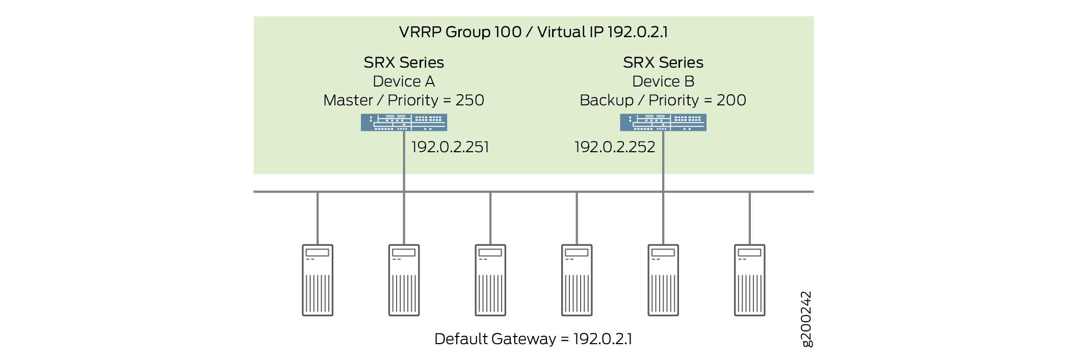
The following illustrates basic VRRP behavior using Figure 2 for reference:
-
When any of the servers wants to send traffic out of the LAN, it sends the traffic to the default gateway address of 192.0.2.1. This is a virtual IP address (VIP) owned by VRRP group 100. Because Device A is the primary of the group, the VIP is associated with the “real” address 192.0.2.251 on Device A, and traffic from the servers is actually sent to this address. (Device A is the primary because it has been configured with a higher priority value.)
-
If there is a failure on Device A that prevents it from forwarding traffic to or from the servers—for example, if the interface connected to the LAN fails—Device B becomes the primary and assumes ownership of the VIP. The servers continue to send traffic to the VIP, but because the VIP is now associated with the “real” address 192.0.2.252 on Device B (because of change of primary), the traffic is sent to Device B instead of Device A.
-
If the problem that caused the failure on Device A is corrected, Device A becomes the primary again and reasserts ownership of the VIP. In this case, the servers resume sending traffic to Device A.
Note that no configuration changes are required on the servers to switch traffic between Device A and Device B. When the VIP moves between 192.0.2.251 and 192.0.2.252, the transition is handled automatically by standard TCP/IP behavior, requiring no server-side configuration or manual intervention.
Firewalls Support for VRRPv3
The primary advantage of using VRRPv3 is that it supports both IPv4 and IPv6 address families, whereas earlier versions of VRRP supports only IPv4.
Enable VRRPv3 only if it can be enabled on all devices in the network that participate in VRRP. VRRPv3 for IPv4 does not interoperate with earlier VRRP versions. For example, if a device VRRPv3 enabled receives VRRP IPv4 advertisement packets from a device running an earlier VRRP version, it transitions to the backup state to prevent the creation of multiple primary routers in the network.
You can enable VRRPv3 by configuring the version-3 statement at the [edit
protocols vrrp] hierarchy level for either IPv4 or IPv6 networks. Ensure
that the same VRRP version is configured on all VRRP devices on the LAN.
Limitations of VRRPv3 Features
Below are some VRRPv3 features limitations.
VRRPv3 Authentication
When VRRPv3 (for IPv4) is enabled, it does not allow authentication.
-
The
authentication-typeandauthentication-keystatements cannot be configured for any VRRP groups. -
You must use non-VRRP authentication.
VRRPv3 Advertisement Intervals
VRRPv3 (for IPv4 and IPv6) advertisement intervals must be set with the fast-interval statement at the [edit interfaces interface-name unit 0 family inet address ip-address vrrp-group group-name] hierarchy level.
-
Do not use the
advertise-intervalstatement (for IPv4). -
Do not use the
inet6-advertise-intervalstatement (for IPv6).
See Also
VRRP failover-delay Overview
Failover is a backup operational mode in which the functions of a network device are assumed by a secondary device when the primary device becomes unavailable because of a failure or a scheduled down time. Failover is typically an integral part of mission-critical systems that must be constantly available on the network.
VRRP does not support session synchronization between members. If the primary device fails, the backup device with the highest priority takes over as primary and will begin forwarding packets. Any existing sessions will be dropped on the backup device as out-of-state.
A fast failover requires a short delay. Thus, failover-delay configures the failover delay time, in milliseconds, for VRRP and VRRP for IPv6 operations. Junos OS supports a range of 50 through 100000 milliseconds for delay in failover time.
The VRRP process (vrrpd) running on the Routing Engine communicates a VRRP primary role change to the Packet Forwarding Engine for every VRRP session. Each VRRP group can trigger such communication to update the Packet Forwarding Engine with its own state or the state inherited form an active VRRP group. To avoid overloading the Packet Forwarding Engine with such messages, you can configure a failover-delay to specify the delay between subsequent Routing Engine to Packet Forwarding Engine communications.
The Routing Engine communicates a VRRP primary role change to the Packet Forwarding Engine to facilitate necessary state change on the Packet Forwarding Engine, such as reprogramming of Packet Forwarding Engine hardware filters, VRRP sessions and so on. The following sections elaborate the Routing Engine to Packet Forwarding Engine communication in two scenarios:
When failover-delay Is Not Configured
Without failover-delay configured, the sequence of events for VRRP sessions operated from the Routing Engine is as follows:
When the first VRRP group detected by the Routing Engine changes state, and the new state is primary, the Routing Engine generates appropriate VRRP announcement messages. The Packet Forwarding Engine is informed about the state change, so that hardware filters for that group are reprogrammed without delay. The new primary then sends gratuitous ARP message to the VRRP groups.
The delay in failover timer starts. By default, failover-delay timer is:
500 miliseconds—when the configured VRRP announcement interval is less than 1 second.
2 seconds—when the configured VRRP announcement interval is 1 second or more, and the total number of VRRP groups on the router is 255.
10 seconds—when the configured VRRP announcement interval is 1 second or more, and the number of VRRP groups on the router is more than 255.
The Routing Engine performs one-by-one state change for subsequent VRRP groups. Every time there is a state change, and the new state for a particular VRRP group is primary, the Routing Engine generates appropriate VRRP announcement messages. However, communication toward the Packet Forwarding Engine is suppressed until the failover-delay timer expires.
After failover-delay timer expires, the Routing Engine sends message to the Packet Forwarding Engine about all VRRP groups that managed to change the state. As a consequence, hardware filters for those groups are reprogrammed, and for those groups whose new state is primary, gratuitous ARP messages are sent.
This process repeats until state transition for all VRRP groups is complete.
Thus, without configuring failover-delay, the full state transition (including states on the Routing Engine and the Packet Forwarding Engine) for the first VRRP group is performed immediately, while state transition on the Packet Forwarding Engine for remaining VRRP groups is delayed by at least 0.5-10 seconds, depending on the configured VRRP announcement timers and the number of VRRP groups. During this intermediate state, receiving traffic for VRRP groups for state changes that were not yet completed on the Packet Forwarding Engine might be dropped at the Packet Forwarding Engine level due to deferred reconfiguration of hardware filters.
When failover-delay Is Configured
When failover-delay is configured, the sequence of events for VRRP sessions operated from the Routing Engine is modified as follows:
The Routing Engine detects that some VRRP groups require a state change.
The failover-delay starts for the period configured. The allowed failover-delay timer range is 50 through 100000 miliseconds.
The Routing Engine performs one-by-one state change for the VRRP groups. Every time there is a state change, and the new state for a particular VRRP group is primary, the Routing Engine generates appropriate VRRP announcement messages. However, communication toward the Packet Forwarding Engine is suppressed until the failover-delay timer expires.
After failover-delay timer expires, the Routing Engine sends message to the Packet Forwarding Engine about all VRRP groups that managed to change the state. As a consequence, hardware filters for those groups are reprogrammed, and for those groups whose new state is primary, gratuitous ARP messages are sent.
This process repeats until state transition for all VRRP groups is complete.
Thus, when failover-delay is configured even the Packet Forwarding Engine state for the first VRRP group is deferred. However, the network operator has the advantage of configuring a failover-delay value that best suits the need of the network deployment to ensure minimal outage during VRRP state change.
failover-delay influences only VRRP sessions operated by the VRRP process (vrrpd) running on the Routing Engine. For VRRP sessions distributed to the Packet Forwarding Engine, failover-delay configuration has no effect.
Example: Configure VRRP/VRRPv3 on Chassis Cluster Redundant Ethernet Interfaces
When Virtual Router Redundancy Protocol (VRRP) is configured, multiple devices are grouped into a single virtual router. At any given time, one device operates as the primary (active) router, while the remaining devices function as backups. If the primary device fails, one of the backup devices assumes the primary device.
This example describes how to configure VRRP on a redundant Ethernet interface:
Requirements
This example uses the following hardware and software components:
-
Junos OS Release 18.1 R1 or later for Firewalls.
-
Two Firewalls connected in a chassis cluster.
-
One Firewall connected as standalone device.
Overview
You configure VRRP by creating VRRP groups on redundant Ethernet interfaces on chassis cluster devices and on Gigabit Ethernet interface on standalone devices. A redundant Ethernet interface on a chassis cluster device or a Gigabit Ethernet interface on a standalone device can participate in one or more VRRP groups. Within a VRRP group, the primary redundant Ethernet interface on the chassis cluster device and the backup Gigabit Ethernet interface on the standalone device must be configured.
To configure a VRRP group, you must specify a group identifier and a virtual IP address on all member interfaces. The virtual IP address must be identical across all interfaces in the VRRP group. You then assign priorities to the redundant Ethernet and Gigabit Ethernet interfaces to determine which interface becomes the primary.
You can explicitly control primary and backup roles by configuring priorities from 1 through 255, where 255 represents the highest priority.
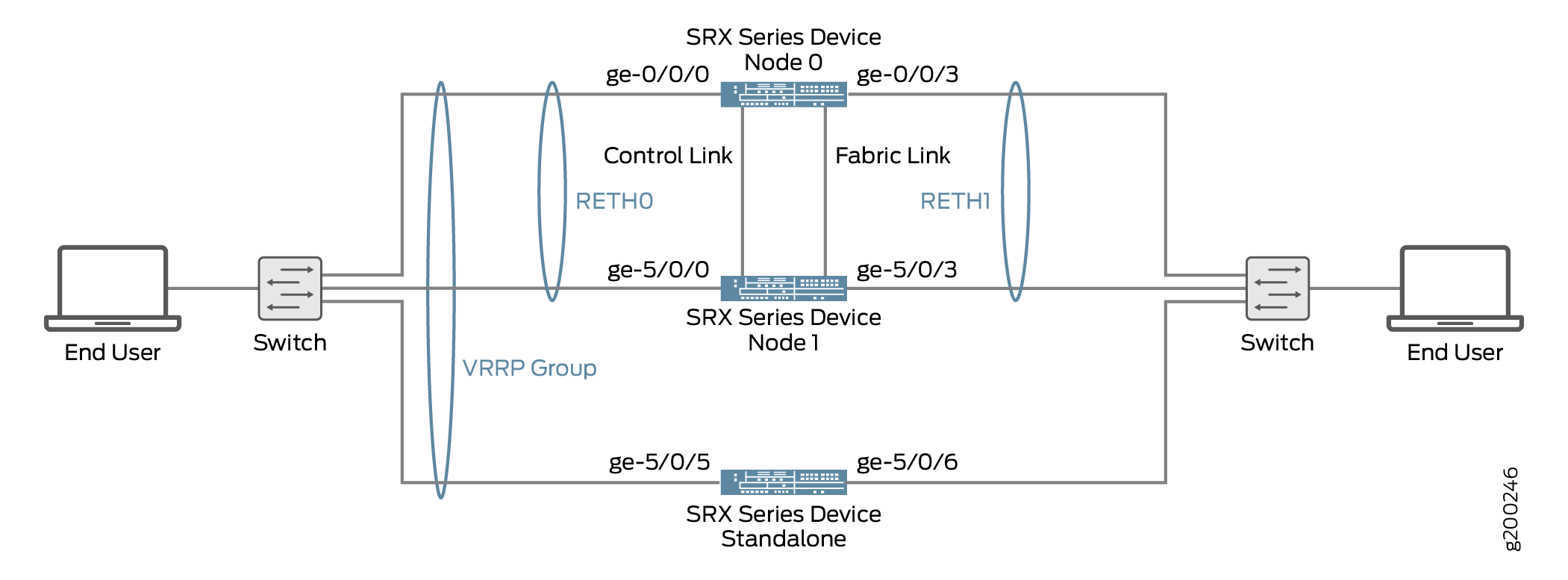
Configuration VRRP
- Configure VRRPv3, VRRP Groups, and Priority on Redundant Ethernet Interfaces
- Configuring VRRP Groups on Standalone Device
Configure VRRPv3, VRRP Groups, and Priority on Redundant Ethernet Interfaces
CLI Quick Configuration
To quickly configure this example, copy the
following commands, paste them into a text file, remove any line breaks,
change any details necessary to match your network configuration,
copy and paste the commands into the CLI at the [edit] hierarchy level, and then enter commit from configuration
mode.
set protocols vrrp traceoptions file vrrp.logset protocols vrrp traceoptions file size 10000000set protocols vrrp traceoptions flag allset protocols vrrp version-3set protocols vrrp ignore-nonstop-routingset interfaces ge-0/0/0 gigether-options redundant-parent reth0set interfaces ge-0/0/3 gigether-options redundant-parent reth1set interfaces ge-5/0/0 gigether-options redundant-parent reth0set interfaces ge-5/0/3 gigether-options redundant-parent reth1set interfaces reth0 redundant-ether-options redundancy-group 1set interfaces reth0 unit 0 family inet address 192.0.2.2/24 vrrp-group 0 virtual-address 192.0.2.3set interfaces reth0 unit 0 family inet address 192.0.2.2/24 vrrp-group 0 priority 255set interfaces reth0 unit 0 family inet address 192.0.2.2/24 vrrp-group 0 accept-dataset interfaces reth0 unit 0 family inet6 address 2001:db8::2/32 vrrp-inet6-group 2 virtual-inet6-address 2001:db8::3set interfaces reth0 unit 0 family inet6 address 2001:db8::2/32 vrrp-inet6-group 2 priority 255set interfaces reth0 unit 0 family inet6 address 2001:db8::2/32 vrrp-inet6-group 2 accept-dataset interfaces reth1 redundant-ether-options redundancy-group 2set interfaces reth1 unit 0 family inet address 192.0.2.4/24 vrrp-group 1 virtual-address 192.168.120.3set interfaces reth1 unit 0 family inet address 192.0.2.4/24 vrrp-group 1 priority 150set interfaces reth1 unit 0 family inet address 192.0.2.4/24 vrrp-group 1 accept-dataset interfaces reth1 unit 0 family inet6 address 2001:db8::3/32 vrrp-inet6-group 3 virtual-inet6-address 2001:db8::4set interfaces reth1 unit 0 family inet6 address 2001:db8::3/32 vrrp-inet6-group 3 priority 150set interfaces reth1 unit 0 family inet6 address 2001:db8::3/32 vrrp-inet6-group 3 accept-data
Step-by-Step Procedure
To configure VRRPv3, VRRP Groups, and priority on chassis cluster devices:
-
Configure a filename to the traceoptions to trace VRRP protocol traffic.
[edit protocols vrrp] user@host#
set traceoptions file vrrp.log -
Specify the maximum trace file size.
[edit protocols vrrp] user@host#
set traceoptions file size 10000000 -
Enable vrrp traceoptions.
[edit protocols vrrp] user@host#
set traceoptions flag all -
Set vrrp version to 3.
[edit protocols vrrp] user@host#
set version-3 -
Configure this command to support graceful Routing Engine switchover (GRES) for VRRP and for nonstop active routing when there is VRRP reth failover. Using vrrp, a secondary node can take over a failed primary node within a few seconds and this is done with minimum VRRP traffic and without any interaction with the hosts
[edit protocols vrrp] user@host#
set ignore-nonstop-routing -
Set up the redundant Ethernet (reth) interfaces and assign the redundant interface to a zone.
[edit interfaces] user@host#
set ge-0/0/0 gigether-options redundant-parent reth0user@host#set ge-0/0/3 gigether-options redundant-parent reth1user@host#set ge-5/0/0 gigether-options redundant-parent reth0user@host#set ge-5/0/3 gigether-options redundant-parent reth1user@host#set reth0 redundant-ether-options redundancy-group 1user@host#set reth1 redundant-ether-options redundancy-group 2 -
Configure the family inet address and virtual address for the redundant interface 0 unit 0.
[edit interfaces] user@host#
set reth0 unit 0 family inet address 192.0.2.2/24 vrrp-group 0 virtual-address 192.168.110.3user@host#set reth0 unit 0 family inet6 address 2001:db8::2/32 vrrp-inet6-group 2 virtual-inet6-address 2001:db8::3 -
Configure the family inet address and virtual address for the redundant interface 1 unit 0.
[edit interfaces] user@host#
set reth1 unit 0 family inet address 192.0.2.4/24 vrrp-group 1 virtual-address 192.168.120.3user@host#set reth1 unit 0 family inet6 address 2001:db8::3/32 vrrp-inet6-group 3 virtual-inet6-address 2001:db8::4 -
Set the priority of the redundant interface 0 unit 0 to 255.
[edit interfaces] user@host#
set reth0 unit 0 family inet address 192.0.2.2/24 vrrp-group 0 priority 255user@host#set reth0 unit 0 family inet6 address 2001:db8::2/32 vrrp-inet6-group 2 priority 255 -
Set the priority of the redundant interface 1 unit 0 to 150.
[edit interfaces] user@host#
set reth1 unit 0 family inet address 192.0.2.4/24 vrrp-group 1 priority 150user@host#set reth1 unit 0 family inet6 address 2001:db8::3/32 vrrp-inet6-group 3 priority 150 -
Configure the redundant interface 0 unit 0 to accept all packets sent to the virtual IP address.
[edit interfaces] user@host#
set reth0 unit 0 family inet address 192.0.2.2/24 vrrp-group 0 accept-datauser@host#set reth0 unit 0 family inet6 address 2001:db8::2/32 vrrp-inet6-group 2 accept-data -
Configure the redundant interface 1 unit 0 to accept all packets sent to the virtual IP address.
[edit interfaces] user@host#
set reth1 unit 0 family inet address 192.0.2.4/24 vrrp-group 1 accept-datauser@host#set reth1 unit 0 family inet6 address 2001:db8::3/32 vrrp-inet6-group 3 accept-data
Results
From configuration mode, confirm your configuration
by entering the show interfaces reth0 and show interfaces
reth1 commands. If the output does not display the intended
configuration, repeat the configuration instructions in this example
to correct it.
[edit]
user@host# show interfaces reth0
redundant-ether-options {
    redundancy-group 1;
}
unit 0 {
    family inet {
        address 192.0.2.2/24 {
            vrrp-group 0 {
                virtual-address 192.0.2.3;
                priority 255;
                accept-data;
            }
        }
    }
    family inet6 {
        address 2001:db8::2/32 {
            vrrp-inet6-group 2 {
                virtual-inet6-address 2001:db8::3;
                priority 255;
                accept-data;
            }
        }
    }
}[edit]
user@host# show interfaces reth1
redundant-ether-options {
redundancy-group 2;
}
unit 0 {
family inet {
address 192.0.2.4/24 {
vrrp-group 1 {
virtual-address 192.0.2.5;
priority 150;
accept-data;
}
}
}
family inet6 {
address 2001:db8::3/32 {
vrrp-inet6-group 3 {
virtual-inet6-address 2001:db8::4;
priority 150;
accept-data;
}
}
}
}If you are done configuring the device, enter commit from configuration mode.
Configuring VRRP Groups on Standalone Device
CLI Quick Configuration
To quickly configure this example, copy the
following commands, paste them into a text file, remove any line breaks,
change any details necessary to match your network configuration,
copy and paste the commands into the CLI at the [edit] hierarchy
level, and then enter commit from configuration mode.
set protocols vrrp version-3set interfaces xe-5/0/5 unit 0 family inet address 192.0.2.1/24 vrrp-group 0 virtual-address 192.0.2.3set interfaces xe-5/0/5 unit 0 family inet address 192.0.2.1/24 vrrp-group 0 priority 50set interfaces xe-5/0/5 unit 0 family inet address 192.0.2.1/24 vrrp-group 0 accept-dataset interfaces xe-5/0/5 unit 0 family inet6 address 2001:db8::1/32 vrrp-inet6-group 2 virtual-inet6-address 2001:db8::3set interfaces xe-5/0/5 unit 0 family inet6 address 2001:db8::1/32 vrrp-inet6-group 2 priority 50set interfaces xe-5/0/5 unit 0 family inet6 address 2001:db8::1/32 vrrp-inet6-group 2 accept-dataset interfaces xe-5/0/6 unit 0 family inet address 192.0.2.1/24 vrrp-group 1 virtual-address 192.0.2.5set interfaces xe-5/0/6 unit 0 family inet address 192.0.2.1/24 vrrp-group 1 priority 50set interfaces xe-5/0/6 unit 0 family inet address 192.0.2.1/24 vrrp-group 1 accept-dataset interfaces xe-5/0/6 unit 0 family inet6 address 2001:db8::5/32 vrrp-inet6-group 3 virtual-inet6-address 2001:db8::4set interfaces xe-5/0/6 unit 0 family inet6 address 2001:db8::5/32 vrrp-inet6-group 3 priority 50set interfaces xe-5/0/6 unit 0 family inet6 address 2001:db8::5/32 vrrp-inet6-group 3 accept-data
Step-by-Step Procedure
To configure VRRP groups on standalone device:
-
Set vrrp version to 3.
[edit protocols vrrp] user@host#
set version-3 -
Configure the family inet address and virtual address for the Gigabit Ethernet interface unit 0.
[edit interfaces] user@host#
set xe-5/0/5 unit 0 family inet address 192.0.2.1/24 vrrp-group 0 virtual-address 192.0.2.3user@host#set xe-5/0/5 unit 0 family inet6 address 2001:db8::1/32 vrrp-inet6-group 2 virtual-inet6-address 2001:db8::3user@host#set xe-5/0/6 unit 0 family inet address 192.0.2.1/24 vrrp-group 1 virtual-address 192.0.2.5user@host#set xe-5/0/6 unit 0 family inet6 address 2001:db8::5/32 vrrp-inet6-group 3 virtual-inet6-address 2001:db8::4 -
Set the priority of the Gigabit Ethernet interface unit 0 to 50.
[edit interfaces] user@host#
set xe-5/0/5 unit 0 family inet address 192.0.2.1/24 vrrp-group 0 priority 50user@host#set xe-5/0/5 unit 0 family inet6 address 2001:db8::1/32 vrrp-inet6-group 2 priority 50user@host#set xe-5/0/6 unit 0 family inet address 192.0.2.1/24 vrrp-group 1 priority 50user@host#set xe-5/0/6 unit 0 family inet6 address 2001:db8::5/32 vrrp-inet6-group 3 priority 50 -
Configure the Gigabit Ethernet interface unit 0 to accept all packets sent to the virtual IP address.
[edit interfaces] user@host#
set xe-5/0/5 unit 0 family inet address 192.0.2.1/24 vrrp-group 0 accept-datauser@host#set xe-5/0/5 unit 0 family inet6 address 2001:db8::1/32 vrrp-inet6-group 2 accept-datauser@host#set xe-5/0/6 unit 0 family inet address 192.0.2.1/24 vrrp-group 1 accept-datauser@host#set xe-5/0/6 unit 0 family inet6 address 2001:db8::5/32 vrrp-inet6-group 3 accept-data
Results
From configuration mode, confirm your configuration
by entering the show interfaces xe-5/0/5 and show
interfaces xe-5/0/6 commands. If the output does not display
the intended configuration, repeat the configuration instructions
in this example to correct it.
[edit]
user@host# show interfaces xe-5/0/5
unit 0 {
    family inet {
        address 192.0.2.1/24 {
            vrrp-group 0 {
                virtual-address 192.0.2.3;
                priority 50;
                accept-data;
            }
        }
    }
    family inet6 {
        address 2001:db8::1/32 {
            vrrp-inet6-group 2 {
                virtual-inet6-address 2001:db8::3;
                priority 50;
                accept-data;
            }
        }
    }
} [edit]
user@host# show interfaces xe-5/0/6
unit 0 {
family inet {
address 192.0.2.1/24 {
vrrp-group 1 {
virtual-address 192.0.2.5;
priority 50;
accept-data;
}
}
}
family inet6 {
address 2001:db8::5/32 {
vrrp-inet6-group 3 {
virtual-inet6-address 2001:db8::4;
priority 50;
accept-data;
}
}
}
}If you are done configuring the device, enter commit from configuration mode.
Verification
Confirm that the configuration is working properly.
Verifying the VRRP on Chassis Cluster Devices
Purpose
Verify that VRRP on chassis cluster devices has been configured properly.
Action
From operational mode, enter the show vrrp brief command to display the status of VRRP on chassis cluster devices.
user@host> show vrrp brief
Interface     State       Group   VR state VR Mode   Timer    Type   Address
      reth0.0       up              0   master   Active      A  0.149 lcl    192.0.2.3
    vip    192.0.2.3
    reth0.0       up              2   master   Active      A  0.155 lcl    2001:db8::2
    vip    2001:db8:5eff:fe00:202
    vip    2001:db8::2
    reth1.0       up              1   master   Active      A  0.445 lcl    192.0.2.4
    vip    192.0.2.4
    reth1.0       up              3   master   Active      A  0.414 lcl    2001:db8::4
    vip    2001:db8:5eff:fe00:203
    vip    2001:db8::4
Meaning
The sample output shows that all four VRRP groups are active and that the redundant interfaces has assumed the correct primary roles. The lcl address represents the physical IP address of the interface, while the vip address represents the virtual IP address shared by redundant interfaces.
The Timer values (A 0.149, A 0.155, A 0.445, and A 0.414) indicate the remaining time, in seconds, within which the redundant interfaces expect to receive a VRRP advertisement from the Gigabit Ethernet interfaces. If an advertisement for VRRP groups 0, 1, 2, and 3 is not received before the timer expires, the chassis cluster device declares itself the primary for the corresponding group.
Verify the VRRP on standalone device
Purpose
Verify that VRRP has been configured properly on a standalone device.
Action
From operational mode, enter the show vrrp brief command
to display the status of VRRP on standalone device.
user@host> show vrrp brief
Interface     State       Group   VR state VR Mode   Timer    Type   Address
        xe-5/0/5.0    up              0   backup   Active      D  3.093 lcl    192.0.2.2.1
    vip    192.0.2.2
    mas    192.0.2.2.2
    xe-5/0/5.0    up               2   backup   Active     D  3.502 lcl    2001:db8::2:1
    vip    2001:db8:200:5eff:fe00:202
    vip    2001:db8::2
    mas    2001:db8:210:dbff:feff:1000
    xe-5/0/6.0    up              1   backup   Active      D  3.499 lcl    192.0.2.5.1
    vip    192.0.2.5
    mas    192.0.2.5.2
    xe-5/0/6.0    up              3   backup   Active      D  3.282 lcl    2001:db8::5
    vip    2001:db8:200:5eff:fe00:203
    vip    2001:db8::4
    mas    2001:db8:210:dbff:feff:1001
Meaning
The sample output shows that all four VRRP groups are active and that the Gigabit Ethernet interfaces have assumed the correct backup roles. The lcl address represents the physical interface address, while thevip address represents the virtual IP address shared by the Gigabit Ethernet interfaces. The Timer values (D 3.093, D 3.502, D 3.499, and D 3.282) indicates the remaining time, in seconds, within which the Gigabit Ethernet interfaces expect to receive a VRRP advertisement from the redundant interfaces. If an advertisement for VRRP groups 0, 1, 2, or 3 is not received before the timer expires, the standalone device remains in the backup state.
Example: Configuring VRRP for IPv6
This example shows how to configure VRRP properties for IPv6.
Requirements
This example uses the following hardware and software components:
-
Three routers
-
Junos OS Release 11.3 or later
- This example has been recently updated and revalidated on Junos OS Release 21.1R1.
- For details on VRRP support for specific platform and Junos OS release combinations, see Feature Explorer.
Overview
This example uses a VRRP group, which has a virtual address for IPv6. Devices on the LAN use this virtual address as their default gateway. If the primary router fails, the backup router takes over for it.
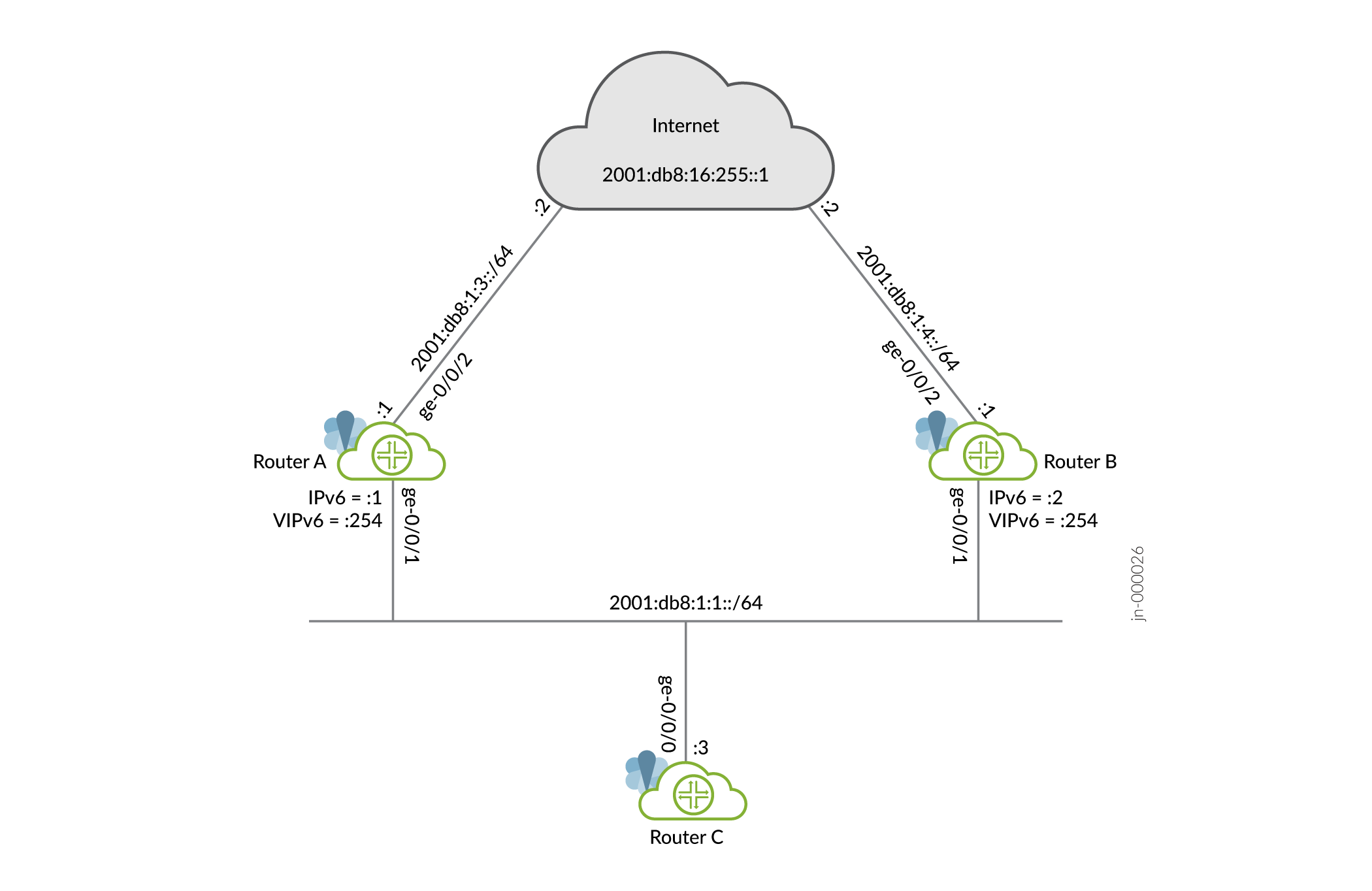
Configuring VRRP
Configuring Router A
CLI Quick Configuration
To quickly configure this example, copy the following commands, paste into a
text file, remove any line breaks, change any details necessary to match
your network configuration, and then copy and paste the commands into the
CLI at the [edit] hierarchy level.
set interfaces ge-0/0/1 unit 0 family inet6 address 2001:db8:1:1::1/64 vrrp-inet6-group 1 virtual-inet6-address 2001:db8:1:1::254
set interfaces ge-0/0/1 unit 0 family inet6 address 2001:db8:1:1::1/64 vrrp-inet6-group 1 priority 110
set interfaces ge-0/0/1 unit 0 family inet6 address 2001:db8:1:1::1/64 vrrp-inet6-group 1 accept-data
set interfaces ge-0/0/1 unit 0 family inet6 address 2001:db8:1:1::1/64 vrrp-inet6-group 1 track interface ge-0/0/2 priority-cost 20
set interfaces ge-0/0/2 unit 0 family inet6 address 2001:db8:1:3::1/64
set protocols router-advertisement interface ge-0/0/1.0 virtual-router-only
set protocols router-advertisement interface ge-0/0/1.0 prefix 2001:db8:1:1::/64
set routing-options rib inet6.0 static route 0::0/0 next-hop 2001:db8:1:3::2
Step-by-Step Procedure
To configure this example:
-
Configure the interfaces.
[edit]
user@routerA# set interfaces ge-0/0/1 unit 0 family inet6 address 2001:db8:1:1::1/64
user@routerA# set interfaces ge-0/0/2 unit 0 family inet6 address 2001:db8:1:3::1/64
-
Configure the IPv6 VRRP group identifier and the virtual IP address.
[edit interfaces ge-0/0/1 unit 0 family inet6 address 2001:db8:1:1::1/64]
user@routerA# set vrrp-inet6-group 1 virtual-inet6-address 2001:db8:1:1::254
-
Configure the priority for RouterA higher than RouterB to become the primary virtual router. RouterB is using the default priority of 100.
[edit interfaces ge-0/0/1 unit 0 family inet6 address 2001:db8:1:1::1/64]
user@routerA# set vrrp-inet6-group 1 priority 110
-
Configure
track interfaceto track whether the interface connected to the Internet is up, down, or not present to change the priority of the VRRP group.[edit interfaces ge-0/0/1 unit 0 family inet6 address 2001:db8:1:1::1/64] user@routerA# set vrrp-inet6-group 1 track interface ge-0/0/2 priority-cost 20
-
Configure
accept-datato enable the primary router to accept all packets destined for the virtual IP address.[edit interfaces ge-0/0/1 unit 0 family inet6 address 2001:db8:1:1::1/64] user@routerA# set vrrp-inet6-group 1 accept-data
-
Configure a static route for traffic to the Internet.
[edit]
user@routerA# set routing-options rib inet6.0 static route 0::0/0 next-hop 2001:db8:1:3::2
-
For VRRP for iPv6, you must configure the interface on which VRRP is configured to send IPv6 router advertisements for the VRRP group. When an interface receives an IPv6 router solicitation message, it sends an IPv6 router advertisement to all VRRP groups configured on it.
[edit protocols router-advertisement interface ge-0/0/1.0]
user@routerA# set prefix 2001:db8:1:1::/64
-
Configure router advertisements to be sent only for VRRP IPv6 groups configured on the interface if the groups are in the primary state.
[edit protocols router-advertisement interface ge-0/0/1.0]
user@routerA# set virtual-router-only
Results
From configuration mode, confirm your configuration by entering the
show interfaces, show protocols
router-advertisement and show routing-options
commands. If the output does not display the intended configuration, repeat
the instructions in this example to correct the configuration.
[edit]
user@routerA# show interfaces
ge-0/0/1 {
    unit 0 {
        family inet6 {
            address 2001:db8:1:1::1/64 {
                vrrp-inet6-group 1 {
                    virtual-inet6-address 2001:db8:1:1::254;
                    priority 110;
                    accept-data;
                    track {
                        interface ge-0/0/2 {
                            priority-cost 20;
                        }
                    }
                }
            }
        }
    }
}
ge-0/0/2 {
    unit 0 {
        family inet6 {
            address 2001:db8:1:3::1/64;
        }
    }
}
[edit]
user@routerA# show protocols router-advertisement
interface ge-0/0/1.0 {
    virtual-router-only;
    prefix 2001:db8:1:1::/64;
}
[edit]
user@routerA# show routing-options
rib inet6.0 {
    static {
        route 0::0/0 next-hop 2001:db8:1:3::2;
    }
}
If you are done configuring the device, enter commit from
configuration mode.
Configuring Router B
CLI Quick Configuration
To quickly configure this example, copy the following commands, paste them
into a text file, remove any line breaks, change any details necessary to
match your network configuration, and then copy and paste the commands into
the CLI at the [edit] hierarchy level.
set interfaces ge-0/0/1 unit 0 family inet6 address 2001:db8:1:1::2/64 vrrp-inet6-group 1 virtual-inet6-address 2001:db8:1:1::254
set interfaces ge-0/0/1 unit 0 family inet6 address 2001:db8:1:1::2/64 vrrp-inet6-group 1 priority 110
set interfaces ge-0/0/1 unit 0 family inet6 address 2001:db8:1:1::2/64 vrrp-inet6-group 1 accept-data
set protocols router-advertisement interface ge-0/0/1.0 virtual-router-only
set protocols router-advertisement interface ge-0/0/1.0 prefix 2001:db8:1:1::/64
Step-by-Step Procedure
To configure this example:
-
Configure the interfaces.
[edit]
user@routerB# set interfaces ge-0/0/1 unit 0 family inet6 address 2001:db8:1:1::2/64
user@routerB# set interfaces ge-0/0/2 unit 0 family inet6 address 2001:db8:1:4::1/64
-
Configure the IPv6 VRRP group identifier and the virtual IP address.
[edit interfaces ge-0/0/1 unit 0 family inet6 address 2001:db8:1:1::2/64]
user@routerB# set vrrp-inet6-group 1 virtual-inet6-address 2001:db8:1:1::254
-
Configure
accept-datato enable the backup router to accept all packets destined for the virtual IP address in the event the backup router becomes primary.[edit interfaces ge-0/0/1 unit 0 family inet6 address 2001:db8:1:1::2/64] user@routerB# set vrrp-inet6-group 1 accept-data
-
Configure a static route for traffic to the Internet.
[edit]
user@routerB# set routing-options rib inet6.0 static route 0::0/0 next-hop 2001:db8:1:4::2
-
Configure the interface on which VRRP is configured to send IPv6 router advertisements for the VRRP group. When an interface receives an IPv6 router solicitation message, it sends an IPv6 router advertisement to all VRRP groups configured on it.
[edit protocols router-advertisement interface ge-0/0/1.0]
user@routerB# set prefix 2001:db8:1:1::/64
-
Configure router advertisements to be sent only for VRRP IPv6 groups configured on the interface if the groups are in the primary state.
[edit protocols router-advertisement interface ge-0/0/1.0]
user@routerB# set virtual-router-only
Results
From configuration mode, confirm your configuration by entering the
show interfaces, show protocols
router-advertisement and show routing-options
commands. If the output does not display the intended configuration, repeat
the instructions in this example to correct the configuration.
[edit]
user@routerB# show interfaces
ge-0/0/1 {
    unit 0 {
        family inet6 {
            address 2001:db8:1:1::2/64 {
                vrrp-inet6-group 1 {
                    virtual-inet6-address 2001:db8:1:1::254;
                    accept-data;
                }
            }
        }
    }
}
ge-0/0/2 {
    unit 0 {
        family inet6 {
            address 2001:db8:1:4::1/64;
        }
    }
}
[edit]
user@routerB# show protocols router-advertisement
interface ge-0/0/1.0 {
    virtual-router-only;
    prefix 2001:db8:1:1::/64;
}
[edit]
user@routerB# show routing-options
rib inet6.0 {
    static {
        route 0::0/0 next-hop 2001:db8:1:4::2;
    }
}
If you are done configuring the device, enter commit from
configuration mode.
Configuring Router C
CLI Quick Configuration
To quickly configure this example, copy the following commands, paste them into a
text file, remove any line breaks, change any details necessary to match your
network configuration, and then copy and paste the commands into the CLI at the
[edit] hierarchy level.
set interfaces ge-0/0/0 unit 0 family inet6 address 2001:db8:1:1::3/64
set routing-options rib inet6.0 static route 0::0/0 next-hop 2001:db8:1:1::254
Verification
- Verifying That VRRP Is Working on Router A
- Verifying That VRRP Is Working on Router B
- Verifying Router C Reaches the Internet Transiting Router A
- Verifying Router B Becomes Primary for VRRP
Verifying That VRRP Is Working on Router A
Purpose
Verify that VRRP is active on Router A and that its role in the VRRP group is correct.
Action
Use the following commands to verify that VRRP is active on Router A, that the router is primary for group 1 and the interface connected to the Internet is being tracked.
user@routerA> show vrrp
Interface     State       Group   VR state VR Mode   Timer    Type   Address
ge-0/0/1.0    up              1   master   Active      A  0.690 lcl    2001:db8:1:1::1
                                                                vip    fe80::200:5eff:fe00:201
                                                                vip    2001:db8:1:1::254
user@routerA> show vrrp track
Track Int   State         Speed   VRRP Int   Group   VR State      Current prio
ge-0/0/2.0  up               1g   ge-0/0/1.0     1   master                 110
Meaning
The show vrrp command displays fundamental information about
the VRRP configuration. This output shows that the VRRP group is active and
that this router has assumed the primary role. The lcl
address is the physical address of the interface and the
vip address is the virtual address shared by both
routers. The Timer value (A 0.690)
indicates the remaining time (in seconds) in which this router expects to
receive a VRRP advertisement from the other router.
Verifying That VRRP Is Working on Router B
Purpose
Verify that VRRP is active on Router B and that its role in the VRRP group is correct.
Action
Use the following command to verify that VRRP is active on Router B and that the router is backup for group 1.
user@routerB> show vrrp
Interface     State       Group   VR state VR Mode   Timer    Type   Address
ge-0/0/1.0    up              1   backup   Active      D  2.947 lcl    2001:db8:1:1::2
                                                                vip    fe80::200:5eff:fe00:201
                                                                vip    2001:db8:1:1::254
                                                                mas    fe80::5668:a0ff:fe99:2d7d
Meaning
The show vrrp command displays fundamental information about
the VRRP configuration. This output shows that the VRRP group is active and
that this router has assumed the backup role. The lcl
address is the physical address of the interface and the
vip address is the virtual address shared by both
routers. The Timer value (D 2.947)
indicates the remaining time (in seconds) in which this router expects to
receive a VRRP advertisement from the other router.
Verifying Router C Reaches the Internet Transiting Router A
Purpose
Verify connectivity to the Internet from Router C.
Action
Use the following commands to verify that Router C can reach the Internet.
user@routerC> ping 2001:db8:16:255::1 count 2
PING6(56=40+8+8 bytes) 2001:db8:1:1::3 --> 2001:db8:16:255::1
16 bytes from 2001:db8:16:255::1, icmp_seq=0 hlim=63 time=12.810 ms
16 bytes from 2001:db8:16:255::1, icmp_seq=1 hlim=63 time=30.139 ms

--- 2001:db8:16:255::1 ping6 statistics ---
2 packets transmitted, 2 packets received, 0% packet loss
round-trip min/avg/max/std-dev = 12.810/21.474/30.139/8.664 ms
user@routerC> traceroute 2001:db8:16:255::1
traceroute6 to 2001:db8:16:255::1 (2001:db8:16:255::1) from 2001:db8:1:1::3, 64 hops max, 12 byte packets
 1  2001:db8:1:1::1 (2001:db8:1:1::1)  9.891 ms  32.353 ms  7.859 ms
 2  2001:db8:16:255::1 (2001:db8:16:255::1)  257.483 ms  19.877 ms  7.451 ms
Meaning
The ping command shows reachabilty to the Internet and the
traceroute command shows that Router A is being
transited.
Verifying Router B Becomes Primary for VRRP
Purpose
Verify that Router B becomes primary for VRRP when the interface between Router A and the Internet goes down.
Action
Use the following commands to verify that Router B is primary and that Router C can reach the Internet transiting Router B.
user@routerA> show vrrp track detail
Tracked interface: ge-0/0/2.0
  State: down, Speed: 1g
  Incurred priority cost: 20
  Tracking VRRP interface: ge-0/0/1.0, Group: 1
    VR State: backup
    Current priority: 90, Configured priority: 110
    Priority hold-time: disabled
user@routerB> show vrrp
Interface     State       Group   VR state VR Mode   Timer    Type   Address
ge-0/0/1.0    up              1   master   Active      A  0.119 lcl    2001:db8:1:1::2
                                                                vip    fe80::200:5eff:fe00:201
                                                                vip    2001:db8:1:1::254
user@routerC> traceroute 2001:db8:16:255::1
traceroute6 to 2001:db8:16:255::1 (2001:db8:16:255::1) from 2001:db8:1:1::3, 64 hops max, 12 byte packets
 1  2001:db8:1:1::2 (2001:db8:1:1::2)  52.945 ms  344.383 ms  29.540 ms
 2  2001:db8:16:255::1 (2001:db8:16:255::1)  46.168 ms  24.744 ms  23.867 ms
Meaning
The show vrrp track detail command shows the tracked
interface is down on Router A, that the priority has dropped to 90, and that
Router A is now the backup. The show vrrp command shows
that Router B is now the primary for VRRP and the
traceroute command shows that Router B is now being
transited.
Platform-Specific Link Aggregation Groups Behavior
Use Feature Explorer to confirm platform and release support for specific features.
Use the following table to review platform-specific behaviors for your platform.
|
Platform |
Difference |
|---|---|
|
SRX Series |
|
Additional Platform Information
Use Feature Explorer to confirm platform and release support for specific features.
|
Platform |
Redundant Ethernet LAG interfaces |
|---|---|
|
SRX4600 and SRX5000 line of Firewalls |
Each reth interface can have up to eight links per node, for a total of 16 links per interface. |
|
SRX300, SRX320, SRX340, SRX345, SRX380, SRX1500, SRX1600, SRX2300, SRX4120, SRX4100, SRX4200, and SRX4300 |
Each reth interface can have up to four links per node, for a total of eight links per interface. |