Chassis Cluster Dual Control Links
Dual control links provide a redundant link for controlling network traffic.
Chassis Cluster Dual Control Links Overview
A control link connects two SRX Series Firewalls and sends chassis cluster control data, including heartbeats and configuration synchronization, between them. The link is a single point of failure: If the control link goes down, the secondary SRX Series is disabled from the cluster.
Dual control links prevent downtime due to a single point of failure. Two control link interfaces connect each device in a cluster. Dual control links provide a redundant link for controlling traffic. Unlike dual fabric links, only one control link is used at any one time.
The SRX4600, SRX5600, and SRX5800 Services Gateways support dual control links.
We do not support dual control link functionality on these Services Gateways: SRX4100, SRX4200, or SRX5400.
Starting with Junos OS Release 20.4R1, you can enable or disable the control links on SRX1500 Services Gateways using operational mode CLI commands and configuration mode CLI commands, described in a subsequent paragraph. This CLI feature enables you to control the status of cluster nodes during a cluster upgrade.
Previously, if you wanted to disable the control link and fabric link, you had to unplug the cables manually.
The CLI commands work as follows:
-
In configuration mode
-
To disable the control link, run the
set chassis cluster control-interface <node0/node1> disable
on node 0 or node 1.If you disable the links using the configuration command, the links remain disabled even after system reboot.
-
To enable the control link, run the
delete chassis cluster control-interface <node0/node1> disable
on both nodes.
-
-
In operational mode
-
To disable the control link from the local node, run the
request chassis cluster control-interface <node0/node1> disable
command.If you disable the control link using the operational mode CLI command, the link will be enabled after system reboot.
-
To enable the control link on a local node, run the
request chassis cluster control-interface <node0/node1> enable
command.
-
Benefit of Dual Control Links
Dual control links prevent the possibility of a single point of failure by providing a redundant link for control traffic.
Dual Control Link Functionality Requirements
For the SRX5600 and SRX5800 Services Gateways, dual control link functionality requires that a second Routing Engine and a second Switch Control Board (SCB) be installed on each device in the cluster. The purpose of the second Routing Engine is to initialize the switch on the primary SCB. The second SCB houses the second Routing Engine.
For the SRX5000 Services Gateways only, the second Routing Engine must be running Junos OS Release 10.0 or later.
This second Routing Engine does not provide backup functionality. It does not need to be upgraded, even when you upgrade the software on the primary Routing Engine on the same node. Note the following conditions:
-
You can run CLI commands and enter configuration mode only on the primary Routing Engine.
-
You set the chassis ID and cluster ID only on the primary Routing Engine.
-
If you want to be able to check that the second Routing Engine boots up, or if you want to upgrade a software image, you need a console connection to the second Routing Engine.
As long as the first Routing Engine is installed (even if it reboots or fails), the second Routing Engine cannot take over the chassis primary role; that is, it cannot control any of the hardware on the chassis.
A redundancy group 0 failover implies a Routing Engine failover. In the case of a Routing Engine failover, all processes running on the primary node are killed and then spawned on the new primary Routing Engine. This failover could result in loss of state, such as routing state, and degrade performance by introducing system churn.
For SRX3000 Services Gateways, dual control link functionality requires that an SRX Clustering Module (SCM) be installed on each device in the cluster. Although the SCM fits in the Routing Engine slot, it is not a Routing Engine. The SRX3000 devices do not support a second Routing Engine. The purpose of the SCM is only to initialize the second control link.
See Also
Dual Control Link Connections for SRX Series Firewalls in a Chassis Cluster
You can connect two control links between SRX5600 devices and SRX5800 devices, effectively reducing the chance of control link failure.
Junos OS does not support dual control links on SRX5400 devices, due to the limited number of slots.
For SRX5600 devices and SRX5800 devices, connect two pairs of the same type of Ethernet ports. For each device, you can use ports on the same Services Processing Card (SPC), but we recommend that you connect the control ports to two different SPCs to provide high availability. 
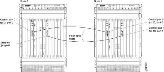
Figure 1 shows a pair of SRX5800 devices with dual control links connected. In this example, control port 0 and control port 1 are connected on different SPCs.

For SRX5600 devices and SRX5800 devices, you must connect control port 0 on one node to control port 0 on the other node. You must also connect control port 1 on one node to control port 1 on the other node. If you connect control port 0 to control port 1, the nodes cannot receive heartbeat packets across the control links.
See Also
Upgrade the Second Routing Engine When Using Chassis Cluster Dual Control Links on SRX5600 and SRX5800 Devices
You must use a second Routing Engine for each SRX5600 device and SRX5800 device in a cluster if you are using dual control links. The second Routing Engine does not provide backup functionality; its purpose is only to initialize the switch on the Switch Control Board (SCB). The second Routing Engine must be running Junos OS Release 12.1X47-D35, 12.3X48-D30, 15.1X49-D40, or later. For more information, see knowledge base article KB30371.
On SRX5600 devices and SRX5800 devices,
you
can use the show chassis hardware
command to see the serial number
and the hardware version details of the second Routing Engine. To use this
functionality, ensure that the second Routing Engine is running either Junos OS
Release 15.1X49-D70 or Junos OS Release 17.3R1.
Junos OS does not support dual control link functionality on the SRX5400 Services Gateways, due to limited slots.
Instead, use the primary Routing Engine to create a bootable USB storage device, which you can then use to install a software image on the second Routing Engine.
To upgrade the software image on the second Routing Engine:
Example: Configure Chassis Cluster Control Ports for Dual Control Links
This example shows how to configure chassis cluster control ports for use as dual control links on SRX5600 devices and SRX5800 devices. You need to configure the control ports that you will use on each device to set up the control links.
Junos OS does not support dual control links on SRX5400 devices, due to the limited number of slots.
Requirements
Before you begin:
Understand chassis cluster control links. See Understanding Chassis Cluster Control Plane and Control Links.
Physically connect the control ports on the devices. See Connecting SRX Series Devices to Create a Chassis Cluster.
Overview
By default, all control ports on SRX5600 devices and SRX5800 devices are disabled. After connecting the control ports, configuring the control ports, and establishing the chassis cluster, the control links are set up.
This example configures control ports with the following FPCs and ports as the dual control links:
FPC 4, port 0
FPC 10, port 0
FPC 6, port 1
FPC 12, port 1
Configuration
Procedure
CLI Quick Configuration
To quickly configure this section of the example,
copy the following commands, paste them into a text file, remove any
line breaks, change any details necessary to match your network configuration,
copy and paste the commands into the CLI at the [edit]
hierarchy
level, and then enter commit
from configuration mode.
{primary:node0}[edit] set chassis cluster control-ports fpc 4 port 0 set chassis cluster control-ports fpc 10 port 0 set chassis cluster control-ports fpc 6 port 1 set chassis cluster control-ports fpc 12 port 1
Step-by-Step Procedure
To configure control ports for use as dual control links for the chassis cluster:
Specify the control ports.
{primary:node0}[edit] user@host# set chassis cluster control-ports fpc 4 port 0 {primary:node0}[edit] user@host# set chassis cluster control-ports fpc 10 port 0 {primary:node0}[edit] user@host# set chassis cluster control-ports fpc 6 port 1 {primary:node0}[edit] user@host# set chassis cluster control-ports fpc 12 port 1
Results
In configuration mode, confirm your configuration by entering the show chassis
cluster
command. If the output does not display the intended
configuration, repeat the configuration instructions in this example to
correct it.
For brevity, this show
command output includes only
the configuration that is relevant to this example. Any other configuration
on the system has been replaced with ellipses (...).
{primary:node0}[edit] user@host# show chassis cluster ... control-ports { fpc 4 port 0; fpc 6 port 1; fpc 10 port 0; fpc 12 port 1; } ...
If you are finished configuring the device, enter commit
from configuration
mode.
Verification
Verification of the Chassis Cluster Status
Purpose
Verify the chassis cluster status.
Action
In operational mode, enter the show chassis cluster status
command.
{primary:node0} user@host> show chassis cluster status Cluster ID: 1 Node Priority Status Preempt Manual failover Redundancy group: 0 , Failover count: 1 node0 100 primary no no node1 1 secondary no no Redundancy group: 1 , Failover count: 1 node0 0 primary no no node1 0 secondary no no
Meaning
Use the show chassis cluster status command to confirm that the devices in the chassis cluster are communicating with each other. The output shows that the chassis cluster is functioning properly, as one device is the primary node and the other is the secondary node.
Resiliency with SCB Dual Control Links
On SRX5600 devices and SRX5800 devices, a Switch Control Board (SCB) card adds 10-Gigabit Ethernet (GbE) Small form-factor pluggables ports (SFPP) ports to provide redundancy. In a chassis cluster setup, you can configure these Ethernet ports as chassis cluster control ports to provide dual control links.
Dual control links help prevent a single point of failure by offering a redundant link for control traffic.
On SCB3 and SCB4, there are two external 10 Gbe ethernet ports located in the front panel. The left port (SCB Ethernet-switch port xe0) is used as the SCB HA port.
For SRX5600 devices and SRX5800 devices operating in chassis cluster, you can configure 10 Gigabit Ethernet ports on the SCB front panels to operate as chassis cluster control ports using Long Reach (LR), Short Reach (SR), and Long Reach Multimode (LRM) interfaces.
You can use the following 10GbE SFPP ports as chassis cluster control ports:
SCB | SFPP Ports |
---|---|
SCB2 |
SFPP-10GbE-LR SFPP-10GbE-SR SFPP-10GbE-LRM |
SCB3 and SCB4 |
SFPP-10GbE-LR SFPP-10GbE-SR |
For SRX Series Firewalls operating in chassis cluster, you can configure Ethernet ports on the SCB front panels to operate as chassis cluster control ports.
SRX5400 Services Gateways do not support dual control links, due to limited slots. These devices supports only chassis cluster control port 0.
Benefits of SCB Dual Control Links:
- Increase the resiliency of the chassis cluster.
- Maintain reliability of the chassis cluster in the event of an SPC failure.
Figure 2 shows a chassis cluster using SCB dual control links. The term HA used in the Figure 2 and Table 2 is referred to as chassis cluster.

The control port connections on the chassis cluster are as follows:
Primary Control Link | Secondary Control Link |
---|---|
SCB0 is Control Board 0. HA port 0 is on SCB0. | SCB1 is Control Board 1. HA port 1 is on SCB1. |
Routing Engine 0 is on SCB0. | Routing Engine 1 is on SCB1. |
The Ethernet port on SCB0 is used as HA port 0. | The Ethernet port on SCB1 is used as HA port 1. |
The control packets pass through the SCB control links instead of the SPC control links.
See Also
Example: Configure a Chassis Cluster Using SCB Dual Control Links
This example shows how to configure SCB dual control links on a chassis cluster.
In standalone mode, you must configure SCB dual control links and reboot the nodes to activate the changes.
Requirements
Before you begin:
-
Understand chassis cluster control links. See Understanding Chassis Cluster Control Plane and Control Links.
-
To support dual control links on SCB ports, upgrade both primary Routing Engine (RE0) and secondary Routing Engine (RE1) software to Junos OS 21.4R1 or later. For more information, see Upgrading the Second Routing Engine and ../../../../../../.
Overview
To configure dual control links in a chassis cluster, you connect primary and secondary control links between the SCB chassis cluster control ports as shown in Figure 2.
SCB control links have below properties:
- For RE0, SCB0 chassis cluster control port is automatically enabled when
system boots in chassis cluster mode.
SCB0 chassis cluster control port is automatically disabled when system boots in standalone mode.
- For RE1, SCB1 chassis cluster control port is automatically enabled after reboot, irrespective of whether the device is in chassis cluster mode or standalone mode.
- To temporary disable primary SCB contol link in chassis cluster mode,
disable the SCB0 control port on
RE0:
user@host> test chassis ethernet-switch shell-cmd "port xe0 enable=0"
To temporary disable secondary SCB control link, disable the SCB 1 control port on RE1:
user@host> test chassis ethernet-switch shell-cmd "port xe0 enable=0"
Note:These CLI commands will lose effect after redundancy group 0 failover or device reboot.
- To permanently disable primary SCB control link in chassis cluster mode:
- Option1: Delete the SCB control port configurations, add fake FPC control link configurations, and commit.
- Option2: Disconnect the primary SCB control link cable.
- To permanently disable secondary SCB control link in chassis cluster mode, disconnect the secondary SCB control link cable.
- To change from cluster mode to standalone mode when using dual SCB control links:Note:
Below steps are for temporary transition from cluster to standalone. If you need to change to standalone mode permanently, disconnect both the primary and secondary SCB control link cables.
- Disable SCB1 HA control ports on both nodes through
RE1:
user@host> test chassis ethernet-switch shell-cmd "port xe0 enable=0"
user@host> test chassis ethernet-switch shell-cmd ps | grep xe0
xe0 !ena 10G FD SW No Forward TX RX None FA XGMII 16356
- Reboot the RE0 to set as standalone
mode:
user@host> set chassis cluster disable reboot
- To enter the cluster mode again, enable the cluster mode on RE0 and
reboot and then enable SCB1 HA control ports on both nodes through
RE1
console:
user@host> test chassis ethernet-switch shell-cmd "port xe0 enable=1"
user@host> test chassis ethernet-switch shell-cmd ps | grep xe0
xe0 up 10G FD SW No Forward TX RX None FA XGMII 16356
- Check the chassis cluster status.
- Disable SCB1 HA control ports on both nodes through
RE1:
Configuration
Procedure
To configure SCB dual control links for the chassis cluster:
-
Connect the primary SCB control link cable.
-
Configure a chassis cluster that uses SCB0 control port for primary control link and SCB1 control port for secondary control link on both nodes.
[edit] user@host# set chassis cluster scb-control-ports 0 user@host# set chassis cluster scb-control-ports 1
-
Configure the chassis cluster. The example configuration is for node 0. For node 1, make sure to configure the same cluster ID.
[edit] user@host> set chassis cluster cluster-id 1 node 0
-
Reboot both nodes to activate cluster mode.
-
Connect the secondary SCB control link cable.
Verification
Verification of the Chassis Cluster Status
Purpose
Verify the chassis cluster status.
Action
In operational mode, enter the show chassis cluster
status
command.
{primary:node0} user@host> show chassis cluster status Monitor Failure codes: CS Cold Sync monitoring FL Fabric Connection monitoring GR GRES monitoring HW Hardware monitoring IF Interface monitoring IP IP monitoring LB Loopback monitoring MB Mbuf monitoring NH Nexthop monitoring NP NPC monitoring SP SPU monitoring SM Schedule monitoring CF Config Sync monitoring RE Relinquish monitoring IS IRQ storm Cluster ID: 1 Node Priority Status Preempt Manual Monitor-failures Redundancy group: 0 , Failover count: 1 node0 254 primary no no None node1 1 secondary no no None Redundancy group: 1 , Failover count: 1 node0 200 primary no no None node1 199 secondary no no None
In operational mode, enter the show chassis cluster
interfaces
command.
user@host> show chassis cluster interfaces Control link status: Up Control interfaces: Index Interface Monitored-Status Internal-SA Security 0 ixlv0 Up Disabled Disabled 1 igb0 Up Disabled Disabled Fabric link status: Up Fabric interfaces: Name Child-interface Status Security (Physical/Monitored) fab0 xe-3/0/7 Up / Up Disabled fab0 fab1 xe-15/0/7 Up / Up Disabled fab1 Redundant-ethernet Information: Name Status Redundancy-group reth0 Down Not configured reth1 Down Not configured Redundant-pseudo-interface Information: Name Status Redundancy-group lo0 Up 0
In operational mode, enter the show chassis cluster information
detail
command.
user@host> show chassis cluster information detail node0: -------------------------------------------------------------------------- Redundancy mode: Configured mode: active-active Operational mode: active-active Cluster configuration: Heartbeat interval: 2000 ms Heartbeat threshold: 8 Control link recovery: Disabled Fabric link down timeout: 352 sec Node health information: Local node health: Healthy Remote node health: Healthy Redundancy group: 0, Threshold: 255, Monitoring failures: none Events: May 6 17:38:01.665 : hold->secondary, reason: Hold timer expired Redundancy group: 1, Threshold: 255, Monitoring failures: none Events: May 6 17:38:01.666 : hold->secondary, reason: Hold timer expired Control link statistics: Control link 0: Heartbeat packets sent: 205193 Heartbeat packets received: 205171 Heartbeat packet errors: 0 Node 0 SCB HA port TX FCS Errors: 0 Node 0 SCB HA port RX FCS Errors: 0 Node 1 SCB HA port TX FCS Errors: 0 Node 1 SCB HA port RX FCS Errors: 0 Duplicate heartbeat packets received: 361 Control link 1: Heartbeat packets sent: 707 Heartbeat packets received: 697 Heartbeat packet errors: 0 Node 0 SCB HA port TX FCS Errors: NA Node 0 SCB HA port RX FCS Errors: NA Node 1 SCB HA port TX FCS Errors: NA Node 1 SCB HA port RX FCS Errors: NA Duplicate heartbeat packets received: 329
In operational mode, enter the show chassis cluster fpc
pic-status
command.
user@host> show chassis cluster fpc pic-status node0: -------------------------------------------------------------------------- Slot 2 Online SPC3 PIC 0 Online SPU Cp-Flow PIC 1 Online SPU Flow Slot 3 Online SRX5k IOC4 10G PIC 0 Online 20x10GE SFPP- np-cache/services-offload PIC 1 Online 20x10GE SFPP- np-cache/services-offload node1: -------------------------------------------------------------------------- Slot 2 Online SPC3 PIC 0 Online SPU Cp-Flow PIC 1 Online SPU Flow Slot 3 Online SRX5k IOC4 10G PIC 0 Online 20x10GE SFPP- np-cache/services-offload PIC 1 Online 20x10GE SFPP- np-cache/services-offload
Meaning
Use the show chassis cluster command to confirm that the devices in the chassis cluster are communicating with each other and functioning properly.
Transition from SPC Dual Control Links to SCB Dual Control Links
This example shows how to transition SPC dual control links to SCB dual control links. This procedure minimizes traffic disruption and prevents control plane loops during the control link transition.
Requirements
Before you begin:
-
Understand chassis cluster control links. See Understanding Chassis Cluster Control Plane and Control Links.
-
Learn how to physically connect both SPC control ports and SCB control ports. In this procedure, you must remove cables from and attach cables to both SPC and SCB cards. See Connecting SRX Series Devices to Create a Chassis Cluster.
Overview
In this example, you begin with a working chassis cluster that uses SPC dual control links. The goal is to transition the system to use SCB control links seamlessly. To prevent the formation of a control plane loop, the system must not actively forward over the two different control links at the same time.
Two combinations of simultaneous SPC and SCB control link connections ensure loop-free operation. As part of your transition strategy, you must decide on one of the following control link combinations:
- SPC as the primary control link with SCB as the secondary control link
- SCB as the primary control link with SPC as the secondary control link
The transition modes support both the combinations of simultaneous SPC and SCB control links to ensure that only one type of control links is forwarding. If both SPC and SCB control links are active at the same time, a loop can form.
Either supported option (SPC or SCB) works as well as the other. This example illustrates the first option. During the control link transition, the primary SPC control link remains active while you add a secondary SCB control link. Again, this state is transitory. After the transition, you have a chassis cluster with both the primary and secondary control links connected to the SCB port.
Control Links illustrates the process for transitioning from SPC control links to SCB control links.


The starting state of the chassis cluster before transition is displayed on the top. Two SPC control ports are used to form the cluster. In the middle, the transition state has one SPC control port and one SCB control port simultaneously connected. After transition, the ending state of the chassis cluster is displayed to the bottom. The chassis cluster operates with two SCB control links after removing the original SPC control links.
Transition Procedure: SPC to SCB with Dual Control Links
Procedure
To transition from SPC to SCB dual control links on the primary node (node 0):
-
Select the preferred transition approach. Refer to Transition Options. In this example, select the primary SPC link with a secondary SCB link as shown in Control Links.
-
Delete the SPC secondary control link configuration. This configuration change deletes both ends of the secondary SPC control links in the chassis cluster.
{primary:node0}[edit] user@host# delete chassis cluster control-ports fpc 2 port 1 user@host# delete chassis cluster control-ports fpc 14 port 1 user@host# commit
-
Disconnect the SPC secondary control link cable before proceeding.
-
Configure the SCB secondary control link and commit. The same SCB1 control port is used at both ends of the cluster. This single configuration statement applies to both node 0 and node 1.
{primary:node0}[edit] user@host# set chassis cluster scb-control-ports 1 user@host# commit
-
Connect the SCB secondary control link cable. At this time, the chassis cluster is in a transitional state.
- Before continuing the transition, you verify that the chassis cluster
is operational and that the dual control links are in a healthy state.
Use the
show chassis cluster interfaces
command.{primary:node0} user@host> show chassis cluster interfaces Control link status: Up Control interfaces: Index Interface Monitored-Status Internal-SA Security 0 ixlv0 Up Disabled Disabled 1 igb0 Up Disabled Disabled Fabric link status: Up Fabric interfaces: Name Child-interface Status Security (Physical/Monitored) fab0 xe-3/0/7 Up / Up Disabled fab0 fab1 xe-15/0/7 Up / Up Disabled fab1 Redundant-ethernet Information: Name Status Redundancy-group reth0 Down Not configured reth1 Down Not configured Redundant-pseudo-interface Information: Name Status Redundancy-group lo0 Up 0
In the preceding output, the
ixlv0
andigb0
interfaces are used to send cluster control traffic and keepalive traffic.{primary:node0} user@host> show chassis fpc pic-status node0: -------------------------------------------------------------------------- Slot 2 Online SPC3 PIC 0 Online SPU Cp-Flow PIC 1 Online SPU Flow Slot 3 Online SRX5k IOC4 10G PIC 0 Online 20x10GE SFPP- np-cache/services-offload PIC 1 Online 20x10GE SFPP- np-cache/services-offload node1: -------------------------------------------------------------------------- Slot 2 Online SPC3 PIC 0 Online SPU Cp-Flow PIC 1 Online SPU Flow Slot 3 Online SRX5k IOC4 10G PIC 0 Online 20x10GE SFPP- np-cache/services-offload PIC 1 Online 20x10GE SFPP- np-cache/services-offload
The chassis cluster control link reports
up
status. The remote node's cards (SPC and PIC) are reported asOnline
. The outputs confirm that the chassis cluster remains operational. -
Delete the SPC primary control link. The command deletes any remaining SPC control ports on both nodes.
user@host# delete chassis cluster control-ports user@host# commit
-
Disconnect the SPC primary control link cable before proceeding.
-
Configure the SCB primary control link.
user@host# set chassis cluster scb-control-ports 0 user@host# commit
-
Connect the SCB primary control link cable.
- Verify that the chassis cluster remains operational, using the
show chassis cluster interfaces
command.{primary:node0} user@host> show chassis cluster interfaces Control link status: Up Control interfaces: Index Interface Monitored-Status Internal-SA Security 0 ixlv0 Up Disabled Disabled 1 igb0 Up Disabled Disabled Fabric link status: Up Fabric interfaces: Name Child-interface Status Security (Physical/Monitored) fab0 xe-3/0/7 Up / Up Disabled fab0 fab1 xe-15/0/7 Up / Up Disabled fab1 Redundant-ethernet Information: Name Status Redundancy-group reth0 Down Not configured reth1 Down Not configured Redundant-pseudo-interface Information: Name Status Redundancy-group lo0 Up 0
{primary:node0} user@host> show chassis fpc pic-status node0: -------------------------------------------------------------------------- Slot 2 Online SPC3 PIC 0 Online SPU Cp-Flow PIC 1 Online SPU Flow Slot 3 Online SRX5k IOC4 10G PIC 0 Online 20x10GE SFPP- np-cache/services-offload PIC 1 Online 20x10GE SFPP- np-cache/services-offload node1: -------------------------------------------------------------------------- Slot 2 Online SPC3 PIC 0 Online SPU Cp-Flow PIC 1 Online SPU Flow Slot 3 Online SRX5k IOC4 10G PIC 0 Online 20x10GE SFPP- np-cache/services-offload PIC 1 Online 20x10GE SFPP- np-cache/services-offload
The chassis cluster control link reports an
up
status and the remote node's cards SPC and PIC are reported asOnline
.
Transition from SCB to SPC with Dual Control Links
This example provides steps for a control link transition from an SCB to an SPC dual control link concurrently.
Requirements
Before you begin:
-
Understand chassis cluster control links. See Understanding Chassis Cluster Control Plane and Control Links.
-
Physically connect the control ports on the devices. See Connecting SRX Series Devices to Create a Chassis Cluster.
Configuration
Procedure
To transition from SCB to SPC control links concurrently:
-
Delete the SCB secondary control link configuration.
{primary:node0}[edit] user@host# delete chassis cluster scb-control-ports 1 user@host# commit
-
Disconnect the SCB secondary control link cable.
-
Connect the SPC secondary control link cable.
-
Configure the SPC secondary control link, and commit.
{primary:node0}[edit] user@host# set chassis cluster control-ports fpc 2 port 1 user@host# set chassis cluster control-ports fpc 14 port 1 user@host# commit
-
Verify that both the primary and secondary control interfaces are up on both nodes.
In operational mode, enter the
show chassis cluster interfaces
command to confirm that the chassis cluster is functioning properly.{primary:node0} user@host> show chassis cluster interfaces Control link status: Up Control interfaces: Index Interface Monitored-Status Internal-SA Security 0 ixlv0 Up Disabled Disabled 1 igb0 Up Disabled Disabled Fabric link status: Up Fabric interfaces: Name Child-interface Status Security (Physical/Monitored) fab0 xe-3/0/7 Up / Up Disabled fab0 fab1 xe-15/0/7 Up / Up Disabled fab1 Redundant-ethernet Information: Name Status Redundancy-group reth0 Down Not configured reth1 Down Not configured Redundant-pseudo-interface Information: Name Status Redundancy-group lo0 Up 0
{primary:node0} user@host> show chassis fpc pic-status node0: -------------------------------------------------------------------------- Slot 2 Online SPC3 PIC 0 Online SPU Cp-Flow PIC 1 Online SPU Flow Slot 3 Online SRX5k IOC4 10G PIC 0 Online 20x10GE SFPP- np-cache/services-offload PIC 1 Online 20x10GE SFPP- np-cache/services-offload node1: -------------------------------------------------------------------------- Slot 2 Online SPC3 PIC 0 Online SPU Cp-Flow PIC 1 Online SPU Flow Slot 3 Online SRX5k IOC4 10G PIC 0 Online 20x10GE SFPP- np-cache/services-offload PIC 1 Online 20x10GE SFPP- np-cache/services-offload
-
Delete the SCB primary control link.
user@host# delete chassis cluster scb-control-ports 0 user@host# commit
-
Disconnect the SCB primary control link cable.
-
Connect the SPC primary control link cable.
-
Configure the SPC primary control link.
{primary:node0}[edit] user@host# set chassis cluster control-ports fpc 2 port 0 user@host# set chassis cluster control-ports fpc 14 port 0 user@host# commit
- Verify that both the primary and secondary control interfaces are up on
both nodes, using the
show chassis cluster interfaces
command.{primary:node0} user@host> show chassis cluster interfaces Control link status: Up Control interfaces: Index Interface Monitored-Status Internal-SA Security 0 ixlv0 Up Disabled Disabled 1 igb0 Up Disabled Disabled Fabric link status: Up Fabric interfaces: Name Child-interface Status Security (Physical/Monitored) fab0 xe-3/0/7 Up / Up Disabled fab0 fab1 xe-15/0/7 Up / Up Disabled fab1 Redundant-ethernet Information: Name Status Redundancy-group reth0 Down Not configured reth1 Down Not configured Redundant-pseudo-interface Information: Name Status Redundancy-group lo0 Up 0
{primary:node0} user@host> show chassis fpc pic-status node0: -------------------------------------------------------------------------- Slot 2 Online SPC3 PIC 0 Online SPU Cp-Flow PIC 1 Online SPU Flow Slot 3 Online SRX5k IOC4 10G PIC 0 Online 20x10GE SFPP- np-cache/services-offload PIC 1 Online 20x10GE SFPP- np-cache/services-offload node1: -------------------------------------------------------------------------- Slot 2 Online SPC3 PIC 0 Online SPU Cp-Flow PIC 1 Online SPU Flow Slot 3 Online SRX5k IOC4 10G PIC 0 Online 20x10GE SFPP- np-cache/services-offload PIC 1 Online 20x10GE SFPP- np-cache/services-offload