
NTP Time Synchronization on Chassis Cluster
This toipic explains how a Network Time Protocol (NTP) is used to synchronize time between the Routing Engine and the Packet Forwarding Engine on a standalone device, as well as between devices in a chassis cluster.
Use Feature Explorer to confirm platform and release support for specific features.
NTP Time Synchronization on Firewalls
In both standalone and chassis cluster modes, the primary Routing Engine runs the NTP process to obtain time from an external NTP server. Although the secondary Routing Engine also runs the NTP process, it cannot directly synchronize with the external NTP server due to network constraints. Instead, the secondary Routing Engine synchronizes its time with the primary Routing Engine using NTP.
NTP is used to:
-
Synchronize time from the primary Routing Engine to the secondary Routing Engine over the chassis cluster control link.
-
Obtain time from an external NTP server for the primary Routing Engine or a standalone Routing Engine.
-
Synchronize time from the Routing Engine's NTP process to the Packet Forwarding Engine.
Configure NTP time settings to define and enforce the NTP adjustment threshold, improving the security and flexibility of the NTP service.
See Also
Example: Simplify Network Management by Synchronizing the Primary and Backup Nodes with NTP
This example shows how to simplify management by synchronizing time between two Firewalls operating in a chassis cluster. Using a Network Time Protocol (NTP) server, the primary node's synchronizes time with the secondary node. NTP is also used to synchronize time between the Routing Engine and the Packet Forwarding Engine on a standalone device and between nodes in a chassis cluster. Synchronizing system clocks on both nodes of the chassis cluster is required to effectively manage the following items:
-
Real-time objects (RTO)
-
Licenses
-
Software updates
-
Node failovers
-
Analyzing system logs (syslogs)
Requirements
This example uses the following hardware and software components:
-
Firewalls operating in a chassis cluster
-
Junos OS Release 18.1R1 or later
Before you begin:
-
Understand the basics of the Network Time Protocol. See NTP Overview.
Overview
When Firewalls operate in chassis cluster mode, the secondary node cannot access an external NTP server through the revenue port. Junos OS supports synchronizing the secondary node's time with the primary node over the control link by configuring the NTP server on the primary node.
Topology
Figure 1 shows the time synchronization from the peer node using the control link.
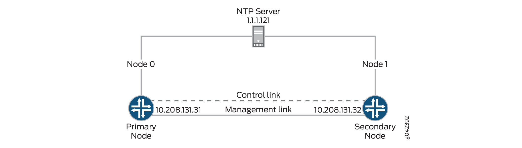
In the primary node, the NTP server is reachable. The NTP process on the primary node can synchronize the time from the NTP server, and the secondary node can synchronize the time with the primary node from the control link.
Configuration
CLI Quick Configuration
To quickly configure this example, and synchronize
the time from the NTP server, copy
the following commands, paste them into a text file, remove any line
breaks, change any details necessary to match your network configuration,
copy and paste the commands into the CLI at the [edit] hierarchy
level, and then enter commit from configuration mode.
set system ntp server 1.1.1.121
Synchronize Time from the NTP server
Step-by-Step Procedure
In this example, you configure the primary node to get its time from an NTP server at IP address 1.1.1.121. To synchronize the time from the NTP server:
-
Configure the NTP server.
{primary:node0}[edit] [edit system] user@host# set ntp server 1.1.1.121 -
Commit the configuration.
user@host#commit
Results
From configuration mode, confirm your configuration
by entering the show system ntp command. If the output
does not display the intended configuration, repeat the configuration
instructions in this example to correct it.
{primary:node0}[edit]
user@host# show system ntp
server 1.1.1.121
If you are done configuring the device, enter commit from configuration mode.
Verification
Confirm that the configuration is working properly.
Verify the NTP Configuration on the Primary Node
Purpose
Verify that the configuration is working properly.
Action
From operational mode, enter the show ntp associations command:
user@host> show ntp associations
 remote      refid      st t   when  poll  reach    delay    offset   jitter
==============================================================================
*1-1-1-121-dynami 10.208.0.50      4 -   63   64   65    4.909  -12.067   2.014
From operational mode, enter the show ntp status command:
user@host> show ntp status
status=0664 leap_none, sync_ntp, 6 events, event_peer/strat_chg,
version="ntpd 4.2.0-a Fri Mar 21 00:50:30 PDT 2014 (1)",
processor="i386", system="JUNOS12.1I20140320_srx_12q1_x47.1-637245",
leap=00, stratum=5, precision=-20, rootdelay=209.819,
rootdispersion=513.087, peer=14596, refid=1.1.1.121,
reftime=d6dbb2f9.b3f41ff7  Tue, Mar 25 2014 15:47:05.702, poll=6,
clock=d6dbb47a.72918b20  Tue, Mar 25 2014 15:53:30.447, state=4,
offset=-6.066, frequency=-55.135, jitter=4.343, stability=0.042
Meaning
The output on the primary and secondary node shows the NTP association as follows:
-
remote—Address or name of the remote NTP peer. -
refid—Reference identifier of the remote peer. If the reference identifier is not known, this field shows a value of 0.0.0.0. -
st—Stratum of the remote peer. -
t—Type of peer: b (broadcast), l (local), m (multicast), or u (unicast). -
when—When the last packet from the peer was received. -
poll—Polling interval, in seconds. -
reach—Reachability register, in octal. -
delay—Current estimated delay of the peer, in milliseconds. -
offset—Current estimated offset of the peer, in milliseconds. -
jitter—Magnitude of jitter, in milliseconds.
The output on the primary and secondary node shows the NTP status as follows:
-
status—System status word, a code representing the status items listed. -
x events—Number of events that have occurred since the last code change. An event is often the receipt of an NTP polling message. -
version—A detailed description of the version of NTP being used. -
processor—Current hardware platform and version of the processor. -
system—Detailed description of the name and version of the operating system in use. -
leap—Number of leap seconds in use. -
stratum—Stratum of the peer server. Anything greater than 1 is a secondary reference source, and the number roughly represents the number of hops away from the stratum 1 server. Stratum 1 is a primary reference, such as an atomic clock. -
precision—Precision of the peer clock, how precisely the frequency and time can be maintained with this particular timekeeping system. -
rootdelay—Total roundtrip delay to the primary reference source, in seconds. -
rootdispersion—Maximum error relative to the primary reference source, in seconds. -
peer—Identification number of the peer in use. -
refid—Reference identifier of the remote peer. If the reference identifier is not known, this field shows a value of 0.0.0.0. -
reftime—Local time, in timestamp format, when the local clock was last updated. If the local clock has never been synchronized, the value is zero. -
poll—NTP broadcast message polling interval, in seconds. -
clock—Current time on the local router clock. -
state—Current mode of NTP operation, where 1 is symmetric active, 2 is symmetric passive, 3 is client, 4 is server, and 5 is broadcast. -
offset—Current estimated offset of the peer, in milliseconds. Indicates the time difference between the reference clock and the local clock. -
frequency—Frequency of the clock. -
jitter—Magnitude of jitter, in milliseconds. -
stability—Measurement of how well this clock can maintain a constant frequency.
Verify NTP Configuration on the Secondary Node
Purpose
Verify that the configuration is working properly.
Action
From operational mode, enter the show ntp associations command:
user@host> show ntp associations
remote     refid    st  t     when  poll  reach  delay    offset   jitter
==============================================================================
 1-1-1-121-dynami .INIT.          16 -    - 1024    0    0.000    0.000  4000.00

*129.96.0.1      1.1.1.121         5 u   32   64  377    0.417    0.760   1.204
From operational mode, enter the show ntp status command:
user@host> show ntp status
status=0664 leap_none, sync_ntp, 6 events, event_peer/strat_chg,
version="ntpd 4.2.0-a Thu Mar 13 01:53:03 PDT 2014 (1)",
processor="i386", system="JUNOS12.1I20140312_srx_12q1_x47.2-635305",
leap=00, stratum=12, precision=-20, rootdelay=2.408,
rootdispersion=892.758, peer=51948, refid=1.1.1.121,
reftime=d6d646bb.853d2f42  Fri, Mar 21 2014 13:03:55.520, poll=6,
clock=d6d647bc.e8f28b2f  Fri, Mar 21 2014 13:08:12.909, state=4,
offset=-1.126, frequency=-62.564, jitter=0.617, stability=0.002