100GbE, 40GbE, and 10GbE
Read this topic for information about optics support that the specific line cards and devices provide.
Overview
Optical transmission leverages properties of light waves, including amplitude, phase, and polarization to optimize the capacity of a fiber optic link.
Optics supports Optical Transport Network (OTN), a standard defined by ITU G.709. The standard defines OTN as a set of optical network elements that are connected by optical fiber links.

Optics performs the following functions on optical channels that carry client signals:
-
Transport
-
Multiplexing
-
Switching
-
Management
-
Supervision
Optics bridges the gap between next-generation IP and legacy TDM networks. When you add optics to a Dense Wavelength Division Multiplexing (DWDM) network, you can easily manage a channel. For example, you can configure, troubleshoot, or see alarms. It is a standardized method for transparent transport of services over optical wavelengths. Hence, modification of the client signal does not occur when it passes through the DWDM network.
ITU G.709 standard ensures:
-
Performance monitoring and alarm management as specified in ITU standard.
-
Transparent transport of Ethernet signals with optical channel data unit 2 (ODU2) and ODU2e framing on a per-port basis.
-
Bit error rate (BER) based on pre-forward error correction (pre-FEC). Fast reroute (FRR) uses the pre-FEC BER as an indication of the an OTN link condition.
Benefits
The OTN provides the following benefits:
-
Enables FEC and thus improves system performance.
-
Enables alarm handling and thus improves system monitoring.
-
Protects the network from mixing of heterogeneous services, saves bandwidth, and transfers any traffic transparently.
-
Supports dedicated Ethernet links at 1GbE, 10GbE, 40GbE, and 100GbE and thus improves scalability.
Supported Features
|
Features |
Description |
|---|---|
|
Interface |
Supports:
|
|
Attributes:
|
|
|
Performance monitoring (15-minute and 1-day performance monitoring and historic statistics):
|
|
|
L2 and L3 Features |
Supports:
|
|
Threshold Crossing Alarms |
You receive TCA when you cross a certain configurable threshold (near-end measurement threshold or far-end measurement threshold). The TCA remains until the end of the 15-minute interval for parameters such as OTU and ODU |
|
Supported alarms:
|
OTN Alarms and Defects
|
OTN Alarms and Defects |
Description |
|---|---|
|
CSF |
Client Signal Failure |
|
LOS |
Loss of signal |
|
LOF |
Loss of frame |
|
LOM |
Loss of multi frame |
|
SSF |
Server Signal Failure |
|
TSF |
Trail Signal Fail |
|
OTU-FEC-DEG |
FEC Degraded |
|
OTU-FEC-EXE |
Excessive Errors, FEC_FAIL from the transponder |
|
OTU-AIS |
Alarm Indication Signal |
|
OTU-BDI |
Backward Defect Identification |
|
OTU-IAE |
Incoming Alignment Error |
|
OTU-TTIM |
Destination Access Point Identifier [DAPI], Source Access Point Identifier [SAPI], or both mismatch from expected to be received. |
|
OTU-SD |
Signal Degrade |
|
OTU-SF |
Signal Fail |
|
ODU-LCK |
ODU lock triggers for PM [path monitoring] |
|
ODU-AIS |
Alarm indication signal |
|
ODU-OCI |
Open connection indication |
|
ODU-BDI |
Backward defect indication |
|
ODU-IAE |
Incoming alignment error |
|
ODU-DAPI-TTIM |
DAPI or DAPI/SAPI mismatch from expected to receive. |
|
ODU-SAPI-TTIM |
SAPI or DAPI/SAPI mismatch from expected to receive. |
|
ODU-BEI |
Backward Error Indication |
|
ODU-SSF |
Server Signal Fail |
|
ODU-TSF |
Trail Signal Fail |
|
ODU-SD |
Signal Degrade. |
|
ODU-SF |
Signal Fail |
|
OPU-PTM |
Payload Type Mismatch. |
Supported PICs
Table 1 describes PICs that support optics.
| PIC | |
|---|---|
|
PTX3000: Junos OS Release 13.2R2 and later PTX5000: Junos OS Release 12.3R2 and later Junos OS Release 13.2R1 and later |
|
|
Junos OS Release 15.1F6 Junos OS Release 16.1R2 and later Junos OS Release 17.1R1 and later |
|
|
Junos OS Release 15.1F5 and 15.1F6 Junos OS Release 17.1R1 and later |
|
|
PTX3000: Junos OS Release 15.1F6, Junos OS Release 17.1R1 and later PTX5000: Junos OS Release 15.1F6, Junos OS Release 17.1R1 and later |
Configure Optics
This topic provides information about how to configure optics interface, OTN options on an interface, and optics options on an interface.
Configure Interfaces.
To configure the interface-specific options:
Configure OTN Options on the interface
To configure the OTN-related options on the interface:
-
Go to the
[edit interface interface-name
                                otn-options]
hierarchy level:[edit interfaces interface-name] user@host# edit otn-options
-
Enable the OTN mode as OTU2e, OTU1e, or OTU2 for the interface.
[edit interfaces interface-name otn-options]
user@host# set rate fixed-stuff-bytes|no-fixed-stuff-bytes|oc192
Note:fixed-stuff-bytesis for OTU2e rate,no-fixed-stuff-bytesis for OTU1e rate andoc192is for OTU2 rate. OTU2e and OTU1e rates are applicable for LAN PHY framing mode. OTU2 is applicable for WAN PHY framing mode. Framing mode is to set through theset interfaces framingconfiguration statement. -
Enable the laser on the OTN interface. The laser is disabled by default for all OTN interfaces.
[edit interfaces interface-name otn-options]
user@host# set laser-enable
-
Set a trail trace identifier for the source access point and for the destination access point for ODU and OTU on the OTN interface.
[edit interfaces interface-name otn-options]
user@host# set tti (odu-dapi | odu-expected-receive-dapi | odu-expected-receive-sapi | odu-sapi | otu-dapi | otu-expected-receive-dapi | otu-expected-receive-sapi | otu-sapi) tti-identifier
-
Ignore the trigger for the defect or set the hold time.
Configure the hold time for the defect trigger as:
-
up with a value—Wait for the hold time delay before clearing the alarm when the defect is absent on the OTN interface.
-
down with a value—Wait for the hold time delay before raising the alarm when the defect occurs for the OTN interface.
[edit interfaces interface-name otn-options]
user@host# set trigger (oc-lof | oc-lom | oc-los | oc-tsf | odu-ais | odu-bdi | odu-bei | odu-iae | odu-lck | odu-oci | odu-sd | odu-ttim |opu-ptim | otu-ais | otu-bdi | otu-fec-deg | otu-fec-exe | otu-iae | otu-sd | otu-ttim) (hold-time (down value | up value) | ignore)
-
-
Enable the threshold crossing alarms for the OTN interface along with the trigger for the defect.
[edit interfaces interface-name otn-options]
user@host# set tca (odu-tca-bbe | odu-tca-es | odu-tca-ses | odu-tca-uas | otu-tca-bbe | otu-tca-es |  otu-tca-ses | otu-tca-uas ) (enable-tca | no-enable-tca | threshold)
-
Set the OTN header bytes as a transmit payload type from 0 bytes through 255 bytes for the packets that are transmitted on the OTN interface.
[edit interfaces interface-name otn-options]
user@host# set bytes transmit-payload-type value
-
Configure the forward error correction (FEC) mode as Generic Forward Error Correction (GFEC), Enhanced Forward Error Correction (EFEC), Ultra Forward Error Correction (UFEC), or no-FEC (none) for the OTN interface.
[edit interfaces interface-name otn-options]
user@host# set fec (gfec | ufec | efec | none)
-
Enable a consequent action as listed in the ITU-T G.798 standard for ODU trail trace identifier mismatch (TTIM) on the OTN interface.
[edit interfaces interface-name otn-options]
user@host# set odu-ttim-action-enable
-
Enable a consequent action as listed in the ITU-T G.798 standard for OTU trail trace identifier mismatch (TTIM) on the OTN interface.
[edit interfaces interface-name otn-options]
user@host# set otu-ttim-action-enable
-
Configure the threshold value for signal degradation when an alarm needs to be raised. Configure the threshold value after signal degradation when the alarm needs to be cleared. When you configure the interval along with the
ber-threshold-signal-degrade
                                    value
statement, the bit error rate (BER) must remain above the signal degradation threshold for the configured interval after which the alarm is raised. When the interval is configured along with theber-threshold-clear valuestatement, then BER must remain below the clear threshold for the configured interval after which the alarm is cleared.[edit interfaces interface-name otn-options signal-degrade] user@host# set ber-threshold-signal-degrade value user@host# set ber-threshold-clear value user@host# set interval value
-
Enable the following actions for the
preemptive-fast-reroutestatement:-
Backward FRR—Insert the local pre-FEC status into the transmitted OTN frames and monitor the received OTN frames for the pre-FEC status.
[edit interfaces interface-name otn-options preemptive-fast-reroute]
user@host# set backward-frr-enable
-
Monitoring of signal degradation of pre-FEC OTN frames.
[edit interfaces interface-name otn-options preemptive-fast-reroute]
user@host# set signal-degrade-monitor-enable
-
Configure Optics Options on the interface
To configure the optics-specific options on the interface:
-
Specify the modulation format at the [
edit interface
                                    interface-name optics-options
] hierarchy level.[edit interfaces interface-name optics-options] user@host# set modulation-format (qpsk|8qam|16qam)
-
Specify encoding.
[edit interfaces interface-name optics-options]
user@host# set encoding (differential|non-differential)
-
Specify the optical transmit laser output power in dBm at the [
edit interface interface-name
                                optics-options
] hierarchy level. The default transmit laser output value is 0 dBm.[edit interfaces interface-name optics-options] user@host# set tx-power value
-
Specify the wavelength of the optics in nanometers.
[edit interfaces interface-name optics-options]
user@host# set wavelength nm
See Also
Supported OTN and Optics Options
Read this topic for information about the supported optics options and OTN options on specific devices.
- Supported OTN Options on ACX6360 and ACX5448 Routers
- Supported OTN Options on MX Series Routers
- Supported OTN Options on PTX Series Routers
- Supported Optics Options on ACX6360 and ACX5448-D Routers
- Supported Optics Options on PTX10008 and PTX10016 Series Routers
Supported OTN Options on ACX6360 and ACX5448 Routers
Table 4 lists the
statements that are supported on Juniper Networks® ACX6360 and ACX5448 routers at the
[edit interfaces interface-name
    otn-options]
hierarchy
level. Note that the term NA denotes that the statement is not applicable for that
particular component:
|
Statement |
Options |
ACX6360 (18.3R1) |
ACX5448 (19.2R1) |
|---|---|---|---|
|
|
|
Yes |
Yes |
|
|
- |
Yes |
Yes |
|
|
- |
Yes |
Yes |
|
|
- |
Yes |
Yes |
|
|
- |
Yes |
Yes |
|
|
- |
Yes |
Yes |
|
|
- |
Yes |
Yes |
|
|
- |
Yes |
Yes |
|
|
- |
Yes |
Yes |
|
|
|
Yes |
Yes |
|
|
Yes |
Yes |
|
|
|
No |
No |
|
|
|
No |
No |
|
|
|
|
Yes |
Yes |
|
|
Yes |
Yes |
|
|
|
Yes |
Yes |
|
|
|
Yes |
Yes |
|
|
|
Yes |
Yes |
|
|
|
Yes |
Yes |
|
|
|
Yes |
Yes |
|
|
|
Yes |
Yes |
|
|
|
Yes |
Yes |
|
|
|
Yes |
Yes |
|
|
|
Yes |
Yes |
|
|
|
Yes |
Yes |
|
|
|
Yes |
Yes |
|
|
|
Yes |
Yes |
|
|
|
Yes |
Yes |
|
|
|
|
Yes |
Yes |
|
|
Yes |
Yes |
|
|
|
Yes |
Yes |
|
|
|
Yes |
Yes |
|
|
|
Yes |
Yes |
|
|
|
Yes |
Yes |
|
|
|
Yes |
Yes |
|
|
|
Yes |
Yes |
|
|
|
Yes |
Yes |
|
|
|
Yes |
Yes |
|
|
|
Yes |
Yes |
|
|
|
Yes |
Yes |
|
|
|
Yes |
Yes |
|
|
|
Yes |
Yes |
|
|
|
Yes |
Yes |
|
|
|
Yes |
Yes |
|
|
|
Yes |
Yes |
|
|
|
|
Yes |
Yes |
|
|
Yes |
Yes |
|
|
|
Yes |
Yes |
|
|
|
Yes |
Yes |
|
|
|
Yes |
Yes |
|
|
|
Yes |
Yes |
|
|
|
Yes |
Yes |
|
|
|
Yes |
Yes |
See Also
Supported OTN Options on MX Series Routers
Table 5 lists the statements that
are supported on 100-Gigabit Ethernet MICs on Juniper Networks® MX Series
Universal Routers at the [edit interfaces
interface-Nome otn-options]
hierarchy level.
Statement |
Options |
MIC6-100G-CFP2(MX2010 / MX2020) (13.3R3) |
MIC3-100G-DWDM (MX240, MX480, MX960, MX2010, and MX2020) (15.1F5) |
|
|---|---|---|---|---|
|
|
No |
Yes |
|
|
|
Yes ( |
Yes ( |
|
|
- |
Yes |
Yes |
|
|
- |
Yes |
Yes |
|
|
- |
Yes |
Yes |
|
|
- |
Yes |
Yes |
|
|
- |
Yes |
Yes |
|
|
- |
Yes |
Yes |
|
|
|
No |
Yes |
|
|
No |
Yes |
||
|
No |
Yes |
||
|
No |
Yes |
||
|
|
Yes |
Yes |
|
|
Yes |
Yes |
||
|
Yes |
Yes |
||
|
- |
Yes |
Yes |
|
|
- |
Yes |
Yes |
|
|
- |
Yes |
Yes |
|
|
|
Yes |
Yes |
|
|
Yes |
Yes |
||
|
No |
Yes |
||
|
No |
Yes |
||
|
|
Yes |
Yes |
|
|
Yes |
Yes |
||
|
Yes |
Yes |
||
|
Yes ( |
Yes ( |
||
|
|
Yes |
Yes |
|
|
Yes |
Yes |
||
|
Yes |
Yes |
||
|
No |
Yes |
||
|
No |
Yes |
||
|
|
Yes |
Yes |
|
|
Yes |
Yes |
||
|
Yes |
Yes |
||
|
Yes |
Yes |
||
|
Yes |
Yes |
||
|
Yes |
Yes |
||
|
Yes |
Yes |
||
|
Yes |
Yes |
||
|
Yes |
Yes |
||
|
Yes |
Yes |
||
|
Yes |
Yes |
||
|
Yes |
Yes |
||
|
Yes |
Yes |
||
|
Yes |
Yes |
||
|
Yes |
Yes |
||
|
Yes |
Yes |
||
transport-monitoring |
- |
No |
Yes |
|
|
|
Yes |
Yes |
|
|
Yes |
Yes |
||
|
Yes |
Yes |
||
|
No |
Yes |
||
|
No |
Yes |
||
|
Yes |
Yes |
||
|
Yes |
Yes |
||
|
Yes |
Yes |
||
|
Yes |
Yes |
||
|
Yes |
Yes |
||
|
Yes |
Yes |
||
|
Yes |
Yes |
||
|
Yes |
No |
||
|
Yes |
No |
||
|
Yes |
No |
||
|
Yes |
Yes |
||
|
Yes |
Yes |
||
|
Yes |
Yes |
||
|
Yes |
Yes |
||
|
No |
Yes |
||
|
No |
Yes |
||
|
Yes |
Yes |
||
|
Yes |
Yes |
||
|
Yes |
No |
||
|
Yes |
No |
||
|
Yes |
No |
||
|
Yes |
Yes |
||
|
|
Yes |
Yes |
|
|
No |
Yes |
||
|
Yes |
Yes |
||
|
No |
Yes |
||
|
Yes |
Yes |
||
|
Yes |
Yes |
||
|
No |
Yes |
||
|
Yes |
Yes |
||
|
No |
Yes |
||
|
Yes |
Yes |
||
|
No |
Yes |
||
|
Yes |
Yes |
||
|
No |
Yes |
||
|
Yes |
Yes |
||
|
No |
Yes |
||
See Also
Supported OTN Options on PTX Series Routers
Table 6 lists the statements that are supported on 100-Gigabit Ethernet PICs on Juniper Networks® PTX
Series Routers at the [edit interfaces interface-name
otn-options] hierarchy level.
|
Statement |
Options |
P1-PTX-2-100G-WDM (PTX5000 / PTX3000) (13.2R1 / 13.3R1) |
P2-100GE-OTN (PTX5000) (14,1R2 / 14.2R1) |
P1-PTX-24-10G-W-SFPP (PTX5000) (14.2R1) |
PTX10K-LC1104 (PTX10008 and PTX10016) (18.3R1) |
|
|---|---|---|---|---|---|---|
|
|
|
Yes |
Yes |
Yes |
Yes |
|
|
|
|
Yes |
Yes ( |
Yes |
Yes |
|
|
|
- |
Yes |
Yes |
Yes |
Yes |
|
|
|
- |
Yes |
Yes |
Yes |
Yes |
|
|
|
- |
Yes |
NA |
Yes |
Yes |
|
|
|
- |
Yes |
Yes |
Yes |
Yes |
|
|
|
- |
Yes |
Yes |
Yes |
Yes |
|
|
|
- |
Yes |
Yes |
Yes |
Yes |
|
|
|
|
Yes |
No |
No |
Yes |
|
|
|
Yes |
No |
No |
Yes |
||
|
|
Yes |
No |
No |
Yes |
||
|
|
Yes |
No |
No |
Yes |
||
|
|
|
No No |
Yes |
No |
Yes |
|
|
|
No No |
Yes |
No |
Yes |
||
|
|
No |
Yes |
No |
Yes |
||
|
|
- |
Yes |
Yes |
Yes |
Yes |
|
|
|
- |
Yes |
Yes |
Yes |
Yes |
|
|
|
- |
Yes |
Yes |
Yes |
Yes |
|
|
|
|
Yes |
Yes |
Yes |
Yes |
|
|
|
Yes |
Yes |
Yes |
Yes |
||
|
|
No |
Yes |
No |
Yes |
||
|
|
No |
Yes |
No |
Yes |
||
|
|
|
Yes |
No |
Yes |
Yes |
|
|
|
Yes |
No |
Yes |
Yes |
||
|
|
Yes |
Yes |
No |
Yes |
||
|
|
Yes |
No |
No |
Yes |
||
|
|
|
Yes |
Yes |
Yes |
Yes |
|
|
|
Yes |
Yes |
Yes |
Yes |
||
|
|
Yes |
Yes |
Yes |
Yes |
||
|
|
|
Yes |
Yes |
Yes |
Yes |
|
|
|
Yes |
No |
Yes |
Yes |
||
|
|
Yes |
Yes |
Yes |
Yes |
||
|
|
Yes |
No |
Yes |
Yes |
||
|
|
Yes |
Yes |
Yes |
Yes |
||
|
|
Yes |
No |
Yes |
Yes |
||
|
|
Yes |
Yes |
Yes |
Yes |
||
|
|
Yes |
Yes |
Yes |
Yes |
||
|
|
Yes |
No |
Yes |
Yes |
||
|
|
Yes |
Yes |
Yes |
Yes |
||
|
|
Yes |
No |
Yes |
Yes |
||
|
|
Yes |
Yes |
Yes |
Yes |
||
|
|
Yes |
Yes |
Yes |
Yes |
||
|
|
Yes |
No |
Yes |
Yes |
||
|
|
Yes |
Yes |
Yes |
Yes |
||
|
|
Yes |
No |
Yes |
Yes |
||
|
transport-monitoring |
- |
No |
No |
Yes |
Yes |
|
|
|
|
Yes |
Yes |
Yes |
Yes |
|
|
|
Yes |
Yes |
Yes |
Yes |
||
|
|
Yes |
Yes |
Yes |
Yes |
||
|
|
Yes |
Yes |
Yes |
Yes |
||
|
|
Yes |
No |
Yes |
Yes |
||
|
|
Yes |
Yes |
Yes |
Yes |
||
|
|
Yes |
Yes |
Yes |
Yes |
||
|
|
Yes |
Yes |
Yes |
Yes |
||
|
|
Yes |
Yes |
Yes |
Yes |
||
|
|
Yes |
Yes |
Yes |
Yes |
||
|
|
Yes |
Yes |
Yes |
Yes |
||
|
|
Yes |
Yes |
Yes |
Yes |
||
|
|
Yes |
Yes |
Yes |
Yes |
||
|
|
Yes |
Yes |
Yes |
Yes |
||
|
|
Yes |
Yes |
Yes |
Yes |
||
|
|
Yes |
Yes |
Yes |
Yes |
||
|
|
Yes |
Yes |
Yes |
Yes |
||
|
|
Yes |
Yes |
Yes |
Yes |
||
|
|
Yes |
Yes |
Yes |
Yes |
||
|
|
Yes |
Yes |
Yes |
Yes |
||
|
|
Yes |
Yes |
Yes |
Yes |
||
|
|
|
Yes |
14.1R2 14.2 |
Yes |
Yes |
|
|
|
Yes |
Yes |
Yes |
Yes |
||
|
|
Yes |
Yes |
Yes |
Yes |
||
|
|
Yes |
Yes |
Yes |
Yes |
||
|
|
Yes |
Yes |
Yes |
Yes |
||
|
|
Yes |
Yes |
Yes |
Yes |
||
|
|
Yes |
Yes |
Yes |
Yes |
||
|
|
Yes |
Yes |
Yes |
Yes |
||
Supported Optics Options on ACX6360 and ACX5448-D Routers
Table 7 lists the statements that
are supported on ACX6360 and ACX5448-D routers at the [edit interfaces interface-name optics-options] hierarchy level.
Statement |
Options |
Release (18.2R1, 18.3R1, and 19.2R1-S1) |
Interfaces Supported |
|
|---|---|---|---|---|
fec |
|
Yes |
ot |
|
high-polarization |
- |
Yes |
ot |
|
|
- |
Yes |
ot |
|
|
- |
Yes |
ot |
|
|
- |
Yes |
ot |
|
modulation-format |
|
Yes |
ot |
|
|
|
Yes |
ot |
|
|
Yes |
|||
|
Yes |
|||
|
Yes |
|||
|
Yes |
|||
|
|
Yes |
ot |
|
|
Yes |
|||
|
Yes |
|||
|
Yes |
|||
|
Yes |
|||
|
Yes |
|||
|
Yes |
|||
|
Yes |
|||
|
Yes |
|||
|
Yes |
|||
|
Yes |
|||
|
Yes |
|||
|
Yes |
|||
|
Yes |
|||
|
Yes |
|||
|
Yes |
|||
|
Yes |
|||
|
Yes |
|||
|
Yes |
|||
tx-power |
dbm |
Yes |
ot |
|
wavelength |
nm |
Yes |
ot |
|
See Also
Supported Optics Options on PTX10008 and PTX10016 Series Routers
Table 8 lists the statements that are supported on Juniper Networks® PTX10008 Router and Juniper
Networks® PTX10016 Series Router at the [edit interfaces
interface-name optics-options] hierarchy level.
Statement |
Options |
Release (18.3R1) |
Interfaces Supported |
|
|---|---|---|---|---|
alarm low-light-alarm |
link-down | syslog |
Yes |
ot |
|
tca carrier-frequency-offset-high-tca |
|
Yes |
ot |
|
tx-power |
dbm |
Yes |
ot |
|
warning low-light-warning |
link-down | syslog |
Yes |
ot |
|
|
- |
Yes |
ot |
|
|
- |
Yes |
ot |
|
|
- |
Yes |
ot |
|
|
|
Yes |
ot |
|
|
Yes |
|||
|
Yes |
|||
|
|
Yes |
ot |
|
|
Yes |
|||
|
Yes |
|||
|
Yes |
|||
|
Yes |
|||
|
Yes |
|||
|
Yes |
|||
|
Yes |
|||
|
Yes |
|||
|
Yes |
|||
|
Yes |
|||
|
Yes |
|||
|
Yes |
|||
|
Yes |
|||
|
Yes |
|||
|
|
Yes |
ot |
|
|
Yes |
|||
|
Yes |
|||
|
Yes |
|||
|
Yes |
|||
|
Yes |
|||
|
Yes |
|||
|
Yes |
|||
|
Yes |
|||
|
Yes |
|||
|
Yes |
|||
|
Yes |
|||
|
Yes |
|||
|
Yes |
|||
|
Yes |
|||
|
Yes |
|||
|
Yes |
|||
|
Yes |
|||
|
Yes |
|||
|
Yes |
|||
|
Yes |
|||
Forward Error Correction and Bit Error Rate
OTN interfaces use pre-forward error correction (pre-FEC) BER for monitoring the condition of an OTN link. Read this topic to understand more about how OTN links and the supported FEC modes on devices.
- Overview
- Supported Forward Error Correction Modes
- ODU Path Delay Measurement for Performance Monitoring
Overview
Optical interfaces on PTX Series support monitoring the condition of an optical link by using the pre-forward error correction (pre-FEC) bit error rate (BER). The following PICs support pre-FEC BER monitoring:
P1-PTX-2-100G-WDM
P2-100GE-OTN
P1-PTX-24-10G-W-SFPP
The PICs use forward error correction (FEC) to correct bit errors in the received data. As long as the pre-FEC BER is below the FEC limit, all bit errors are successfully identified and corrected and, therefore, no packet loss occurs. The system monitors the pre-FEC BER on each port. This gives an early warning of link degradation. By configuring an appropriate pre-FEC BER threshold and interval, you enable the PIC to take preemptive action before the FEC limit is reached. If you combine the pre-FEC BER threshold logic with MPLS fast reroute, then you can prevent or minimize packet loss.
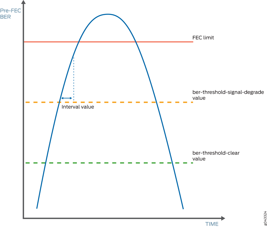
You must specify both the signal degradation threshold (ber-threshold-signal-degrade) and the interval (interval) for the interface. The threshold defines the BER criteria for a signal degrade condition and the interval defines the minimum duration over which the BER must exceed the threshold before an alarm is raised. The relationship between the threshold and the interval is illustrated in Figure 1. After an alarm is raised, if the BER returns to a level below the threshold clear value (ber-threshold-clear), the alarm is cleared.
With pre-FEC BER monitoring enabled, when the configured pre-FEC BER signal degrade threshold is reached, the PIC stops forwarding packets to the remote interface and raises an interface alarm. Ingress packets continue to be processed. If pre-FEC BER monitoring is used with MPLS fast reroute or another link protection method, then traffic is rerouted to a different interface.
You can also configure backward fast reroute to insert the local pre-FEC status into transmitted optical frames, notifying the remote interface of signal degradation. The remote interface can use the information to reroute traffic to a different interface. If you use pre-FEC BER monitoring together with backward fast reroute, then notification of signal degradation and rerouting of traffic occurs in less time than that required through a Layer 3 protocol.
Include the signal-degrade-monitor-enable and backward-frr-enable statements at the [edit interfaces interface-name otn-options preemptive-fast-reroute] hierarchy
level to enable pre-FEC BER monitoring and backward fast reroute.
When you configure pre-FEC BER signal degrade monitoring,
we recommend that you configure both the signal-degrade-monitor-enable and the backward-frr-enable statements.
You can also configure the pre-FEC BER thresholds that raise or clear a signal degrade alarm and the time interval for the thresholds. If the BER thresholds and interval are not configured, the default values are used.
When a received signal degrade alarm is active and backward fast reroute is enabled, a specific flag is inserted into the trasmitted optics overhead. The remote PIC at the opposite end of the link monitors the optics overhead, thus enabling both ends to initiate traffic rerouting in the event of a signal degrade condition. When the signal degrade condition is cleared, the overhead flag is returned to a normal state.
The pre-FEC BER signal degrade threshold value defines a specific amount of system margin relative to the BER correction limit (or FEC limit) of the PIC’s receive FEC decoder. Each PIC has a set FEC limit—it is intrinsic to the FEC decoder implementation.
The examples below use Q2-factor measurements (also known as Q-factor). Q2-factor is expressed in units of decibels relative to a Q2-factor of zero (dBQ). Q2-factor enables you to describe system margin in linear terms in contrast to BER values, which are nonlinear in nature. After you determine the thresholds, you must convert the threshold values from Q2-factor to BER to enter them in the CLI by using scientific notation. BER can be converted to Q2-factor by using the following equation:
Q2-factor = 20 * log10 (sqrt(2) * erfcinv(2 * BER))
To convert between Q2-factor and BER in a spreadsheet program, you can approximate the values by using the following formulas:
To calculate Q2-factor:
= 20 * LOG10(–NORMSINV(BER))
To calculate BER:
= 1 – NORMSDIST(10^(0.05 * Q2-factor))
Include the ber-threshold-signal-degrade, ber-threshold-clear, and interval statements at the [edit interfaces interface-name otn-options signal-degrade] hierarchy
level to configure the BER thresholds and time interval.
Configuring a high BER threshold for signal degradation and a long interval might cause the internal counter register to be saturated. Such a configuration is ignored by the router, and the default values are used instead. A system log message is logged for this error.
Signal Degrade and Clear Threshold Values for PICs
Table 9 shows the relationship between the fixed FEC limit, the configurable signal degrade threshold, and the configurable clear threshold for different PICs. In this example, approximately 1 dBQ of system margin has been set between the FEC limit, signal degrade threshold, and clear threshold.
|
PIC |
FEC Type |
FEC Limit |
Signal Degrade Threshold |
Clear Threshold |
|||
|---|---|---|---|---|---|---|---|
| Q2-Factor | BER | Q2-Factor | BER | Q2-Factor | BER | ||
|
P1-PTX-2-100G-WDM |
SD-FEC |
6.7 dBQ |
1.5E–2 |
7.7 dBQ |
7.5E–3 |
8.7 dBQ |
3.0E–3 |
|
P2-100GE-OTN |
G.709 GFEC |
11.5 dBQ |
8.0E–5 |
12.5 dBQ |
1.1E–5 |
13.5 dBQ |
1.0E–6 |
|
P1-PTX-24-10G-W-SFPP |
G.975.1 I.4 (UFEC) |
9.1 dBQ |
2.2E–3 |
10.1 dBQ |
6.9E–4 |
11.1 dBQ |
1.6E–4 |
|
G.975.1 I.7 (EFEC) |
9.6 dBQ |
1.3E–3 |
10.6 dBQ |
3.6E–4 |
11.6 dBQ |
7.5E–5 |
|
|
G.709 GFEC |
11.5 dBQ |
8.0E–5 |
12.5 dBQ |
1.1E–5 |
13.5 dBQ |
1.0E–6 |
|
To adjust the signal degrade threshold, you must first decide on a new system margin target and then calculate the respective BER value (using the equation to convert from Q2-factor to BER). Table 10 shows the values if 3 dBQ of system margin relative to the FEC limit is required for the signal degrade threshold (while maintaining the clear threshold at 1 dBQ relative to the signal degrade threshold).
The choice of system margin is subjective, as you might want to optimize your thresholds based on different link characteristics and fault tolerance and stability objectives. For guidance about configuring pre-FEC BER monitoring and BER thresholds, contact your Juniper Networks representative.
|
PIC |
FEC Type |
FEC Limit |
Signal Degrade Threshold |
Clear Threshold |
|||
|---|---|---|---|---|---|---|---|
| Q2-Factor | BER | Q2-Factor | BER | Q2-Factor | BER | ||
|
P1-PTX-2-100G-WDM |
SD-FEC |
6.7 dBQ |
1.5E–2 |
9.7 dBQ |
1.1E–3 |
10.7 dBQ |
2.9E–4 |
|
P2-100GE-OTN |
G.709 GFEC |
11.5 dBQ |
8.0E–5 |
14.5 dBQ |
4.9E–8 |
15.5 dBQ |
1.1E–9 |
|
P1-PTX-24-10G-W-SFPP |
G.975.1 I.4 (UFEC) |
9.1 dBQ |
2.2E–3 |
12.1 dBQ |
2.8E–5 |
13.1 dBQ |
3.1E–6 |
|
G.975.1 I.7 (EFEC) |
9.6 dBQ |
1.3E–3 |
12.6 dBQ |
1.1E–5 |
13.6 dBQ |
9.1E–7 |
|
|
G.709 GFEC |
11.5 dBQ |
8.0E–5 |
14.5 dBQ |
4.8E–8 |
15.5 dBQ |
1.1E–9 |
|
Supported Forward Error Correction Modes
This section describes FEC modes supported on different routers at the [edit
interfaces interface-name otn-options] level.
MX Series Routers
|
Line Card |
FEC Mode |
Port Speed |
|---|---|---|
|
|
10G |
|
|
|
10G and 100G (GFEC only) |
|
|
|
10G |
|
|
|
100G (GFEC only) |
|
|
|
100G |
PTX Series Routers
|
Line Card |
FEC Mode | Port Speed |
|---|---|---|
| P1-PTX-24-10G-W-SFPP |
(gfec | efec | none | ufec) |
10G |
| P2-10G-40G-QSFPP |
(gfec | efec | none | ufec) |
10G |
| P2-100GE-OTN |
(gfec | none) |
100G (GFEC only) |
| P1-PTX-2-100G-WDM |
(gfec-sdfec) |
100G |
| PTX-5-100G-WDM |
(gfec | sdfec) |
100G |
See Also
ODU Path Delay Measurement for Performance Monitoring
Read this topic to understand ODU path delay measurement and performance monitoring.
Overview
Performance monitoring is an important requirement in any network, including the optical networks. The key parameters that impact performance are bit error rate (BER) and delay. Delays in data communication over a network impact the network latency. Network latency is the time taken for a packet of data to travel from a designated point to another designated point. If there are less delays, the network latency is low. You can measure latency by sending a packet and then receiving it as it is returned to you; the time taken for the round-trip indicates the latency.
The optical channel data unit (ODU) path delay measurement offers in-service delay measurement. Delay (or latency) is measured by transmitting a known pattern (delay measurement pattern) in a selected bit of the delay measurement (DM) field and measuring the number of frames that are missed when the delay measurement pattern is received at the transmitting end. For instance, if the transmitted delay measurement bit is 1 1 1 1 1 1 1 1 1 0 0 and the received delay measurement bit is 1 1 1 0 0 0 0 0 0 0 0, the delay measurement starts at frame 2 and ends at frame 8. This can be detected by the change in value between the transmitted bit and the received bit.
Frame# 10 9 8 7 6 5 4 3 2 1
Tx DM bit 1 1 1 1 1 1 1 1 0 0
Rx DM bit 1 1 1 0 0 0 0 0 0 0
The result of the delay measurement is 6 frames (8 - 2).
Guidelines to Configure Delay Measurement
Follow these guidelines to ensure that you obtain accurate delay measurement when you configure in-service delay measurement:
-
Unidirectional delay measurement is not supported. The in-service delay measurement is specific to round-trip delay measurement and for optical channel data units only.
-
Delay measurement on different framers for the MIC and PIC is different. So, the delay measurement values are different.
-
Resiliency is not supported for path delay measurement.
-
Links at the local and remote interfaces must be active before you configure delay measurement.
-
Do not perform delay measurement tests when ODU maintenance signals are injected.
-
Do not configure local loopback and network loopback with remote loopback because the loopback data is overwritten by the delay measurement pattern.
-
If a link failure occurs after you begin measuring delay, delay measurement fails. You must enable the delay measurement again on the local interface to measure delay.
Enabling ODU Path Delay Measurement
Delay measurement is disabled by default. This topic explains the broad steps for measuring the optical channel data units (ODU) path delay on optical transport networks (OTN). First, enable remote loopback on the remote interface and commit the configuration. This enables the remote interface to loop back the delay measurement pattern to the local interface. Then, start delay measurement at the local interface and view the results.
Do not enable remote loopback on both ends (local and remote). If you enable remote loopback on both interfaces, the delay measurement pattern is looped back continuously between the two interfaces.
Before you start measuring delay in the ODU path on OTN, complete the following tasks:
Ensure that the links are active at the local and remote interfaces and alarms are not configured.
Ensure that there is a delay of 10 seconds before enabling remote loopback. Also, ensure that there is a delay of 10 seconds after enabling remote loopback at the remote interface and before you start measuring delay.
Ensure that the delay measurement tests are not performed when ODU maintenance signals are injected.
Ensure that the local loopback and network loopback are also not specified because the looped-back data is overwritten by the delay measurement pattern.
If link failure occurs after you begin measuring delay, delay measurement fails. You must re-enable measurement of delay on the local interface to measure delay.
To enable ODU path delay measurement, perform the following steps:
Disabling ODU Path Delay Measurement
Delay measurement is disabled by default. If you enabled
optical channel data unit (ODU) path delay measurement by using the remote-loop-enable and start-measurement statements,
you can use this procedure to disable delay measurement.
You can also use the delete or deactivate command to disable remote loopback on the remote interface. For
instance, you can use the delete interfaces interfacename otn-options odu-delay-management remote-loop-enable or deactivate interface interfacename otn-options
odu-delay-management remote-loop-enable command to disable remote
loopback on the remote interface.
To disable ODU path delay measurement, first disable remote loopback of the delay measurement pattern on the remote interface and then stop delay measurement:
Interface Mapping and Modulation format for PTX10K-LC1104 Line Card
The PTX10K-LC1104 line card supports 3 optical modules and 2 ports per optical modules. 2 ot interfaces are created for an optical module. Hence, 6 ot interfaces are created for a line card. The optical interface to et interface mapping is shown in the following table:
“ot-“ interface |
Modulation Format |
Mapped “et” interface(s) |
|---|---|---|
ot-0/0/0 |
QPSK |
et-x/0/0 |
8QAM |
et-x/0/0 et-x/0/1 |
|
16QAM |
et-x/0/0 et-x/0/1 |
|
ot-0/0/1 |
QPSK |
et-x/0/2 |
8QAM |
et-x/0/1 et-x/0/2 |
|
16QAM |
et-x/0/2 et-x/0/3 |
|
ot-0/0/2 |
QPSK |
et-x/0/4 |
8QAM |
et-x/0/4 et-x/0/5 |
|
16QAM |
et-x/0/4 et-x/0/5 |
|
ot-0/0/3 |
QPSK |
et-x/0/6 |
8QAM |
et-x/0/5 et-x/0/6 |
|
16QAM |
et-x/0/6 et-x/0/7 |
|
ot-0/0/4 |
QPSK |
et-x/0/8 |
8QAM |
et-x/0/8 et-x/0/9 |
|
16QAM |
et-x/0/8 et-x/0/9 |
|
ot-0/0/5 |
QPSK |
et-x/0/10 |
8QAM |
et-x/0/9 et-x/0/10 |
|
16QAM |
et-x/0/10 et-x/0/11 |
See Also
Change History Table
Feature support is determined by the platform and release you are using. Use Feature Explorer to determine if a feature is supported on your platform.