スイッチ設定オプション
このページでは、Mistスイッチテンプレートの設定フィールドについて説明します。また、「 テンプレートを使用したスイッチの設定」の手順のリファレンスとして役立ちます。
スイッチ設定は、組織レベルまたはサイトレベルで構成できます。
-
企業全体の設定を構成するには、ジュニパー Mistポータルの左側のメニューから 組織 > スイッチテンプレート を選択します。次に、テンプレートを作成し、1 つ以上のサイトまたはサイト グループに適用します。
サイトレベルでスイッチ設定を構成するには、 ジュニパー Mistポータル の左側のメニューからサイト> スイッチ構成 を選択します。次に、セットアップするサイトを選択し、スイッチ設定を入力します。
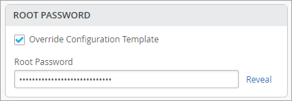
組織レベルのスイッチテンプレートがサイトに割り当てられている場合、サイト設定は表示専用モードで表示されます。テンプレートの設定を保持することも、調整することもできます。ページの各セクションで、 設定テンプレートの上書き を選択し、変更を入力できます。これらの変更は、テンプレートには適用されず、このサイトにのみ適用されます。
次の例は、テンプレートを上書きし、サイト固有の root パスワードを設定する方法を示しています。
-
サイト変数による設定をサポートするフィールドには、その横に VAR ラベルがあり、その下にサイト変数の形式を示すヘルプテキストがあります。サイト変数を使用して設定されたフィールドの場合、解決済み値がそのフィールドの下に表示されます。サイト変数を設定するには、「 サイト変数の設定」に記載されている手順に従います。
-
スイッチを設定する際は、「 スイッチ設定のベストプラクティス」 に従うことを推奨します。
組織レベルとサイトレベルの両方で、スイッチ設定は以下に説明するようにセクションにグループ化されます。
すべてのスイッチ構成
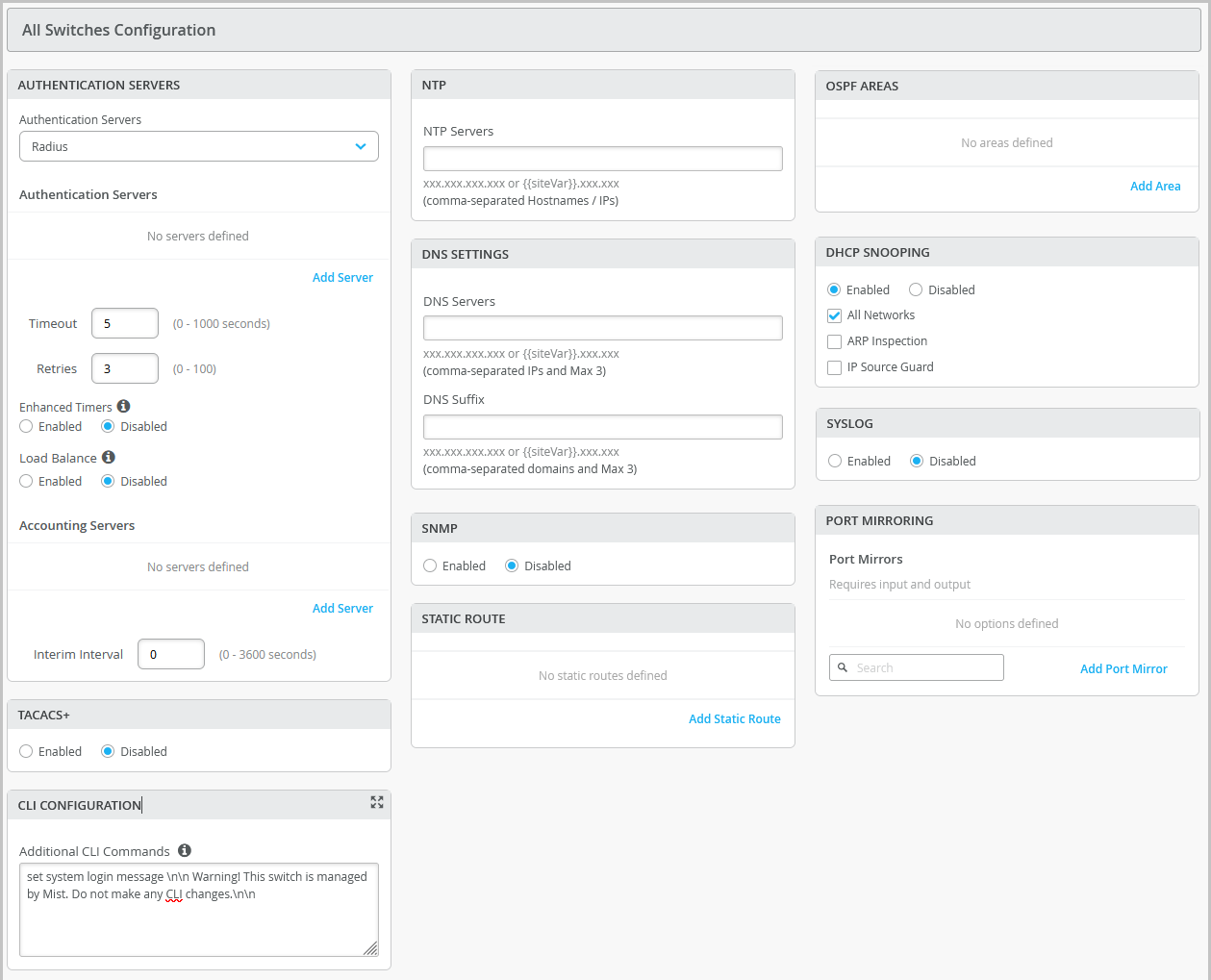
Configure these options in the All Switches section of the Organization > Switch Templates page and the Site > Switch Configuration page.
| Field/Section | Description |
|---|---|
| AUTHENTICATION SERVERS | Choose an authentication server for validating usernames and passwords, certificates, or other authentication factors provided by users.
After selecting an authentication server, configure additional details for the selected server as required. You can configure information that include:
Note:
If you want to set up RADIUS authentication for Switch Management access (for the switch CLI login), you need to include the following CLI commands in the Additional CLI Commands section in the template: set system authentication-order radius set system radius-server radius-server-IP port 1812 set system radius-server radius-server-IP secret secret-code set system radius-server radius-server-IP source-address radius-Source-IP set system login user remote class class For RADIUS or TACACS+ local authentication to the Switch, it is necessary to create a remote user account or a different login class. To use different login classes for different RADIUS-authenticated users, create multiple user templates in the Junos OS configuration by using the following CLI commands in the Additional CLI Commands section: set system login user RO class read-only set system login user OP class operator set system login user SU class super-user set system login user remote full-name "default remote access user template" set system login user remote class read-only |
| TACACS+ | Enable TACACS+ for centralized user authentication on network devices. To use TACACS+ authentication on the device, you must configure information about one or more TACACS+ servers on the network. You can also configure TACACS+ accounting on the device to collect statistical data about the users logging in to or out of a LAN and send the data to a TACACS+ accounting server. In addition, you can specify a user role for TACACS+ authenticated users within switch configuration. The following user roles are available: None, Admin, Read, Helpdesk. When the TACACs+ authenticated users do not have a user account configured on the local device, Junos assigns them a user account named 'remote' by default. The port range supported for TACACS+ and accounting servers is 1 to 65535.
Note:
For TACACS+ to authenticate into the Switch, a similar login user as defined in the RADIUS section above needs to be created. |
| NTP | Specify the IP address or hostname of the Network Time Protocol (NTP) server. NTP is used to synchronize the clocks of the switch and other hardware devices on the Internet. |
| DNS SETTINGS | Configure the domain name server (DNS) settings. You can configure up to three DNS IP addresses and suffixes in comma separated format. |
| SNMP | Configure Simple Network Management Protocol (SNMP) on the switch to support network management and monitoring. You can configure the SNMPv2 or SNMPv3. Here are the SNMP options that you can configure:
For more information, see Configure SNMP on Switches. |
| STATIC ROUTE | Configure static routes. The switch uses static routes when:
Mist supports IPv4 and IPv6 addresses for static routes. The IPv6 support is available for destination and next hop addresses. Types of static routes supported:
After specifying the details, click the check mark (✓) on the upper right of the Add Static Route window to add the configuration to the template. |
| CLI CONFIGURATION | To configure any additional settings that are not available in the template's GUI, you can use set CLI commands. For instance, you can set up a custom login message to display a warning to users, advising them not to make any CLI changes directly on the switch. Here's an example of how you can do it: set system login message \n\n Warning! This switch is managed by Mist. Do not make any CLI changes. To delete a CLI command that was already added, use the delete system login message \n\n Warning! This switch is managed by Mist. Do not make any CLI changes.
Note:
Ensure that you enter the complete CLI command for the configuration to be successful. If configurations entered using CLI commands contain errors, a warning appears on the switch details page (Switches > Switch Name). For more information, refer to Add or Delete a CLI Configuration. |
| OSPF | From this tile, you can:
For more information on how to configure OSPF through Mist, refer to OSPF Configuration for Switches. |
| VRRP | From this tile you can add a VRRP group by assigning a group number, authentication type, and network(s). For more information, see Add a VRRP Group to a Configuration. |
| DHCP SNOOPING | Juniper EX series and QFX series switches provide excellent port security, including DHCP snooping, Address Resolution Protocol (ARP) inspection, and IP Source Guard. You can enable these options for all or selected VLANs on the switch from the Mist portal. DHCP snooping must be enabled for DHCP issues to be included in the Wired Successful Connect SLE. DHCP Snooping monitors DHCP messages from untrusted devices connected to the switch. When enabled, DHCP snooping extracts the IP address and lease information from the DHCP packets and stores it in a snooping database. Port security on the EX switches uses this information to verify DHCP requests and block DHCPOFFERs received on untrusted ports (DHCP DISCOVER and DHCP REQUEST are not affected).
By default, the DHCP protocol considers all trunk ports as trusted and all access ports as untrusted. We recommend that you only connect a DHCP server to the switch using a trunk port, or, if you must use an access port, be sure to explicitly configure that port as trusted in the port profile or DHCP will not work. Note that if you connect a device configured with a static IP address to an untrusted port on the switch, the MAC-IP binding may not exist in the DHCP snooping database; the packets will be dropped. You can use this command |
| SYSLOG | Configure SYSLOG settings to set up how system log messages are handled. You can configure settings to send the system log messages to files, remote destinations, user terminals, or to the system console. For help with the configuration options, see Configure the System Log. |
| PORT MIRRORING |
Configure port mirroring. Port mirroring is the ability of a router to send a copy of a packet to an external host address or a packet analyzer for analysis. Mist supports both local and remote port mirroring. In local port mirroring, the source ports and the destination ports (monitor port) are located on the same network switch. In remote port mirroring, the source ports and destination ports are not on the same switch. In this case, the source port forwards the packet copy to the remote destination port through the connection achieved by the ports between the two switches. In the port mirroring configuration, you can specify the following:
|
| Routing Policy |
Configure routing policies for the entire organization (Organization > Switch Templates) or for a site (Site > Switch Configuration). Configuration involves defining terms, which consist of match conditions and actions to apply to matching routes. A routing policy framework is composed of default rules for each routing protocol. These rules determine which routes the protocol places in the routing table and advertises from the routing table. Routing policies are tied to protocols such as BGP or OSPF. A routing policy will only be pushed to the switch configuration if it is tied to the BGP Routing Protocol. The routing policies that are already defined inside the BGP tab of a switch will appear on the Routing Policy tab. To configure a routing policy:
|
管理
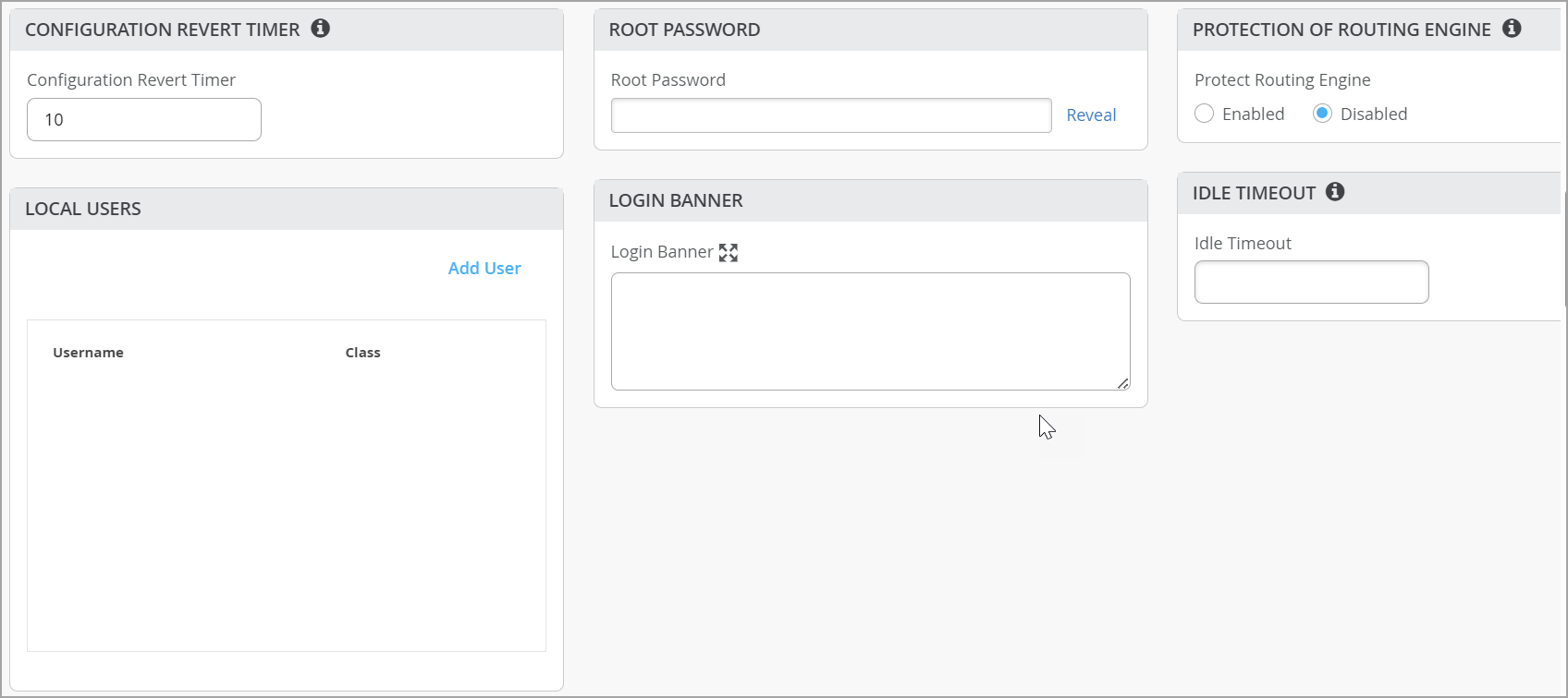
Configure these options in the Management section of the Organization > Switch Templates page and the Site > Switch Configuration page.
| Option | Notes |
|---|---|
| Configuration Revert Timer |
This feature helps restore connectivity between a switch and the Mist cloud if a configuration change causes the switch to lose connection. It automatically reverts the changes made by a user and reconnects to the cloud within a specified time duration. By default, this time duration is set to 10 minutes for EX Series switches. You can specify a different time duration. Range: 3 to 30 minutes. In case of a configuration revert event, you can check the switch events page to get specific insight into why the switch configuration was reverted. |
| Root Password |
A plain-text password for the root-level user (whose username is root). |
| Protection of Routing Engine |
Enable this feature to ensure that the Routing Engine accepts traffic only from trusted systems. This configuration creates a stateless firewall filter that discards all traffic destined for the Routing Engine, except packets from specified trusted sources. Protecting the Routing Engine involves filtering incoming traffic on the router’s lo0 interface. Enabling Protection of Routing Engine on Juniper Switches is suggested as the best practice. When Protection of Routing Engine is enabled, Mist by default ensures that the following services (if configured) are allowed to communicate with the switch: BGP, BFD, NTP, DNS, SNMP, TACACS, and RADIUS. If you need additional services that need access to the switch, you can use the Trusted Networks or Services section. If you want to set up access to the switch via ssh, select the ssh option under Trusted Services. If you need to allow switch to respond to pings, select the icmp option under Trusted Services. If you have other segments that you would like to reach the switch from, you can add them under Trusted Networks or Trusted IP/Port/Protocol. For more information, refer to Example: Configuring a Stateless Firewall Filter to Accept Traffic from Trusted Sources and Example: Configuring a Stateless Firewall Filter to Protect Against TCP and ICMP Floods. |
| Local Users |
Create a local user account on the switch for device management purposes. To create a user account, click Add User and then define a username, login class (Operator, Read-only, Super User, or Unauthorized), and a password. |
| Idle Timeout |
The maximum number of minutes that a remote shell session can be idle. When this limit is reached, users are logged out. (Valid Range: 1-60). |
| Login Banner |
Enter text that you want users to see when they log in to the switch. Example: “Warning! This switch is managed by Juniper Mist. Do not make any CLI changes.” You can enter up to 2048 characters. |
| DHCP Option 81 (For Dynamic DNS) |
Enable switches with DHCP option 81 support. When this option is enabled on a switch, the clients connected to that switch can send their fully qualified domain name (FQDN) to the DHCP server while requesting an IP address. This allows the DHCP server to update DNS records accordingly. You can enable the DHCP option 81 at the site level (Site > Switch Configuration) and device level (Switches > Switch Name) as well. |
| Switch Timezone |
Enable the Use Site Timezone option to configure the switch to automatically align its time zone with the associated site’s configured time zone. When this option is enabled and saved, the effective time zone is displayed on both the site and switch detail pages and is pushed to the device. If Use Site Timezone is disabled, the switch defaults to UTC. Note that the switch time zone configured via the additional CLI commands takes precedence over the time zone configured using the Use Site Timezone option. This configuration is available at the organization or site level and at the switch level. |
共有要素
共有要素—ネットワーク
このセクションでは、ポートプロファイルで使用できるVLANを追加または更新できます。
VLAN ごとに、名前、VLAN ID、サブネットを入力します。サブネットにIPv4またはIPv6アドレスを指定できます。その他のヒントについては、画面の情報を参照してください。
このタイルには、ユーザー定義のポートプロファイルまたはL3サブインターフェイスで使用されていないネットワークを非表示にするオプションがあります。この機能により、使用中のネットワークと使用されていないネットワークをすばやく特定できます。
共有要素—ポートプロファイル
プロファイルに関する一般的な情報については、 静的および動的ポートプロファイルを参照してください。
サイトレベルで作業している場合、ポートプロファイル名の横にアスタリスク(*)が表示されることがあります。これらのポートプロファイルは、スイッチテンプレートで作成されています。これらをクリックすると、表示専用モードで設定が表示されます。サイト固有の変更(スイッチテンプレート自体には影響せず、このサイトのみに影響を与える)を行うには、[ テンプレート定義済みプロファイルを上書きする ]を選択し、設定を編集します。
プロファイルを追加をクリックしてポートプロファイルを設定し、フィールドの説明については以下の表を参照してください。
| オプション | 注記 |
|---|---|
| 名前、ポート有効化、説明 | ポートを識別して有効にするための基本設定 |
| モード |
|
| ポートネットワーク(タグなし/ネイティブVLAN) | ポートネットワークまたはネイティブVLANを指定します。 |
| VoIPネットワーク | VoIPネットワークを指定します(該当する場合)。 |
| トランクネットワーク | トランクモードを選択した場合は、トランクネットワークを指定します。すべてまたは特定のネットワークを選択できます。 |
| dot1x認証を使用する | ポートベースのネットワークアクセス制御用のIEEE 802.1X認証を有効にするには、このオプションを選択します。802.1X認証は、プライベートVLAN(PVLAN)のメンバーであるインターフェイスでサポートされています。 ポートでdot1x認証を有効にした場合、以下のオプションが利用可能になります。
dot1x認証を機能させるには、以下も行う必要があります。
|
| スピード |
デフォルト設定の「自動」を維持するか、速度を選択します |
| デュプレックス |
デフォルト設定の「自動」を維持するか、「ハーフ」または「フル」を選択します。 |
| MAC制限 | インターフェイスによって動的に学習できるMACアドレスの最大数を設定します。インターフェイスが設定されたMAC制限を超えると、フレームをドロップします。MAC制限もログエントリーになります。設定された値は、置換またはクリアされるまでアクティブなままで、デバイスの再起動後も維持されます。 デフォルト値:0 サポートされている範囲:0〜16383 |
| PoE | パワーオーバーイーサネット(PoE)をサポートするポートには、次のオプションを含めることができます。
スイッチページのインターフェイスアイコンにマウスを合わせると、以下のPoEステータス情報が表示されます。
|
| VLAN STPごと | VLANスパニングツリープロトコル(VSTP)またはVLAN単位のスパニングツリーでスイッチを設定します。VSTPは、VLAN単位でレイヤー2ネットワークのループを防止するのに役立ちます。VLANごとに1つのスパニングツリーにより、きめ細かいロードバランシングが可能になります。Mistでは、デフォルトでVLAN単位のスパニングツリーが動作する他のベンダーのデバイス(Ciscoなど)に対して、この機能を有効にすることを推奨しています。 この設定は、サイトレベルとスイッチレベルでも使用できます。 |
| STPエッジ | ポートでBPDU(ブリッジプロトコルデータユニット)ガードを有効にする場合は、ポートをSTP(スパニングツリープロトコル)エッジポートとして設定します。STPエッジは、STPに参加していないクライアントが接続されているポートで有効になります。この設定により、ポートがエッジポートとして扱われ、BPDUの受信を防止されます。STP Edgeで設定されたポートに非エッジデバイスを接続すると、ポートは無効になります。さらに、スイッチインサイトページでは、ポートBPDUブロックイベントが生成されます。 スイッチの詳細 のフロントパネルにも、このポートのBPDUエラーが表示されます。 フロントパネルでポートを選択し、[ BPDU エラーのクリア(Clear BPDU Errors)] をクリックすると、BPDU エラーのポートをクリアできます。 アップリンクポートでSTPエッジを有効にしないでください。 スイッチの詳細ページのポートプロファイルセクションから、スイッチレベルでSTPエッジを設定することもできます。 |
| STPポイントツーポイント |
この設定により、インターフェイスモードがポイントツーポイントに変更されます。ポイントツーポイントリンクは、1つのポートを別のポートに接続する2つのネットワークノードまたはスイッチ間の専用リンクです。 |
| STPルートポートなし |
この設定では、インターフェイスがルートポートになるのを防ぎます。 |
| STP BPDUのブロック |
通常、BPDUが想定されないエッジポートまたはアクセスポートで有効になります。このオプションを有効にすると、BPDUを受信するとポートが直ちにシャットダウンされるため、ループや設定ミスを防ぐことができます。 STPエッジが有効になっている場合、STP BPDUのブロックは自動的に無効になります。ただし、BPDUライブ性チェックは引き続き設定できます。STP BPDUのブロックが有効になっている場合、STPエッジとBPDUライブ性チェックの両方が自動的に無効になります。 |
| STP BPDUライブ性チェック | 通常、BPDUが想定されるアップリンクまたはトランクポートで有効になります。この機能は、BPDUの受信を監視し、ポートをブロックし、20秒以内にBPDUを受信しない場合にアラームを発生させるため、障害や設定ミスを迅速に検知できます。 |
| QoS | ポートのサービス品質(QoS)を有効にして、音声などの遅延の影響を受けやすいトラフィックを、ポート上の他のトラフィックよりも優先します。
注:
最適な結果を得るには、ダウンストリーム(受信)とアップストリーム(発信)トラフィックの両方でサービス品質(QoS)を有効にすることが重要です。これにより、ネットワークが双方向のトラフィックを効果的に優先して管理できるようになり、パフォーマンスが向上し、全体的なサービス品質が向上します。 WLAN設定ページ(サイト>WLAN>WLAN名)でQoS設定を上書きするオプションがあります。QoS設定を上書きするには、QoSを上書きチェックボックスを選択し、無線アクセスクラスを選択します。ダウンストリームトラフィック(>クライアントAP)は、指定されたオーバーライドアクセスクラス値でマークされます。上書き設定は、アップストリームトラフィック(クライアント>AP)をサポートしていません。 「 QoS設定」も参照してください。 |
| ストーム制御 | ストーム制御を有効にしてトラフィックレベルを監視し、トラフィックがトラフィックレベル(パーセンテージで指定)を超えた場合、ブロードキャスト、マルチキャスト、不明なユニキャストパケットを自動的にドロップします。この指定されたトラフィックレベルは、ストーム制御レベルと呼ばれます。この機能は、パケットの増殖を積極的に防止し、LANのパフォーマンスを維持します。 ストーム制御を有効にすると、ブロードキャスト、マルチキャスト、不明なユニキャストパケットを監視から除外することもできます。 また、トラフィックがユーザー定義のストーム制御しきい値を超えた場合に、ポートを自動的にシャットダウンするようにスイッチを設定することもできます。しきい値に対するアクションの下にある シャットダウンポート チェックボックスを選択します。 詳細については、「 ストーム制御について」を参照してください。 |
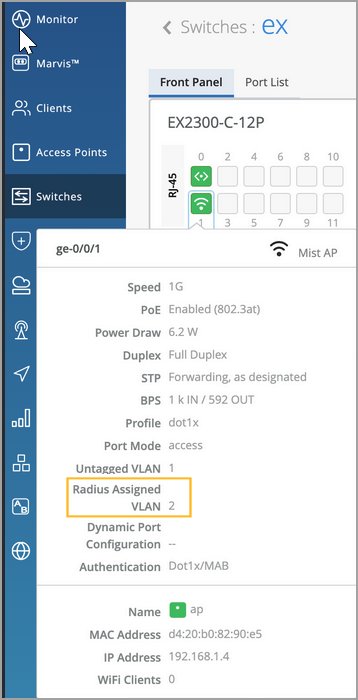
| 永続的(スティッキー)MAC 学習 | デバイスの再起動後も、 永続(スティッキー)MAC を有効にすると、インターフェイスによって学習された信頼できるワークステーションとサーバーのMACアドレスが保持されます。静的有線クライアント用にスティッキーMACを設定できます。スティッキーMACは、ジュニパー Mist APインターフェイスでの使用を意図しておらず、トランクポートや802.1X認証で設定されたポートでもサポートされていません。 MAC制限(前述)と組み合わせて使用すると、スティッキーMACは、レイヤー2サービス拒否(DoS)攻撃、イーサネットスイッチングテーブルに対するオーバーフロー攻撃、DHCPスターベーション攻撃から保護すると同時に、インターフェイスがMACアドレスを動的に学習できるようにします。Mistポータルのインサイトページでは、これらのイベントが MAC Limit Exceeded として報告されます。 スイッチのポートプロファイルの一部として、スティッキーMACとMAC制限の両方を設定します。このビデオでは、一般的な手順について説明します。 Port profiles provide a convenient way to manually or automatically provision EX switch interfaces. Going into the EX4300, we'll first create VLANs. We'll make a camera network with VLAN ID 30 and an IoT network with VLAN ID 29. You can create as many networks as needed. You can create the profiles, for example, a camera, and map it to the camera network that we just created. Customize the settings as desired, such as PoE and STP. We'll repeat this process to create profiles for a corporate device enabling 802.1x authentication, an IoT device configured with PoE, and an access point configured as a trunk port. It's very simple to modify profiles to meet your specific requirements. Then we go into the port configuration section to associate the configurations with port profiles. Here we map ports 1 through 5 to be with an AP profile, ports 6 through 10 with a corporate device profile, ports 11 through 15 with IoT profiles, and ports 16 to 20 with the camera profile. This is how to create port profiles. We can also create port aggregation uplinks to be associated with the appropriate profiles. When you save all of your changes, this pushes the configuration to the particular switch. This covers how EX switches are manually provisioned with port profiles from the Juniper MIST Cloud. ポートプロファイル設定ブロックの下部にある 永続的(スティッキー)MAC学習 オプションを明示的に有効にして、インターフェイスに関連付けるポートプロファイルの一部としてスティッキーMACを含める必要があります。MAC制限の場合、デフォルト値は0(無制限、つまり無効)ですが、最大16383個の一意のMACアドレスを許可する値を設定することで有効にすることができます。 MistポータルでMAC制限またはMACカウントに設定されている値を確認するには、スイッチページからスイッチを選択し、スイッチポートにマウスを置きます。どの(ポート)プロファイルがインターフェイスに適用されているかを確認し、ひいてはそのスティッキーMACステータスを知ることができます。
図2:スティッキーMAC 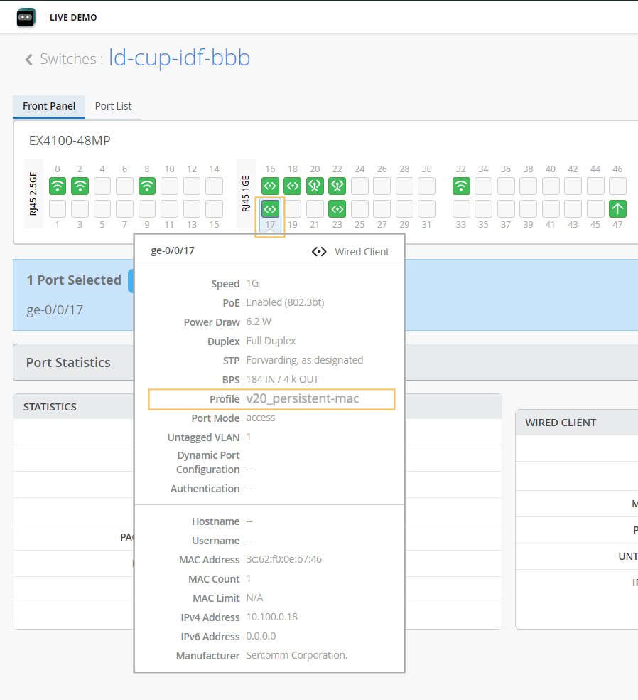 を示すポートの詳細 を示すポートの詳細
設定されたMAC制限と学習されたMACの数は、インターフェイス上での動的学習が進むにつれて、数分後に表示されます。Mistダッシュボードには、最大MACアドレス数のみが表示されます。ただし、スイッチへの リモートシェル を開き、以下のJunos CLIコマンドを実行することで、特定のインターフェイスが学習したすべてのMACアドレスを確認できます。
MACカウントは永続的な値であり、MACアドレスがクリアされるまで(またはポートプロファイルで無効になり、その設定がスイッチにプッシュされるまで)。 Mistダッシュボードから特定のインターフェイスのMACアドレスをクリアするには、ネットワーク管理者またはスーパーユーザーとしてログインする必要があります。次に、スイッチのフロントパネルから目的のポートを選択し(図1を参照)、表示される Clear MAC [Dynamic/Persistent] ボタンをクリックします。 スイッチインサイトページには、イベントが MAC Limit Reset イベントとして表示されます。 フロントパネルの詳細については、「 スイッチの詳細」を参照してください。 |
ポートプロファイルタイルでは、ユーザーが定義した静的または動的ポート設定で使用されていないポートプロファイルを非表示にするオプションがあります。この機能により、使用中のポートプロファイルと使用されていないポートプロファイルをすばやく特定できます。
共有要素—ダイナミックポート設定
ダイナミックポートプロファイリングは、接続されたクライアントデバイスの一連のデバイスプロパティを使用して、事前設定されたポートとネットワーク設定をインターフェイスに自動的に関連付けます。
ダイナミックポートプロファイル設定には、大まかに言えば以下の2つのステップが含まれます。-
動的なポートプロファイルルールを設定します(ここで説明)。
-
ダイナミックポートとして機能させるポートを指定します。これを行うには、スイッチテンプレートのスイッチの選択セクションにあるポート設定タブにあるスイッチ設定を有効にするチェックボックス、またはスイッチの詳細ページのポート設定セクションを選択します。詳細については、「スイッチ設定の選択 - ポート設定タブ」の「動的設定を有効にする」の行を参照してください。
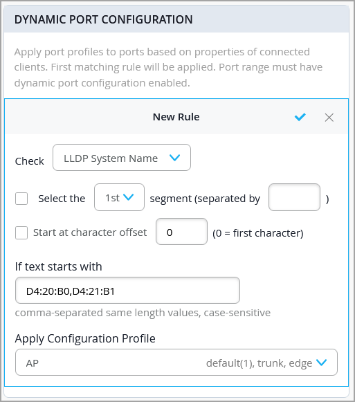
以下のパラメーターを使用して、動的なポートプロファイルルールを設定できます。
-
LLDPシステム名
-
LLDPの説明
-
LLDPシャーシID
-
RADIUSユーザー名
-
RADIUSフィルター-ID
-
MAC(イーサネットMACアドレス)
この例では、設定されたパラメータに一致するLLDPシステム名を持つ任意のデバイスに接続された場合、設定プロファイルの 適用 フィールドで指定されたポートプロファイルが、動的設定が有効になっているスイッチポートに割り当てられます。
-
DPCルールのテキストが 始まる場合 フィールドに複数の値を使用する場合は、カンマで区切り、すべての長さが同じになるようにします。長さが異なる値がある場合は、その値に対して別のルールを作成する必要があります。
-
デバイスがLLDPをサポートしている場合は、MACベースの一致よりもLLDPベースの一致を優先します。
-
802.1X認証が有効になっているポートでは、MACベースのマッチングを使用しないでください。
-
Filter-ID属性の使用は避けてください。ポートで 802.1X が有効になっている場合、VLAN 割り当てはFilter-IDに依存せずに RADIUS 経由で処理する必要があります。
詳細については、「 ダイナミックポートプロファイル割り当ての設定」を参照してください。
共有要素 - VRF
VRF を使用すると、EXシリーズ スイッチを複数の仮想ルーティング インスタンスに分割し、ネットワーク内のトラフィックを効果的に分離できます。VRF の名前を定義し、それに関連付けられたネットワークを指定し、必要な追加ルートを含めることができます。追加ルートにIPv4またはIPv6アドレスを指定できます。
-
デフォルトネットワーク(VLAN ID = 1)をVRFに割り当てることはできません。
-
Mistでは、トラフィックの分離と重複するIPアドレス空間が必要なネットワークセグメントでVRFを使用することを推奨しています。
スイッチ設定の選択
In the Select Switches Configuration section, you can create rules to apply configuration settings based on the name, role, or model of the switch.
Click an existing rule to edit it, or click Add Rule to create a new one. Then complete each tabbed page. As you enter settings, click the checkmark at the top right to save your changes. You can also create a switch rule entry by cloning an existing rule. To do that, you just need to click the clone button and name the new rule.
The various tabs are described in separate sections below.
- スイッチの設定を選択—情報タブ
- スイッチ設定の選択—ポート設定タブ
- スイッチ設定の選択—IP設定タブ
- スイッチ設定の選択—IP設定(OOB)タブ
- 選択スイッチ設定—STPブリッジ優先度
- スイッチ設定の選択—ポートミラーリングタブ
- スイッチ設定の選択—CLI設定タブ
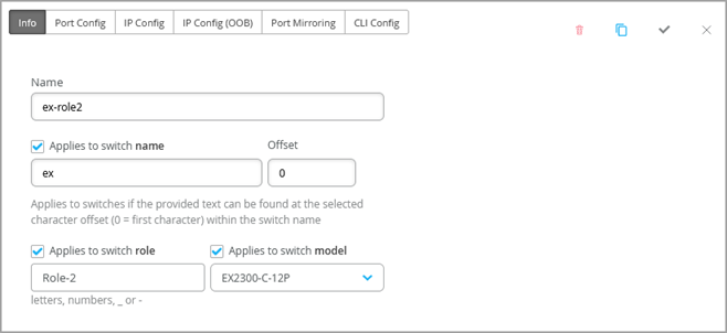
スイッチの設定を選択—情報タブ
| オプション | 注記 |
|---|---|
| 名前 |
このルールを識別するための名前を入力します。 |
| スイッチ名に適用 |
このルールを、指定した名前に一致するすべてのスイッチに適用する場合は、このオプションを有効にします。次に、テキストとオフセット文字数を入力します。たとえば、オフセットが0の abc を入力すると、名前が abcで始まるスイッチにルールが適用されます。オフセットが 5 の場合、ルールはスイッチ名の最初の 5 文字を無視します。 |
| スイッチの役割に適用されます |
このルールを同じロールを持つすべてのスイッチに適用する場合は、このオプションを有効にします。小文字、数字、アンダースコア(_)、またはダッシュ(-)を使用してロールを入力します。 |
| 適用対象: スイッチ モデル |
このルールを同じモデルを持つすべてのスイッチに適用する場合は、このオプションを有効にします。次に、モデルを選択します。 |
スイッチ設定の選択—ポート設定タブ
| オプション | 注記 |
|---|---|
| 設定リスト | ポート設定を追加をクリックするか、編集するポート設定を選択します。 |
| ポートID |
設定するポートを入力します。 |
| 設定プロファイル | 指定したポートに適用する設定プロファイルを選択します。
注:
Q-in-Qトンネリングでスイッチポートを設定する場合は、このドロップダウンリストからQ-in-Qを選択します。詳細については、「スイッチポートでのQ-in-Qトンネリングの設定」を参照してください。 |
| ポートネットワーク(S-VLAN) |
ポートがQ-in-Qトンネリングを使用している場合は、サービスVLAN(S-VLAN)を指定します。S-VLANは、顧客サイト間のレイヤー2イーサネット接続を拡張するために使用される外部の追加VLANタグです。これは、顧客のVLAN IDが重複している場合に特に役立ちます。 |
| スピード |
注:
設定プロファイルとしてQ-in-Qを選択した場合にのみ適用されます。 デフォルト設定の「自動」を維持するか、速度を選択します。 |
| デュプレックス |
注:
設定プロファイルとしてQ-in-Qを選択した場合にのみ適用されます。 デフォルト設定の「自動」を維持するか、「ハーフ」または「フル」を選択します。 |
| PoE |
注:
設定プロファイルとしてQ-in-Qを選択した場合にのみ適用されます。 ポートがPower over Ethernet(PoE)をサポートできるようにします。 |
| MTU |
注:
設定プロファイルとしてQ-in-Qを選択した場合にのみ適用されます。 ポートのメディア最大送信単位(MTU)を指定します。デフォルト: 1514。範囲:256 - 9216。 インターフェイスのメディア最大伝送単位(MTU)は、フラグメント化なしに そのインターフェイスを転送できる最大のデータ単位 です。 |
| ストーム制御 |
注:
設定プロファイルとしてQ-in-Qを選択した場合にのみ適用されます。 ストーム制御を有効にしてトラフィックレベルを監視し、トラフィックがトラフィックレベル(パーセンテージで指定)を超えた場合、ブロードキャスト、マルチキャスト、不明なユニキャストパケットを自動的にドロップします。この指定されたトラフィックレベルは、ストーム制御レベルと呼ばれます。この機能は、パケットの増殖を積極的に防止し、LANのパフォーマンスを維持します。 ストーム制御を有効にすると、ブロードキャスト、マルチキャスト、不明なユニキャストパケットを監視から除外することもできます。 また、トラフィックがユーザー定義のストーム制御しきい値を超えた場合に、ポートを自動的にシャットダウンするようにスイッチを設定することもできます。しきい値に対するアクションの下にある シャットダウンポート チェックボックスを選択します。 詳細については、「 ストーム制御について」を参照してください。 |
| 説明 | ポートの説明を入力します。 |
| 動的設定を有効にする |
(この設定は、構成プロファイルとしてQ-in-Qを選択している場合は適用されません。)
注:
動的ポート設定が有効になっているスイッチポートに接続されているが、動的ポート割り当てルールに一致しない不明なデバイスに割り当てることができる制限付きVLANおよびネットワークプロファイルが作成されていることを確認します。 スイッチポートがダイナミックポートとして機能できるようにします。デバイスがダイナミックポートに接続すると、ダイナミックポートプロファイル割り当てルールで定義された属性に基づいてポートプロファイルを自動的に受信します。これらのルールについては、共有要素 - 動的ポート設定の動的ポート設定の行で説明しています。 デバイスが属性に一致しない場合は、指定されたVLAN、理想的には制限付きVLAN(ポートプロファイル)が割り当てられます。 次の例では、ポートは動的なポート割り当てで有効になっており、制限付き VLAN が割り当てられています。この場合、接続されたデバイスが動的プロファイリング属性に一致しない場合、ルーティング不可能なVLANやゲストVLANなどの制限されたVLANに配置されます。ポートアグリゲーションで有効にされたインターフェイスは、ダイナミックポート設定をサポートしていません。 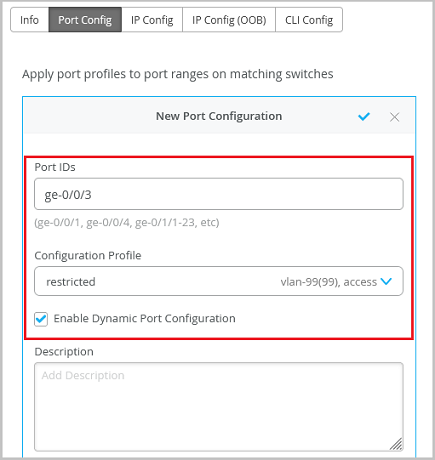 スイッチの動的ポート設定は、IoTデバイス、AP、ユーザーポートエンドポイントへの接続を確立するためのものです。 詳細については、「 ダイナミックポートプロファイル割り当ての設定」を参照してください。 |
| アップ/ダウンポートアラート |
この機能を有効にすると、ジュニパー Mistはこれらのポートのアップ状態とダウン状態間の遷移を監視します。この機能を有効にした場合は、モニター>アラート設定ページのクリティカルスイッチポートアップ>ダウンも有効にします。 |
| ポートアグリゲーション |
注:
設定プロファイルとしてQ-in-Qを選択している場合は適用されません。 この機能を有効にすると、指定されたイーサネットインターフェイスがグループ化され、単一のリンク層インターフェイスが形成されます。このインターフェイスは、リンクアグリゲーショングループ(LAG)またはバンドルとも呼ばれます。 LAGにグループ化できるインターフェイスの数と、スイッチがサポートするLAGの総数は、スイッチモデルによって異なります。LAG は、LACPを有効にしたかどうかに関わらず使用できます。もう一方のデバイスが LACP をサポートしていない場合、ここで LACP を無効にできます。 以下も指定できます。
Wired アシュアランスでLAG(リンクアグリゲーショングループ)を設定する方法については、以下のビデオをご覧ください。 |
| スイッチポート運用担当者にポートプロファイルの変更を許可する |
この機能を有効にすると、スイッチポート運用者管理者ロールを持つユーザーがこの設定を表示および管理できるようになります。 |
スイッチ設定の選択—IP設定タブ
| オプション | 注記 |
|---|---|
| ネットワーク(VLAN)リスト |
インバンド管理トラフィック用のネットワークを選択します。または、 ネットワークを追加 をクリックし、この表の残りの行の説明に従って新しいネットワークフィールドに入力します。 |
| 名前 |
このネットワークを識別するための名前を入力します。 |
| VLAN ID |
1〜4094のVLAN IDを入力するか、サイト変数を入力してIDを動的に入力します。 |
| サブネット |
サブネットまたはサイト変数を入力します。 |
スイッチ設定の選択—IP設定(OOB)タブ
| オプション | 注記 |
|---|---|
| 専用管理VRF | 専用管理VRF(帯域外)を有効または無効にします。Junosバージョン21.4以降を実行しているすべてのスタンドアロンデバイスまたはバーチャルシャーシにおいて、この機能は管理インターフェイスをデフォルト以外のVRF(仮想ルーティングおよび転送)インスタンスに限定します。管理トラフィックが、他の制御トラフィックやプロトコルトラフィックとルーティングテーブルを共有する必要がなくなりました。 |
選択スイッチ設定—STPブリッジ優先度
スイッチテンプレート(組織)レベルで ブリッジの優先度 を設定します。この設定は、サイトレベルとデバイスレベルの両方で上書きできるため、柔軟性が向上します。
追加のCLIコマンドを使用して設定されたブリッジ優先度は、UIで選択した値よりも優先されます。
スイッチ設定の選択—ポートミラーリングタブ
このタブには、すでに追加されているポートミラーリング設定のリストが表示されます。エントリをクリックして編集します。または、 ポートミラーを追加 をクリックして、ポートミラーリングを有効にします。この機能を使用すると、ルールで指定されたスイッチの役割、スイッチ名、スイッチモデルなどのパラメーターに基づいて、スイッチにポートミラーリングを動的に適用できます。この機能は通常、監視とトラブルシューティングに使用されます。ポートミラーリングが有効になっている場合、スイッチはミラーリングされたポートからモニターポートにネットワークパケットのコピーを送信します。
Mistは、ローカルポートミラーリングとリモートポートミラーリングの両方をサポートしています。ローカルポートミラーリングでは、送信元ポートと宛先ポート(モニターポート)が同じネットワークスイッチ上に配置されます。リモートポートミラーリングでは、送信元ポートと宛先ポートが同じスイッチ上にありません。この場合、送信元ポートは、2 つのスイッチ間のポートによって実現される接続を介して、パケット コピーをリモート宛先ポートに転送します。
構成オプションには、以下が含まれます。
-
入力—監視するトラフィックの送信元(インターフェイスまたはネットワーク)。入力とともに、Mistがインターフェイスのイングレストラフィックとエグレストラフィックのどちらを監視するかを指定できます。イングレストラフィックとエグレストラフィックの両方を監視する場合は、同じインターフェイスに2つの入力エントリを追加します。1つはイングレスフラグ、もう1つはエグレスフラグを追加します。
-
出力—トラフィックをミラーリングする宛先。インターフェイス、ネットワーク、またはIPアドレスを指定できます(リモート宛先の場合)。入力フィールドと出力フィールドの両方に同じインターフェイスまたはネットワークを指定することはできません。
スイッチ設定の選択のルールは、グローバルポートミラーリング設定よりも優先されます。また、グローバルポートミラーリングが設定されている場合は、スイッチ設定の選択セクションにデフォルトのルールとして表示され、読み取り専用として表示されます。グローバルレベルで編集できます。
スイッチ設定の選択—CLI設定タブ
このセクションでは、テンプレートのGUIでは使用できない追加設定を構成するには、set CLIコマンドを使用できます。
例えば、カスタムログインメッセージを設定して、スイッチ上で直接CLIを変更しないように警告をユーザーに表示することができます。その方法の例を次に示します。
set system login message \n\n Warning! This switch is managed by Mist. Do not make any CLI changes.
すでに追加されているCLIコマンドを削除するには、次の例のように delete コマンドを使用します。
delete system login message \n\n Warning! This switch is managed by Mist. Do not make any CLI changes.
スイッチポリシーラベル、GBPタグ、およびスイッチポリシー
Use this section to create Access Control Lists (ACLs) (also known as firewall filters) and Group-Based Policies (GBP).
-
Source/Destination labels—Create labels to identify the source/destination IP addresses for Access Control List (ACL) policies (RADIUS-based firewall filters). For more information, see Switch Policies.
-
GBP tags—Create tags for Group-Based Policies (GBP), which leverage VXLAN technology. GBP simplifies configuration and provides endpoint access control across your campus. For more information, see Group-Based Policies.