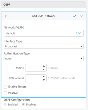
OSPF Configuration for Switches
Follow these steps and example to configure OSPF at the organization and site level.
OSPF is an interior gateway protocol (IGP) that routes packets within a single autonomous system (AS). OSPF uses link-state information to make routing decisions, making route calculations using the shortest-path-first (SPF) algorithm (also referred to as the Dijkstra algorithm). Each router running OSPF floods link-state advertisements throughout the AS or area that contain information about that router’s attached interfaces and routing metrics. Each router uses the information in these link-state advertisements to calculate the least cost path to each network and create a routing table for the protocol.
You can also include routing policies (import and export policies) in OSPF configurations at the switch level. The routing policy is composed of terms. Each term can include a set of conditions and a then statement, which defines the actions to take if an OSPF route matches the conditions specified in the term.
Junos OS supports OSPF version 2 (OSPFv2) and OSPF version 3 (OSPFv3), including virtual links, stub areas, and for OSPFv2, authentication. Junos OS does not support type-of-service (ToS) routing.
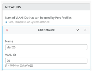
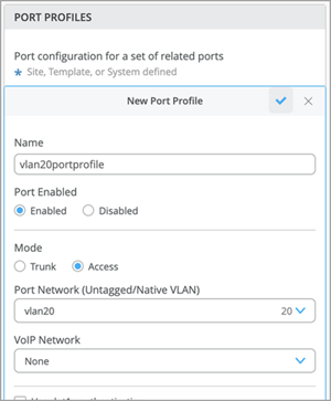
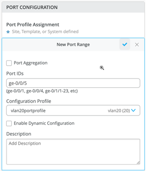
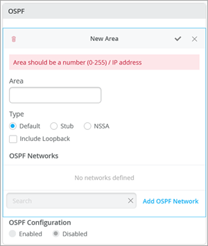
Example: Configure Basic OSPF in two EX Devices
To configure OSPF in a switch (configure these steps in both the switches):
CLI Commands
When Interface Type is p2p and Authentication Type is md5:
"set apply-groups top"
"set groups default interfaces <*> unit 0 family ethernet-switching vlan members [ default ]",
"set groups top forwarding-options storm-control-profiles default all",
"set groups top interfaces lo0 unit 0 family inet address 11.1.1.1/32",
"set groups top poe interface all",
"set groups top protocols ospf area 0 interface irb.20 authentication md5 1 key $9$cxXyK8ws...",
"set groups top protocols ospf area 0 interface irb.20 interface type p2p"
"set groups top routing-options router-id 11.1.1.1",
When Interface Type is p2p and Authentication Type is none:
"set apply-groups top"
"set groups default interfaces <*> unit 0 family ethernet-switching vlan members [ default ]",
"set groups top forwarding-options storm-control-profiles default all",
"set groups top interfaces lo0 unit 0 family inet address 11.1.1.1/32",
"set groups top poe interface all",
"set groups top protocols ospf area 0 interface irb.20 interface type p2p"
"set groups top routing-options router-id 11.1.1.1",
When Interface Type is p2p and Authentication Type is password:
"set apply-groups top"
"set groups default interfaces <*> unit 0 family ethernet-switching vlan members [ default ]",
"set groups top forwarding-options storm-control-profiles default all",
"set groups top interfaces lo0 unit 0 family inet address 11.1.1.1/32",
"set groups top poe interface all",
"set groups top protocols ospf area 0 interface irb.20 authentication simple-password $9$cxXyK8ws...",
"set groups top protocols ospf area 0 interface irb.20 interface type p2p"
"set groups top routing-options router-id 11.1.1.1",
When Interface Type is p2mp and Authentication Type is md5:
"set apply-groups top"
"set groups default interfaces <*> unit 0 family ethernet-switching vlan members [ default ]",
"set groups top forwarding-options storm-control-profiles default all",
"set groups top interfaces lo0 unit 0 family inet address 11.1.1.1/32",
"set groups top poe interface all",
"set groups top protocols ospf area 0 interface irb.20 authentication md5 1 key $9$cxXyK8ws...",
"set groups top protocols ospf area 0 interface irb.20 interface type p2mp"
"set groups top routing-options router-id 11.1.1.1",
When Interface Type is p2mp and Authentication Type is none:
"set apply-groups top"
"set groups default interfaces <*> unit 0 family ethernet-switching vlan members [ default ]",
"set groups top forwarding-options storm-control-profiles default all",
"set groups top interfaces lo0 unit 0 family inet address 11.1.1.1/32",
"set groups top poe interface all",
"set groups top protocols ospf area 0 interface irb.20 interface type p2mp"
"set groups top routing-options router-id 11.1.1.1",
When Interface Type is p2mp and Authentication Type is password:
"set apply-groups top"
"set groups default interfaces <*> unit 0 family ethernet-switching vlan members [ default ]",
"set groups top forwarding-options storm-control-profiles default all",
"set groups top interfaces lo0 unit 0 family inet address 11.1.1.1/32",
"set groups top poe interface all",
"set groups top protocols ospf area 0 interface irb.20 authentication simple-password $9$cxXyK8ws...",
"set groups top protocols ospf area 0 interface irb.20 interface type p2mp"
"set groups top routing-options router-id 11.1.1.1",
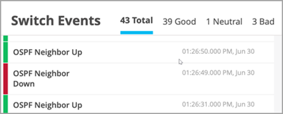
OSPF Events
The following image shows examples of OSPF events:
Configure OSPF at the Organization Level
To configure OSPF at the organization template level:
- Click Organization > Switch Templates.
- Open the organization template you want to modify.
- Navigate to the OSPF tile and click Add Area.
- Follow the steps listed in Example: Configure Basic OSPF in two EX Devices.
Configure OSPF at the Site Level
To configure OSPF at the site template level:
- Click Site > Switch Configuration.
- Open the site template you want to modify.
- Navigate to the OSPF tile and click Add Area.
- Follow the steps listed in Example: Configure Basic OSPF in two EX Devices.

