Configure Switches Using Templates
Follow these steps to use templates to configure your switches with the exact features and settings that you need for the users at your sites.
We recommend that all switches in an organization be managed exclusively through the Juniper Mist cloud, and not from the device’s CLI.
The recommended approach to configuring multiple switches with Juniper Mist™ Wired Assurance involves two main steps:
Creating a switch configuration template.
Applying the template to one or multiple sites.
The configuration settings linked to a particular site will be applied to the switches (both newly added and existing switches) within that site. This allows you to manage and apply consistent and standardized configurations across your network infrastructure, making the configuration process more efficient and streamlined.
You can also configure switches individually (without using the template) from the Switch Details page.
For a quick overview of the switch templates, watch the following video:
Juniper Mist Wired Assurance makes day-one configurations simple yet powerful. The templates can be configured at an org level, site level, or a specific switch. Navigate to Organization and Switch Templates.
We'll use prod-template in this example. The first template configures the RADIUS and NTP servers at the org level, or for all the switches in the network. The Shared Elements configuration is shared among the switches.
This is where you can create specific IoT, corporate, or camera networks mapped to VLAN IDs. You can create port profiles for camera devices, customizing PoE settings, assigning networks, and speed negotiation. Once the configuration is set, it's time to apply the template.
Let's save this as test-rule and apply it to switches assigned with an access rule. Or you can apply the rules to particular switch models. The templates also allow you to apply port profiles to port ranges in all the switches assigned to a site.
For example, port 4 is for access points, and port 5 is for IoT devices. Now the template can be applied to a site. At primary site, you can see all the inherited configuration that we just set at a global level.
These templates are simple yet flexible, meaning that you can override the global configurations at an organization, site, or switch level. If we click into the EX2300, you see that it has inherited the config defined by the global templates. You can also choose to override template settings, changing it from 4.4.2.2 to time.google.com. This switch has also inherited all the networks, port profiles, and switch configurations.
The templates make the initial setup easy and can also adapt to specific site or switch settings as needed. You can also click into the port icons to change the configurations as needed for a single or multiple ports. Whether you configure templates and profiles for one site or thousands of sites, you can scale with consistency and commonality with ease.
To configure a switch, you need to have a Super User role assigned to you. This role grants you the necessary permissions to make changes and customize the switch settings.
We recommend following Switch Configuration Best Practices when configuring your switches.
To find out which switches are supported by Juniper Mist Wired Assurance, refer to Juniper Mist Supported Hardware.
Create a Switch Configuration Template
Switch configuration templates make it easy to apply the same settings to switches across your sites. Whether it's one site or multiple sites, you can use the template to quickly configure new switches. When you assign a switch to a site, it automatically adopts the configuration from the associated template.
Configuration done on the switch through the Mist dashboard overrides any configuration done through the device CLI. The switch details page doesn’t display any configuration changes you make directly on the switch through the switch CLI.
To create a switch configuration template:
Assign a Template to Sites
After creating a switch configuration template, you need to assign it to the relevant sites. This ensures that the configuration settings are applied to the switches within those sites. You have the flexibility to apply the template to a single site or multiple sites, depending on your specific requirements.
To assign a template to one or multiple sites:
Alternatively, you can apply a template to a site from the Site Configuration page, using the following steps:
-
Click Site > Switch Configuration.
-
Click a site from the list to open it.
-
Select a template from the Configuration Template field, and then click Save.
Configure Site-Specific Settings
Switches connected to a particular site inherit the organization-level template settings applied to that site. If required, you can customize the settings at the site level. These site-specific changes will not affect the organization-level template and will apply to all the switches in the selected site.
Unless required, do not override the settings at the site level. Use site variables, instead.
To update switch settings at the site level:
Configure Switch-Specific Settings
You need to configure certain parameters on individual switches. This can be specific to each switch and cannot be configured via the template. The switch-specific settings could include a switch name, role, management interface (out of band), and an IRB interface. You can either configure the settings manually on the individual switches, or import the settings.
- Configure Switch-Specific Settings Manually
- Configure Switch-Specific Settings Using the Bulk Upload Option
Configure Switch-Specific Settings Manually
To configure additional switch-level configuration settings manually:
Configure Switch-Specific Settings Using the Bulk Upload Option
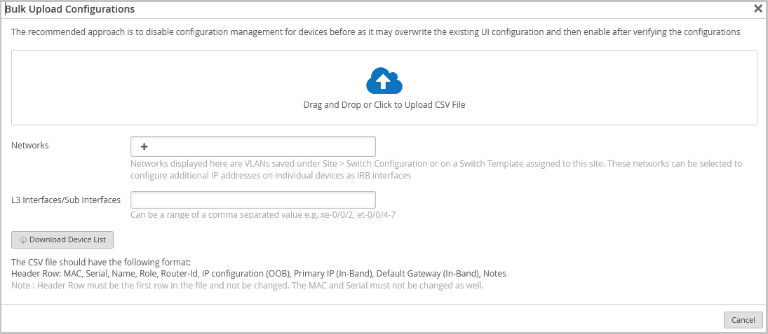
If you don't want to manually configure the switch-specific settings on each switch, you can configure the settings by uploading them through a CSV file. You can upload the settings for one or more switches at once. You can upload the following settings: MAC address, serial number, switch name, switch role, router-ID, IP configuration (OOB), Primary IP (In-Band), and Default Gateway (In-Band).
To upload the switch level settings:
-
Click Bulk Upload Configuration. The Bulk Upload
Configurations window appears.
-
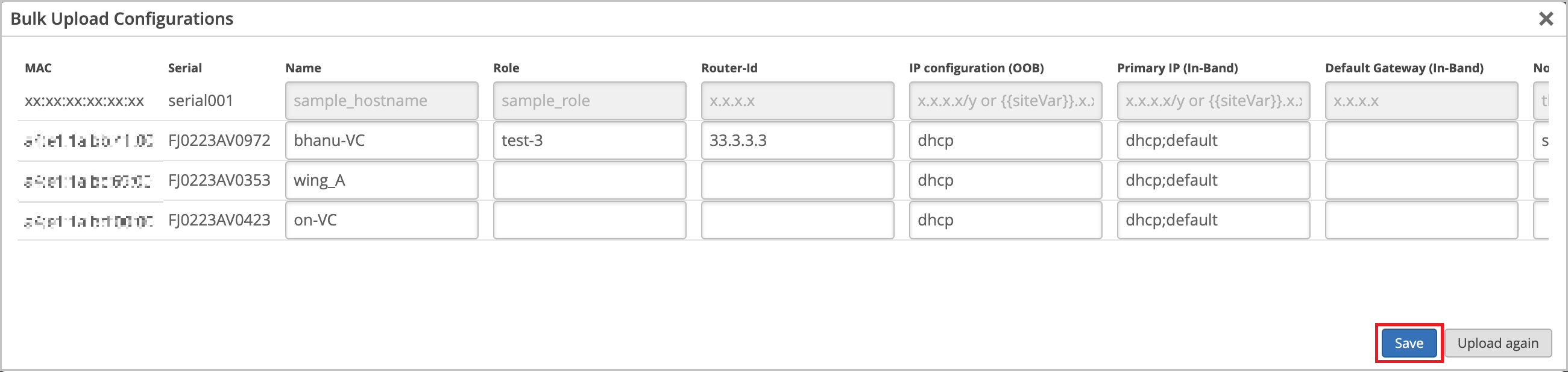
When you open the file to be uploaded from file upload window, the UI
page loads the configuration in an editable format as shown below,
 Note:
Note:-
If the CSV file does not contain information for some of the switches you selected, the configuration will not be pushed to those switches (the ones that are missing in the file).
-
If the CSV file contains information for switches you haven't selected, the configuration will not be pushed to those switches either.
-
Verify Switch Configuration
You can easily review the configuration applied to your switches and make any updates through the switch details page on the Mist portal.
To access the switch details page:
-
On the Mist portal, click the Switches tab on the left menu to open the Switches page.
-
On the List tab, click a switch to open the switch details page.
When the switch details page opens, you'll find yourself on the Front Panel tab. This tab gives you a comprehensive overview of the switch's port panel.
To check the configuration and status of a specific port, hover over that port in the front panel illustration. For instance, if you hover over port ge-0/0/45 in the following example, you'll see information indicating that a Mist AP is connected to that port. The displayed information also includes details about speed, power, the IP address, and more.
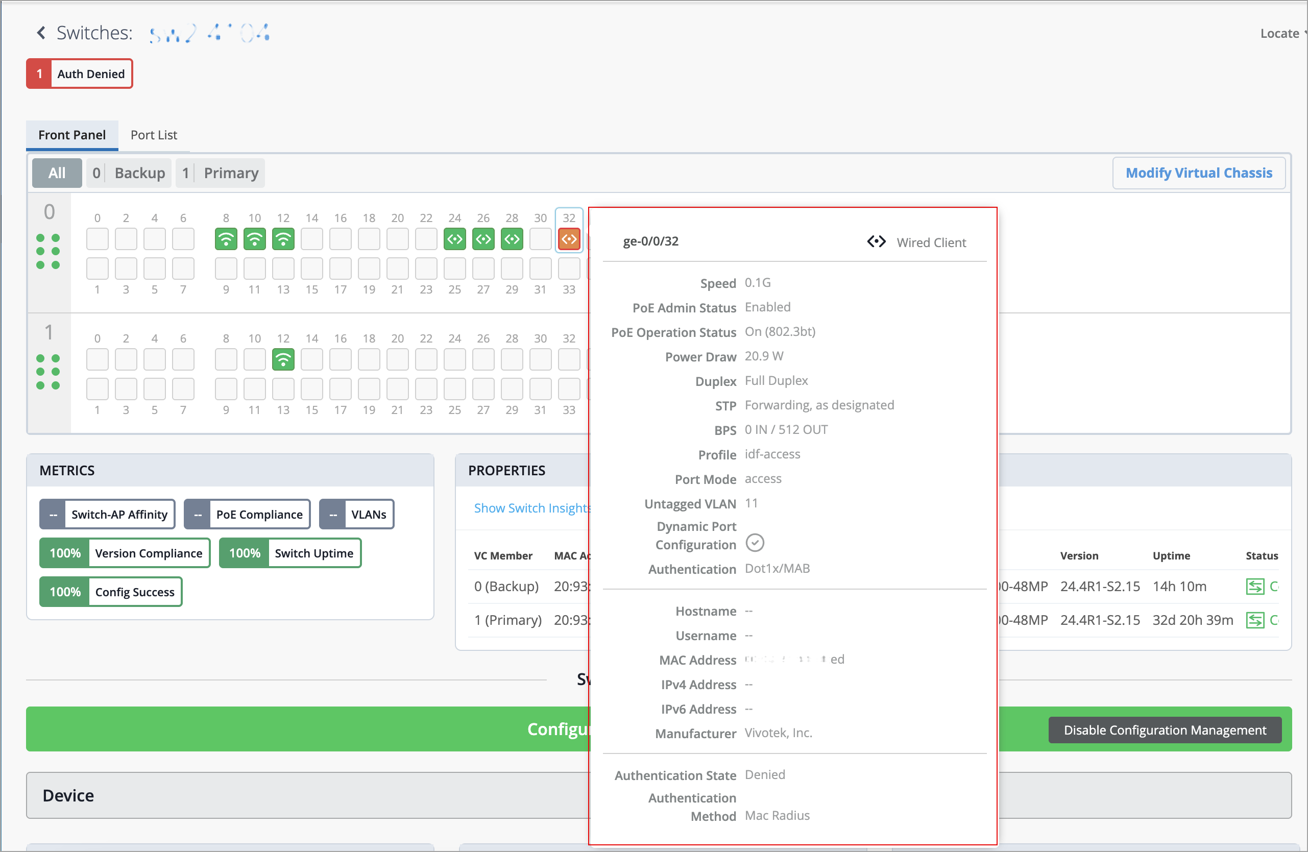
Click the port on the front panel illustration to see a more detailed view. From this view, you can perform tasks such as accessing the connected devices (for example, APs), viewing switch insights and editing the port configuration.
On the switch details page, you can also find information about switch events such as configuration changes in the Switch Insights section.
If you want to download the configuration in a text file, select the Download Junos Config option on the Utilities drop-down list on the switch details page.
To see the complete configuration applied to the switch, simply scroll down to the Switch Configuration section. From there, you can view and, if needed, edit the configuration elements.
If required, you can update the settings at the switch level, site level, or template level. You can also use CLI commands to configure features that the predefined drop-down lists and text fields on the Mist portal do not support. For more information on how to update the settings, refer to Manage or Update Configuration Settings.