
WANエッジデバイス向けの高可用性設計
この設計ガイドを使用して、Juniper Mist WAN AssuranceでWANエッジデバイスの高可用性を設定します。
WANエッジデバイスの高可用性(HA)設計は、WANエッジの導入で障害が発生した場合に、インターフェイスまたはデバイス全体が互いを引き継ぐことができるようにしたい管理者向けのものです。これは、エッジに HA WAN Edge デバイスを展開する管理者向けですが、ホワイトボックス設定用ではありません。
このドキュメントでは、ジュニパー® Mist WAN Assuranceを使用してHAハブアンドスポーク導入を設定するための手順を追ったガイダンスを提供します。これは、このガイドで参照されているハブアンドスポークトポロジーに基づいて構築されています。そのトポロジを構成したら、次の手順を使用して HA 用の WAN エッジ デバイスを設定します。
ハブアンドスポークトポロジーを設定する必要がある場合は、 WANエッジテンプレートの設定 および トラフィックステアリングを使用したハブツースポークからのパス選択の設定を参照してから、この手順に戻ります。
HAペアで使用されるデバイスハードウェアは同一である必要があります。例えば、SSR120ルーターが2台あるHAペアはHAと互換性がありますが、SSR120が1台、SSR130が1台あるHAペアは互換性がありません。
概要
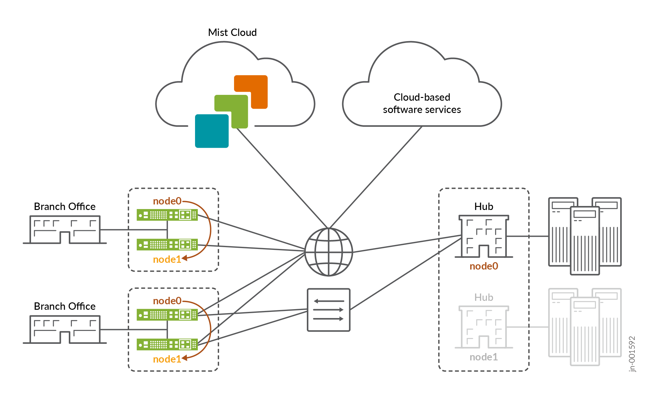
図1に示すように、高可用性のハブアンドスポークを導入します。下の図は、Juniper Mist WAN Assuranceの高可用性トポロジーを示しています。HAペアのノードは、アクティブ/スタンバイまたはアクティブ/アクティブとして実行するように設定できます。必要に応じて、HA用にハブを設定することもできます。
インターフェイス
インターフェイスは、各ノードに対して以下のパターンを使用します。
ノード0:ge-0/0/x
ノード1:ge-1/0/x
SRXデバイスについては、 SRXクラスタースロットの番号付けと論理インターフェイスの名前付けに記載されている命名パターンに従います。
SSRデバイスの場合、 SSRデバイスのデフォルトポートレイアウトにある命名パターンに従います。
HAハブ用のWANインターフェイスには、静的IPアドレスが必要です。スポークは、オーバーレイを横切ってこれらのWANインターフェイスエンドポイントに到達します。
HA用WANインターフェイス
HAネットワーク内の各パスとノードには、それぞれに指定されたWANインターフェイスが必要です。これにより、アクティブ/アクティブ使用が保証され、これらのインターフェイスは何があってもアクティブでエンゲージメントされた状態が維持されます。スポークデバイス上のWANインターフェイスには、静的IPアドレスを含めることも、DHCPリースにリンクすることもできます。これにより、柔軟な管理方法が得られます。
HA用LANインターフェイス
HAハブとスポークの両方のLANインターフェイスを冗長インターフェイスとして定義し、インターフェイスを ge-0/0/x、ge-1/0/xとして指定する必要があります。
冗長インターフェイスはアクティブ/パッシブのみであり、アクティブなWANエッジデバイスはインターフェイスに設定されたIPアドレスに対してARPします。
冗長インターフェイスは同じレイヤー2ドメイン内にあり、セッションスマートルーター(SSR)用の静的IPアドレスが1つ必要です。これらのインターフェイスには共有MACアドレスがあります。デバイスに基づいて、システムは誰がノード 0 になり、誰がノード 1 になるかを決定します。SRXシリーズファイアウォールでは、冗長インターフェイスに同じレイヤー2ドメインは必要ありません。
- ノード0には、最も低いMACアドレスが選択されます。
- 冗長インターフェイスの場合、どの ノード をプライマリか定義できますが、一貫性を保つためにデフォルトをnode0のままにしておくことをお勧めします。
高可用性の前提条件
-
WANエッジデバイスをMist クラウドにオンボーディングしました。WANエッジデバイスをオンボーディングする必要がある場合は、 クラウドレディSSRデバイスクイックスタートガイド または クラウドレディSRXシリーズファイアウォールクイックスタートガイドの手順に従ってください。
-
サイトを作成しました。この HA ワークフローの後半で WAN Edge テンプレートを割り当てます。新しいサイトを作成する必要がある場合は、 ジュニパー Mist 管理ガイドを参照してください。
-
構成済みの ネットワーク、 アプリケーション、 変数、 ハブプロファイル 、 WANエッジテンプレート。
-
これらの手順を初めて使用する場合は、この手順に戻る前に、 WAN Assurance設定の概要 の該当するリンクに従ってください。
注:HAペアの両方のデバイスが同じファームウェアバージョンである必要があります。
-
HA同期とファブリックリンクの接続
サポートされているデバイスでHA同期とファブリックデータ交換を処理する2つの特定のイーサネットインターフェイスについて認識することが重要です。
HA同期リンクにより、2つのデバイスが時系列で同期され、インターフェイスやデバイスに障害が発生した場合に適切に交換できます。同期インターフェイスは、シャーシベースのルーターのバックプレーンまたはミッドプレーンとして機能します。
ファブリック インターフェイスは、ルーター内の 2 つのノード間の転送インターフェイスであり、特定のセッションのイングレス インターフェイスとエグレス インターフェイスが異なるノードでアクティブである場合に、データの転送に使用されます。
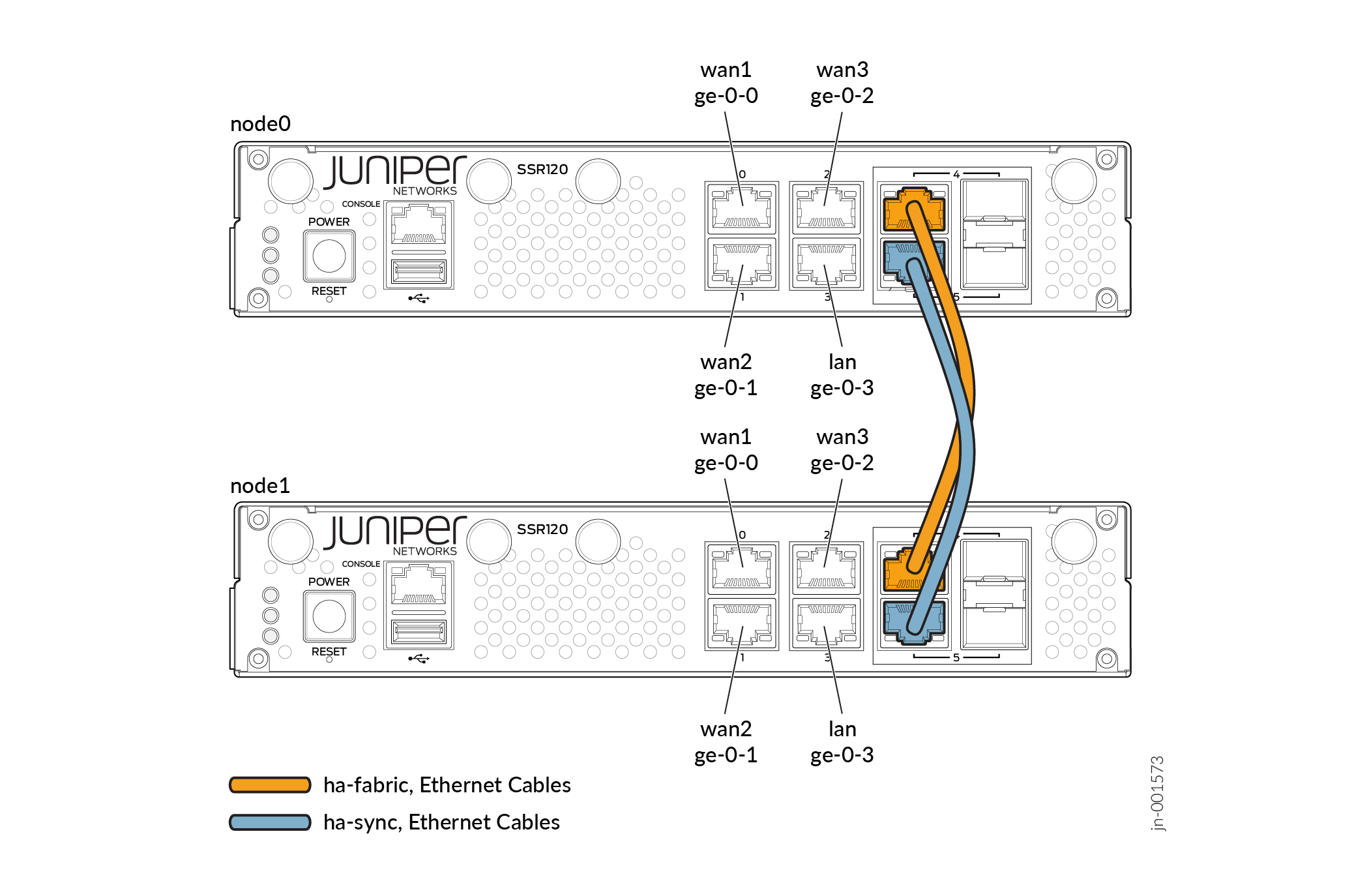
同期インターフェイスとファブリック インターフェイスは、通常、システムの最後の 2 つのポートです。これらは、同じデータセンターに配置されている 2 つのノード間の物理接続であるため、直接パッチ ケーブルで背中合わせに配線する必要があります。以下の 図2 をご覧ください。
機能するHAクラスターを持つには、HA同期とファブリックインターフェイス専用のポートを接続する必要があります。これらに使用するポートを理解するには、 SRXクラスタースロットの番号付けと論理インターフェイスの名前付け と SSRデバイスのデフォルトポートレイアウトを参照してください。
 内の冗長ノード
ノードの冗長性を設定する
これを行うには、既存のWANエッジテンプレートを編集して適切なノードインターフェイス設定で更新するか、必要なノードインターフェイス設定で 新しいテンプレートを作成する 必要があります。この手順では、HA のテンプレートを設定する方法を示します。
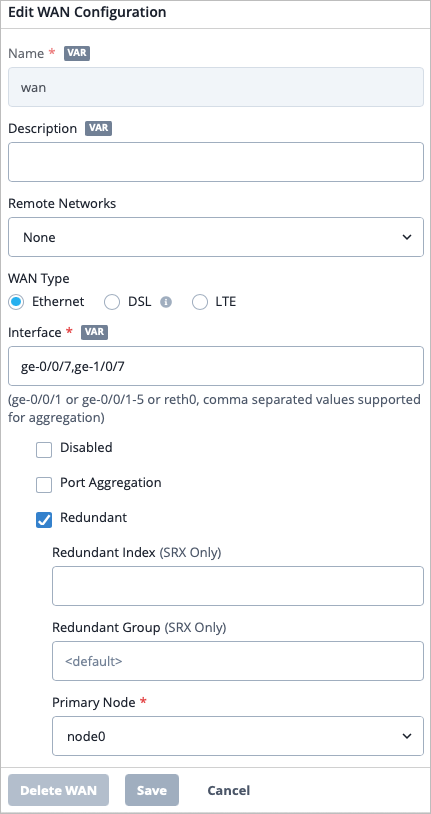
- 冗長チェックボックスを選択します。SSRにHAを設定する場合は、ステップ5に進んでください。
必要に応じて、ファブリックインターフェイスをカスタマイズします
- Mistポータルにログインします。
- 右上隅にある ? ボタンをクリックし、 API ドキュメントをクリックします。
- 目次のサイトセクションから、 HAクラスター リンクをクリックします。このドキュメントを使用して、API で HA クラスターのファブリックリンクをカスタマイズする方法を学習します。このドキュメントではSRXの使用方法を示していますが、どのタイプのWANエッジデバイスにも適用できます。
- グローバルリージョンのAPI URLに移動し、指示に従ってファブリックインターフェイスをカスタマイズします。 APIエンドポイントとグローバルリージョン を参照してください。
- APIの使用方法の詳細については、「Django Webインターフェイスを使用してAPIを変更する」、「その他のRESTful APIドキュメント」、「ジュニパー Mist APIリファレンス」を参照してください。
サイトへのテンプレートの割り当て
HAデバイスをサイトに割り当て、HAクラスターを作成する
WANエッジデバイスは、HAクラスターとして動作するように設定できます。HAクラスターでは、1組のデバイスを接続し、単一のデバイスとして動作するように設定して高可用性を実現できます。高可用性を実現するために、既存のWANエッジデバイスを新しいWANエッジデバイスでクラスター化することができます。Mistでは、WANエッジデバイスを自動的にクラスター化できます。
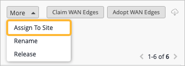
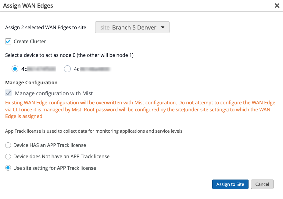
- ページの右上隅にある さらに表示 ボタンをクリックし、 サイトに割り当てを選択します。サイトを2つのデバイスに同時に割り当てることができるのは、それらのデバイスが同じハードウェアモデルである場合のみです。
- クラスターの作成チェックボックスを選択します。このチェックボックスを選択すると、[Mistで設定を管理]オプションが自動的に選択されます。
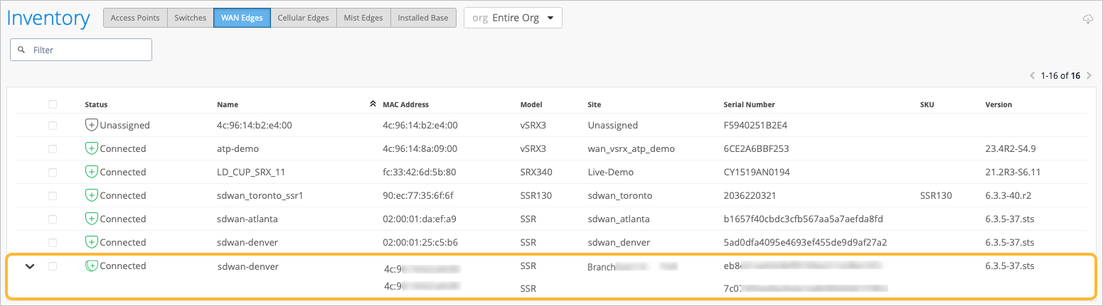
- デバイスがクラスター化されていることを確認します。インベントリリスト内のデバイスの左側にある二重のグラフィックは、デバイスが正常にクラスター化されたことを示しています。行を展開して、2つのデバイスのMACアドレスを表示することもできます。
トラフィックステアリングルールを設定する
トラフィックステアリングルールは、 ある場所またはデバイスから別の場所またはデバイスへのデータトラフィックの流れを誘導します。これらのルールは、ネットワーク内でのデータパケットのルーティング方法を制御し、効率的で最適化されたデータ配信を確保するのに役立ちます。
トラフィックステアリングの詳細については、 トラフィックステアリングルール および トラフィックステアリングを使用したハブツースポークからのパス選択の設定を参照してください。
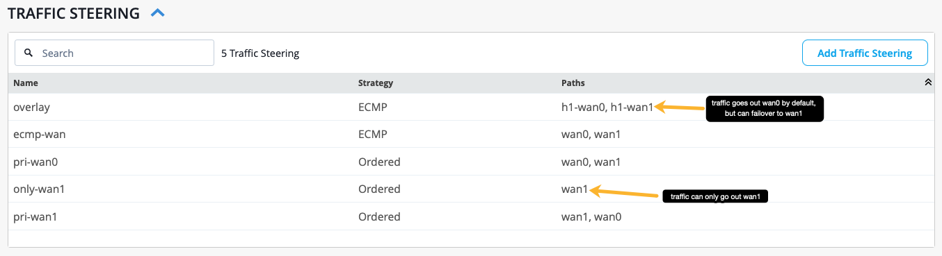
以下の表1は、1つのトラフィックステアリングルールの設定例を示しています。1つのルールに複数のパスを含めることができ、アプリケーションに到達したときにトラフィックが取るプライマリパスと、最初のパスがダウンした場合にトラフィックがたどることができるセカンダリパスを指定できます。アプリケーションポリシーを作成し、トラフィックステアリングルールを適用すると、トラフィックはアプリケーションへのアクセスを試みたときにそのルールに従います。
| 名前 | オーバーレイ |
|---|---|
| 戦略 | ECMP |
| パス | H1-WAN0、H1-WAN1 |
以下の 図3 では、複数のトラフィックステアリングルールが設定されています。トラフィックがたどるプライマリパスはリストされた最初のパスで、リストされている2番目のパスは、必要に応じてトラフィックがフェイルオーバーできるセカンダリパスです(左から右)。
アプリケーションポリシーの設定
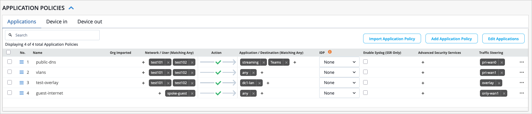
次に、WANエッジテンプレートのアプリケーションポリシーを変更して、どのネットワークとユーザーがどのアプリケーションにアクセスできるか、どのトラフィックステアリングポリシーを使用するかを定義します。新しいアプリケーションポリシーを作成する方法については、「 アプリケーションポリシー」を参照してください。
表2は 、1つのアプリケーションポリシーの設定例を示しています。
| フィールド | 設定方法 |
|---|---|
| 名前 | ゲストインターネット |
| ネットワーク | スポークゲスト |
| アクション | 許可 |
| アプリケーション/宛先 | 任意 |
| トラフィックステアリング | only-wan1 |
図4では、アプリケーションポリシーが図3のトラフィックステアリングルールで構成されています。「public-dns」アプリケーションポリシーでは、トラフィックは「pri-wan0」トラフィックステアリングルールで定義されているように、wan0をプライマリパスとして、wan1をバックアップパスとして使用します。「ゲストインターネット」アプリケーションポリシーでは、トラフィックはwan1パスのみを通ることが定められています。
高可用性クラスターの設定(ビデオチュートリアル)
In this video, we will demonstrate how SRX series devices can be configured to operate in cluster mode. Cluster mode is where a pair of devices can be connected together and configured to operate as a single device in order to provide high availability. With MIST, we are able to cluster our SRX devices and SSR devices automatically.
At this point, we are already logged into the MIST portal and we are currently looking at the WAN edges page. Two devices have already been onboarded using zero-touch provisioning. During that process, the boxes are connected to the network and are powered on.
They phone home automatically to the MIST cloud and they onboard themselves. By looking at the site column, we can see that no sites have been assigned to our SRX300s. We can assign sites to both of these devices at the same time because both devices are of the same model.
Once the devices have been selected, the More button will appear in the top right corner of the screen. We'll click the More button and then we'll click the Assign to Site option. In the Assign WAN Edges window, we'll click the dropdown to select a site to assign to the selected devices.
Note, the action of putting the device into a site is what builds the cluster. We will discuss the role that sites play in SRX clustering later in this video. Notice the Create Cluster option.
Note, the Create Cluster option will not be available if the user has selected a single device or if the selected devices are not matching models. Once the Create Cluster option has been selected, notice that the Manage Configuration with Mist option is automatically selected in grayed out. This means that when we create the cluster, it will be Mist managed.
Now we'll click on the Assign to Site button to save the changes. We can see that the two devices have been assigned a new site. Now we'll click Close to close the window.
At this point, on the SRX platform, the box needs to be rebooted from standalone mode to cluster mode. This is normally a manual process that the user would have to go through. With MIST, however, this process has been automated.
MIST will run the correct commands on each box individually to build them into a cluster. Note, this process can take up to 15 minutes to complete. At this point, the device is connected to the MIST cloud.
We can see that the device has a double graphic next to it, indicating that the two devices have been clustered. Now we'll click on the arrow to the left of the row to expand more information. The box is connected, and we can see both serial numbers listed in the Serial Number column, which is another indication that the two devices have been clustered successfully.
To see more detailed information on the clustered devices, we can click on the row. We are now brought to the WAN Edges page. At the top of the page, we see both nodes listed.
MIST will automatically assign the lower MAC address to node 0, or the primary node, and the higher MAC address to node 1, or the secondary node. We can also use the Secondary and Primary buttons at the top left of the page to see information about the individual nodes. In the top right section of the page, we can click on either of the fabric interfaces.
This will draw a line between the two interfaces, indicating their connection. Scrolling down on the page, in the Properties section, we can see that there is a template bound to the site. A full configuration was delivered to the device because of the template that is bound.
It is important to note that the action of putting the device into a site is what builds the cluster. We will click on the template now to see more information. Notice that within a template, once we click on the interface name, in this case WAN0, we have the ability to configure the elements that we want to be configured on the device.
For example, we can enter the names of the interfaces that we want to be redundant, and we can indicate that the nodes are redundant. Navigating back to the WAN Edges page, we see the WAN Edge Insights link. Clicking on this link will bring us to the Insights page, where we can gather details about what is going on with the device.
For example, we see events for ConfigChangedByUser and WAN Edge Connected. From the list of events, we can see that the configuration was delivered to the device. Therefore, we know that this is now a working node within our SD-WAN environment.
At the bottom of the page, we can see that tunnels were built and BGP was stood up for our cluster. That concludes this video on how to create an SRX cluster. I hope you enjoyed.
Have a good day.