Edge-Routed Bridging Overlay Design and Implementation
Another overlay option for this reference design is the edge-routed bridging (ERB) overlay, as shown in Figure 1.
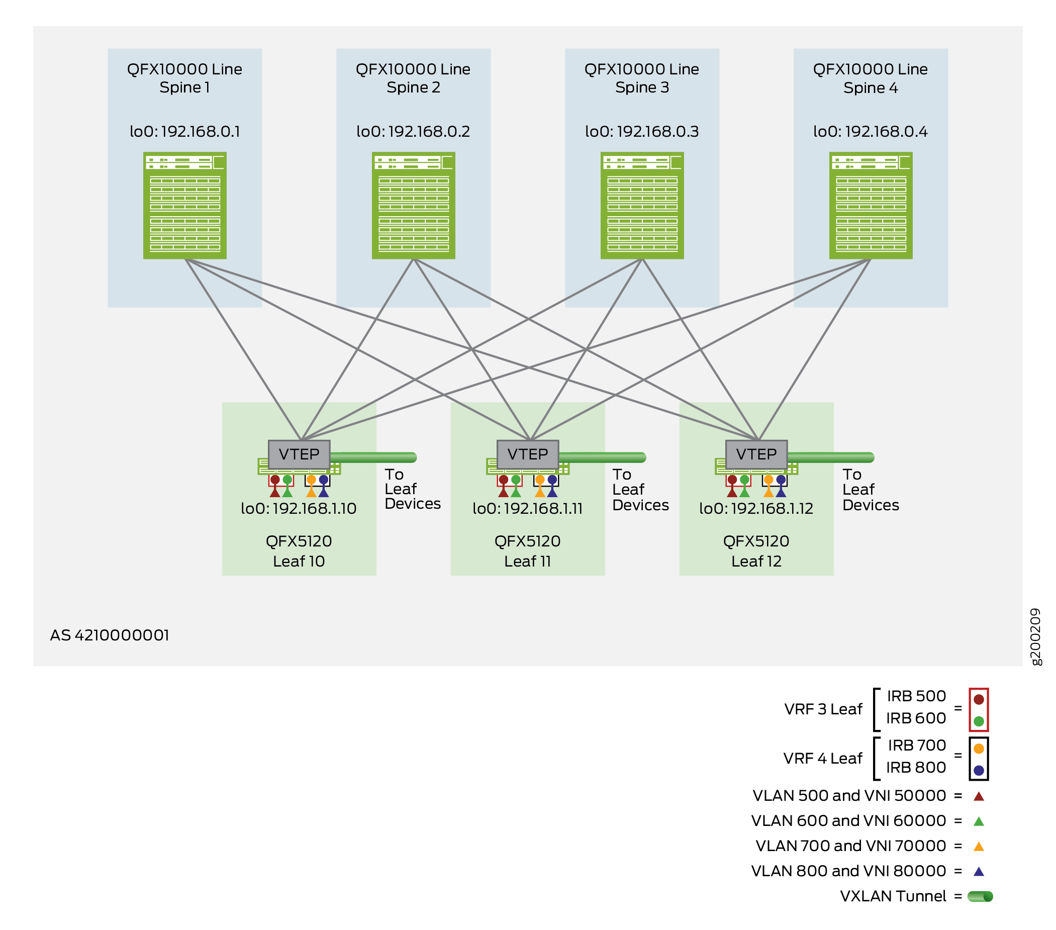
The ERB overlay performs routing at IRB interfaces located at the edge of the overlay (most often at the leaf devices). As a result, Ethernet bridging and IP routing happen as close to the end systems as possible, but still support Ethernet dependent applications at the end system level.
You can configure ERB overlay architectures using the traditional IPv4 EBGP underlay with IPv4 IBGP overlay, peering, or alternatively (with supported platforms) use an IPv6 EBGP underlay with IPv6 EBGP overlay peering. The configuration procedures in this section describe the configuration differences, where applicable, with an IPv6 Fabric instead of an IPv4 Fabric.
For a list of devices that we support as lean spine and leaf devices in an ERB overlay, see the Data Center EVPN-VXLAN Fabric Reference Designs—Supported Hardware Summary. That list includes which devices support an IPv6 Fabric when serving in different device roles.
Lean spine devices handle only IP traffic, which removes the need to extend the bridging overlay to the lean spine devices. With this limited role, on these devices you configure only the IP fabric underlay and BGP overlay peering (either an IPv4 Fabric or an IPv6 Fabric).
On the leaf devices, you can configure an ERB overlay using the default switch instance or using MAC-VRF instances.
Keep the following in mind when you configure an ERB overlay for an EVPN-VXLAN network:
-
On any Junos OS Evolved devices, we support EVPN-VXLAN configurations with MAC-VRF instances only.
-
We support the IPv6 Fabric infrastructure design with MAC-VRF instances only.
-
On the QFX5130 and QFX5700 switches in the EVPN fabric, make sure you configure the
host-profileunified forwarding profile to support an EVPN-VXLAN environment (see Layer 2 Forwarding Tables for details):set system packet-forwarding-options forwarding-profile host-profile
Some configuration steps that affect the Layer 2 configuration differ with MAC-VRF instances. Likewise, a few steps differ for IPv6 Fabric configurations. The leaf device configuration includes the following steps:
-
Configure the default instance with the loopback interface as a VTEP source interface. Or if your configuration uses MAC-VRF instances, configure a MAC-VRF instance with the loopback interface as a VTEP source interface. If your fabric uses an IPv6 Fabric, you configure the VTEP source interface as an IPv6 interface. In each MAC-VRF instance, you also configure a service type, a route distinguisher, and a route target.
-
Configure a leaf-to-end system aggregated Ethernet interface as a trunk to carry multiple VLANs. With MAC-VRF instances, you also include the interface in the MAC-VRF instance.
-
Establish LACP and ESI functionality.
-
Map VLANs to VXLAN network identifiers (VNIs). For a MAC-VRF instance configuration, you configure the VLAN to VNI mappings in the MAC-VRF instance.
-
Configure proxy-macip-advertisement, virtual gateways, and static MAC addresses on the IRB interfaces.
-
Configure EVPN/VXLAN in the default instance or in the MAC-VRF instance.
-
Enable Layer 3 (L3) tenant virtual routing and forwarding (VRF) instances and IP prefix route properties for EVPN Type 5.
-
Optionally enable symmetric IRB routing with EVPN Type 2 routes on the leaf devices. Symmetric Type 2 routing avoids scaling issue when your EVPN network has many VLANs and many attached hosts or servers. With symmetric Type 2 routing, on each leaf device you only need to configure the VLANs that leaf devices serves. We support symmetric Type 2 routing only with MAC-VRF EVPN instances.
For more information about MAC-VRF instances and using them in an example customer use case with an ERB overlay, see EVPN-VXLAN DC IP Fabric MAC-VRF L2 Services.
The following sections show the steps to configure and verify the ERB overlay:
Configure an Edge-Routed Bridging Overlay on a Lean Spine Device
To enable the ERB overlay on a lean spine device, perform the following:
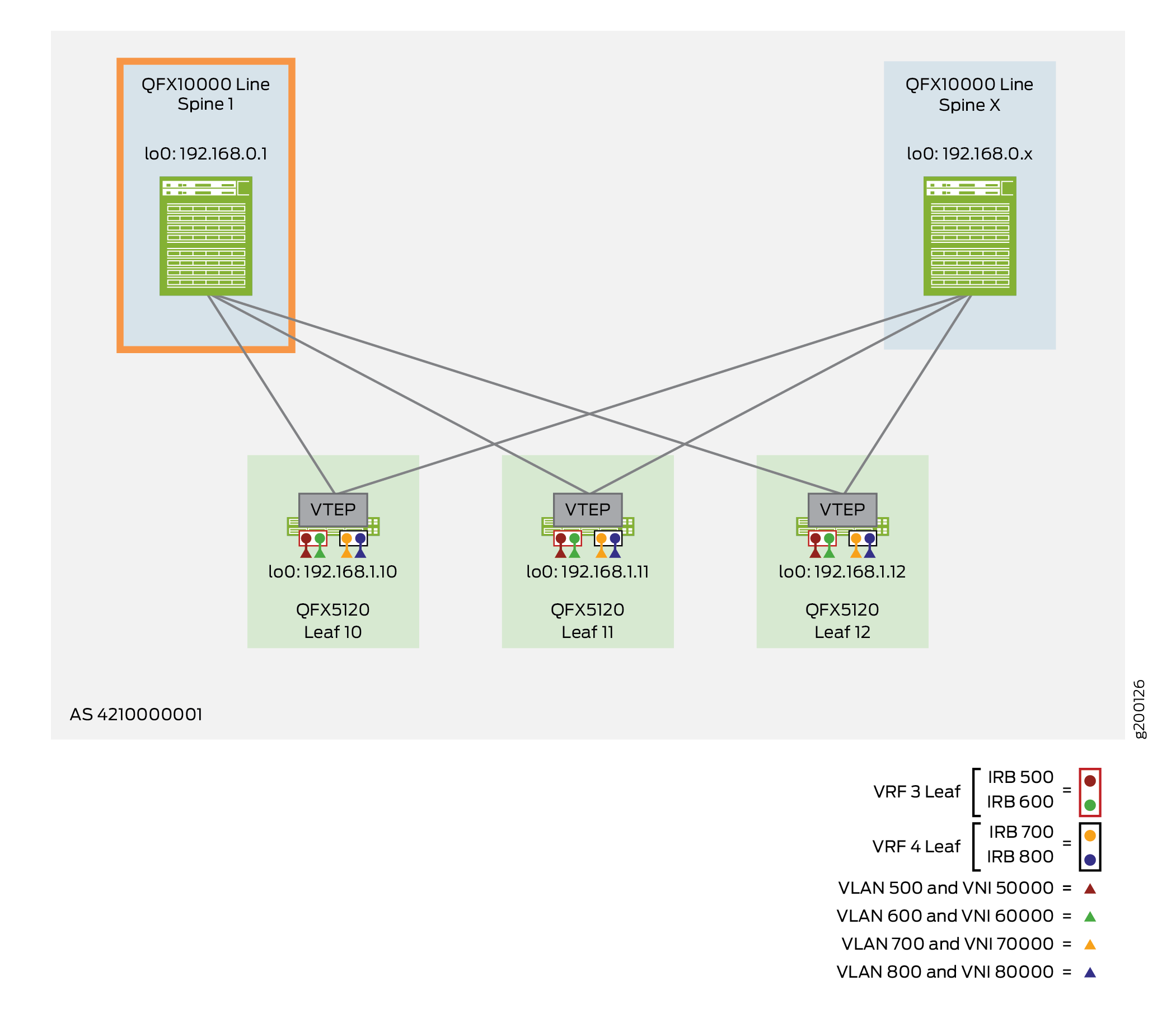
The following example shows the configuration for Spine 1, as shown in Figure 2.
Verify the Edge-Routed Bridging Overlay on a Lean Spine Device
To verify that IBGP is functional on a lean spine device, use the show bgp
summary command as described in Configure IBGP
for the Overlay. In the output that displays, ensure that the state of the lean
spine device and its peers is Establ (established).
Use the same command if you have an IPv6 Fabric. In the output, look for the IPv6
addresses of the peer device interconnecting interfaces (for underlay EBGP peering) or
peer device loopback addresses (for overlay EBGP peering). Ensure that the state is
Establ (established).
Configure an Edge-Routed Bridging Overlay on a Leaf Device
To enable the ERB overlay on a leaf device, perform the following:
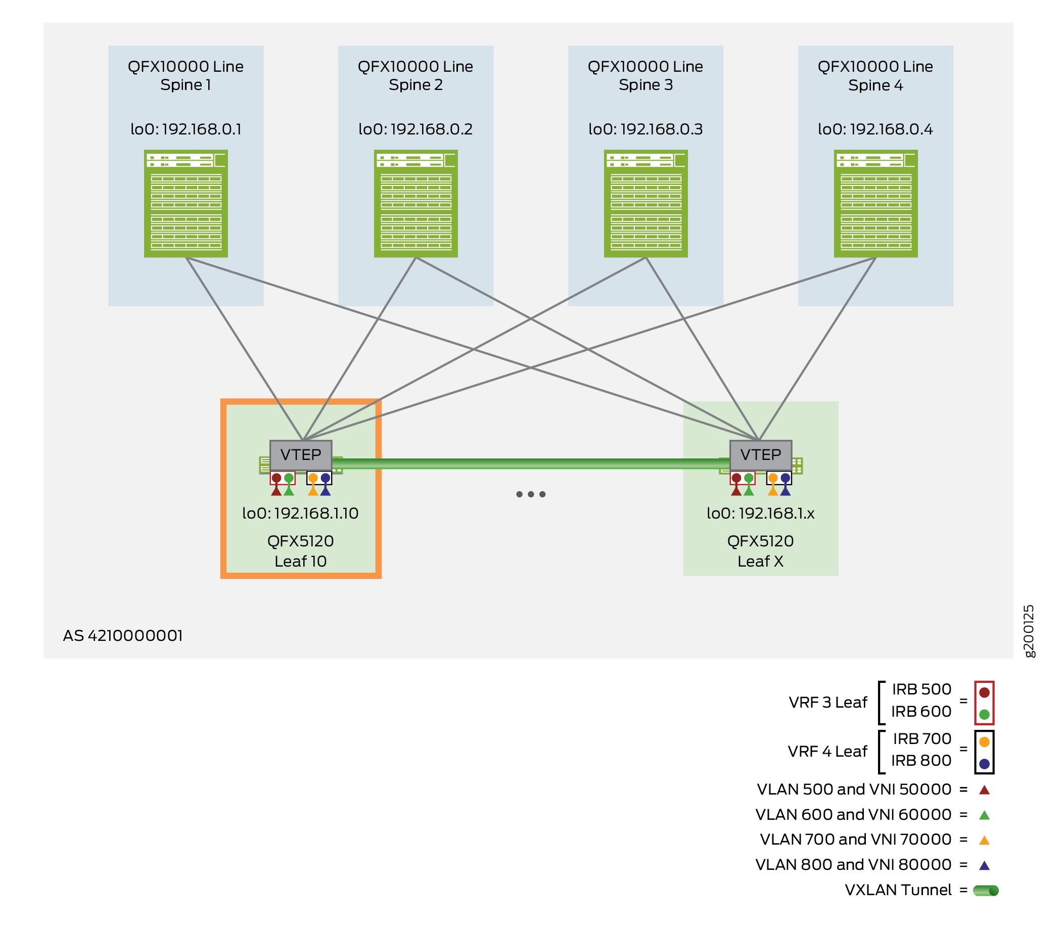
The following example shows the configuration for Leaf 10, as shown in Figure 3.
Verify the Edge-Routed Bridging Overlay on a Leaf Device
To verify that the ERB overlay is working, run the following commands.
The commands here show output for a default instance configuration. With a MAC-VRF instance configuration, you can alternatively use:
-
show mac-vrf forwardingcommands that are aliases for theshow ethernet-switchingcommands in this section. -
The
show mac-vrf routing databasecommand, which is an alias for theshow evpn databasecommand in this section.
The output with a MAC-VRF instance configuration displays similar information for MAC-VRF routing instances as this section shows for the default instance. One main difference you might see is in the output with MAC-VRF instances on devices where you enable the shared tunnels feature. With shared tunnels enabled, you see VTEP interfaces in the following format:
vtep-index.shared-tunnel-unit
where:
-
index is the index associated with the MAC-VRF routing instance.
-
shared-tunnel-unit is the unit number associated with the shared tunnel remote VTEP logical interface.
For example, if a device has a MAC-VRF instance with index 26 and the instance connects to two remote VTEPs, the shared tunnel VTEP logical interfaces might look like this:
vtep-26.32823
vtep-26.32824
If your configuration uses an IPv6 Fabric, you provide IPv6 address parameters where applicable. Output from the commands that display IP addresses reflect the IPv6 device and interface addresses from the underlying fabric. See IPv6 Fabric Underlay and Overlay Network Design and Implementation with EBGP for the fabric parameters reflected in command outputs in this section with an IPv6 Fabric.
See Also
Configure Symmetric IRB Routing with EVPN Type 2 Routes on Leaf Devices
In EVPN-VXLAN ERB overlay networks, by default, leaf devices use an asymmetric IRB model with EVPN Type 2 routes to send traffic between subnets across the VXLAN tunnels, where:
-
L3 routing for inter-subnet traffic happens at the ingress device. Then the source VTEP forwards traffic at L2 toward the destination VTEP.
-
The traffic arrives at the destination VTEP, and that VTEP forwards the traffic on the destination VLAN.
-
For this model to work, you must configure all source and destination VLANs and their corresponding VNIs on all leaf devices.
You can alternatively enable symmetric IRB routing with Type 2 routes (called symmetric Type 2 routing here for brevity). We support symmetric Type 2 routing only in ERB overlay fabrics.
To use the symmetric IRB model to route traffic for a VRF, you must enable it in that VRF on all the leaf devices in the fabric. However, you don't need to configure all VLANs and VNIs in the VRF on all leaf devices. On each leaf device, you can configure only the host VLANs that leaf device serves. As a result, using symmetric Type 2 routing helps with scaling when your EVPN network has a large number of VLANs and many attached hosts or servers. We highlight this benefit here when we show how to enable symmetric Type 2 routing in the ERB overlay reference architecture in this chapter.
With the symmetric Type 2 routing model, the VTEPs route between subnets in a tenant VRF instance using the same VNI in either direction. Symmetric Type 2 routing for a VRF shares the L3 VNI tunnel you configure for EVPN Type 5 routing in the VRF. The implementation requires you to also configure EVPN Type 5 routing in the VRF. See Symmetric Integrated Routing and Bridging with EVPN Type 2 Routes in EVPN-VXLAN Fabrics for more details on asymmetric and symmetric IRB routing models, and how symmetric Type 2 routing works.
In this section, you update the configuration for the EVPN instance MAC-VRF-1 from Configure an Edge-Routed Bridging Overlay on a Leaf Device to include four more VLANs, VNI mappings, and corresponding IRB interfaces. You include the IRB interfaces in another tenant VRF called VRF_2 as follows:
-
Leaf 10—IRB 100
-
Leaf 11—IRB 200
-
Leaf 12—IRB 300 and IRB 400
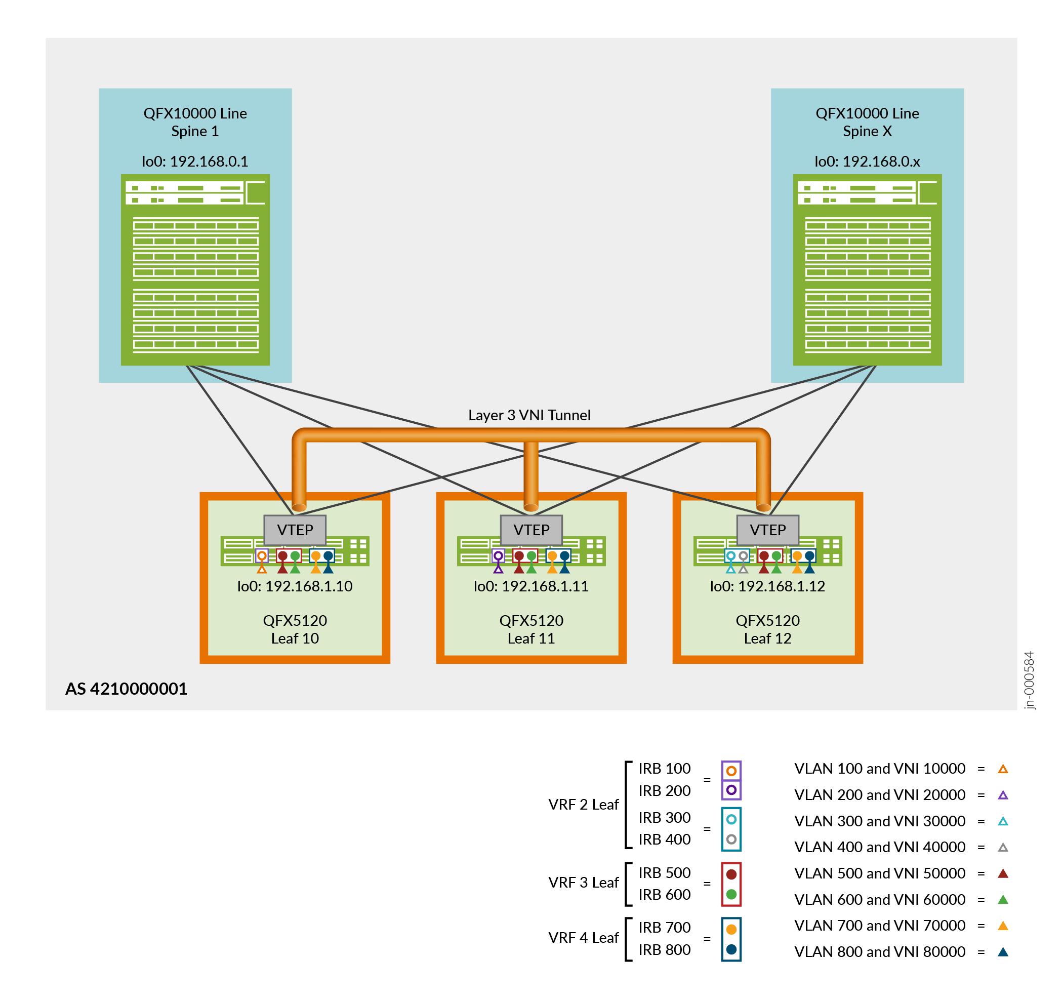
See Figure 4.
The VNI for the L3 VNI tunnel in the figure is the VNI you configure for EVPN Type 5 routing in VRF_2. We enable symmetric Type 2 routing with the same VNI in VRF_2. Again, note that with symmetric Type 2 routing, you don't need to configure all VLANs in the VRF on all leaf devices.
You must configure the EVPN instance using instance type MAC-VRF on the leaf devices in
the ERB overlay fabric according to the instructions in Configure an Edge-Routed Bridging Overlay on a Leaf Device.
Use a different route distinguisher on each leaf device—in this configuration, the route
distinguishers mirror the device lo0.0 loopback addresses on the device. This
configuration includes the same MAC-VRF instance and the same instance
vrf-target value, but these don't need to be the same on all the leaf
devices for symmetric Type 2 routing to work.
To enable symmetric Type 2 routing on the leaf devices according to Figure 4, perform these additional configuration steps as indicated in each step for Leaf 10, Leaf 11, and Leaf 12.
Verify Symmetric IRB Routing with EVPN Type 2 Routes on a Leaf Device
In Configure Symmetric IRB Routing with EVPN Type 2 Routes on Leaf Devices, you enable symmetric Type 2 routing in VRF_2 on:
-
Leaf 10 for VLAN 100 with VNI 10000, irb.100 = 10.1.0.1/24
-
Leaf 11 for VLAN 200 with VNI 20000, irb.200 = 10.1.1.1/24
-
Leaf 12 for:
-
VLAN 300 with VNI 30000, irb.300 = 10.1.2.1/24
-
VLAN 400 with VNI 40000, irb.400 = 10.1.3.1/24
-
In this section, on Leaf 10, we view routes toward Leaf 11 to verify that the leaf devices invoke symmetric Type 2 routing.