Help us improve your experience.

Let us know what you think.

Do you have time for a two-minute survey?


IPv6 Fabric Underlay and Overlay Network Design and Implementation with EBGP

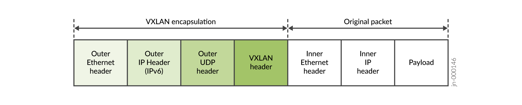
Most use cases in this guide are based on an IP Fabric that uses IPv4 and EBGP for underlay connectivity with IBGP overlay peering. On supporting platforms, starting in Junos OS Release 21.2R2-S1 and 21.4R1, you can alternatively use an IPv6 Fabric infrastructure. With an IPv6 Fabric, the VXLAN virtual tunnel endpoints (VTEPs) encapsulate the VXLAN header with an IPv6 outer header and tunnel the packets using IPv6. The workload packets with the payload can use either IPv4 or IPv6. See Figure 1.

Figure 1: IPv6 Fabric VXLAN Packet EncapsulationIPv6 Fabric VXLAN Packet Encapsulation

An IPv6 Fabric uses IPv6 addressing, IPv6 and EBGP for underlay connectivity, and IPv6 and EBGP for overlay peering. You can’t mix IPv4 and IPv6 underlays and overlay peering in the same fabric.

This section describes how to configure the IPv6 Fabric design. In this environment, you can take advantage of the expanded addressing capabilities and efficient packet processing that the IPv6 protocol offers.

We have qualified this IPv6 Fabric in our reference architectures with:

  • The following routing and bridging overlay designs:

    • Bridged overlay

    • Edge-routed bridging (ERB) overlay

  • EVPN instances configured using MAC-VRF routing instances only.

Figure 2 shows a high-level representative view of the spine and leaf devices in an IPv6 Fabric.

Figure 2: Basic Spine and Leaf Fabric with an IPv6 FabricBasic Spine and Leaf Fabric with an IPv6 Fabric

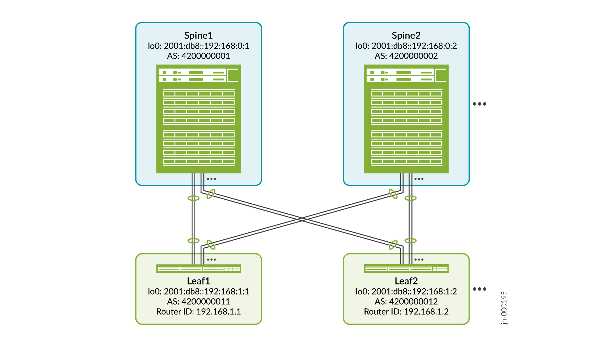
The topology can be the same or similar to the supported topologies with an IPv4 Fabric.

The main differences in how you configure an IPv6 Fabric instead of an IPv4 Fabric include:

  • You configure IPv6 interfaces to interconnect the devices.

  • You assign an IPv6 address to the loopback interface on the devices serving as VTEPs.

  • In the EVPN routing instance, you set the VTEP source interface as the device’s loopback IPv6 address, rather than an IPv4 address.

  • You configure the underlay EBGP peering between the IPv6 interface addresses interconnecting the devices. You configure the overlay EBGP peering between the device IPv6 loopback addresses.

See Data Center EVPN-VXLAN Fabric Reference Designs—Supported Hardware Summary for the initial hardened release in which a platform supports an IPv6 fabric design, based on the type of overlay architecture and the role the device serves in the fabric. Look for the table rows that state the device role “with IPv6 underlay”.

See EVPN-VXLAN with an IPv6 Underlay in the EVPN User Guide for an overview of EVPN-VXLAN feature support and limitations with an IPv6 Fabric.

For an overview of the supported IP fabric underlay and overlay models and components used in our reference architecture designs, see Data Center Fabric Blueprint Architecture Components.

Configure Interfaces and EBGP as the Routing Protocol in the IPv6 Fabric Underlay

In this design (similar to the IPv4 Fabric in IP Fabric Underlay Network Design and Implementation), you interconnect the spine and leaf devices using aggregated Ethernet interfaces with two member links. (You can alternatively use a single link, or more than two member links in an aggregated Ethernet bundle, for each spine and leaf connection.)

This procedure shows how to configure the interfaces on the leaf side toward the spines, and enable EBGP with IPv6 as the underlay routing protocol on the leaf device.

Note:

Although this procedure doesn’t show the spine side configuration, you configure the interconnecting interfaces and the EBGP underlay on the spine side in the same way as you do on the leaf device.

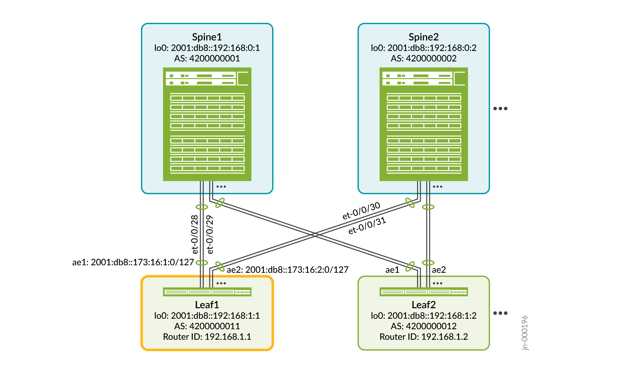
Figure 3 shows the interfaces on leaf device Leaf1 that you configure in this procedure.

Figure 3: Leaf1 Interfaces and IPv6 Addressing with EBGP for Spine and Leaf ConnectivityLeaf1 Interfaces and IPv6 Addressing with EBGP for Spine and Leaf Connectivity

To configure aggregated Ethernet interfaces and EBGP in the underlay with IPv6 on Leaf1:

  1. Set the maximum number of aggregated Ethernet interfaces permitted on the device.

    We recommend setting this number to the exact number of aggregated Ethernet interfaces on your device, including aggregated Ethernet interfaces that are not for the spine to leaf device connections here. In this scaled-down example, we set the count to 10. If you have more spine and leaf devices or employ aggregated Ethernet interfaces for other purposes, set the appropriate number for your network.

  2. Create the aggregated Ethernet interfaces toward the spine devices, optionally assigning a description to each interface.
  3. Assign interfaces to each aggregated Ethernet interface.

    In this case, we show creating aggregated Ethernet interfaces with two member links each. In this step, you also specify the minimum number of links (one) that have to remain up before all links in the aggregated Ethernet interface stop sending and receiving traffic.

  4. Assign an IPv6 address to each aggregated Ethernet interface.

    In this step, you also specify the interface MTU size. You set two MTU values for each aggregated Ethernet interface, one for the physical interface and one for the IPv6 logical interface. We configure a higher MTU on the physical interface to account for VXLAN encapsulation.

  5. Enable fast LACP on the aggregated Ethernet interfaces.

    You enable LACP with the fast periodic interval, which configures LACP to send a packet every second.

  6. Configure an IPv6 loopback address and a router ID on the device.

    Although the underlay uses the IPv6 address family, for BGP handshaking to work in the overlay, you must configure the router ID as an IPv4 address.

    The router ID is often the device’s IPv4 loopback address, but is not required to match that address. For simplicity in this example, we don’t assign an IPv4 loopback address, but to easily associate device IPv6 addresses and router IDs, we assign IPv4 router IDs with similar address components. In Figure 3, the device IPv6 loopback address for Leaf1 is 2001:db8::192:168:1:1 and the IPv4 router ID is 192.168.1.1.

  7. Enable EBGP (type external) with IPv6 as the underlay network routing protocol.

    With EBGP, each device in the underlay fabric has a unique local 32-bit autonomous system (AS) number (ASN). Figure 3 shows the ASN values for each device in this configuration example. The EBGP ASN for Leaf1 is 4200000011. Leaf1 connects to Spine1 (ASN 4200000001) and Spine2 (ASN 4200000002) using the IPv6 addresses of the aggregated Ethernet interfaces toward each spine device. The underlay routing configuration ensures that the devices can reliably reach each other.

    The only difference in this configuration from the IPv4 Fabric configuration in IP Fabric Underlay Network Design and Implementation is that you use IPv6 addressing instead of IPv4 addressing.

    In this step, you also enable BGP multipath with the multiple AS option. By default, EBGP selects one best path for each prefix and installs that route in the forwarding table. When you enable BGP multipath, the device installs all equal-cost paths to a given destination into the forwarding table. The multiple-as option enables load balancing between EBGP neighbors in different autonomous systems.

  8. Configure an export routing policy that advertises the IPv6 address of the loopback interface to the EBGP peer devices in the underlay.

    In this example, because we configure only an IPv6 address on the loopback interface, this simple policy correctly retrieves and advertises that address in the EBGP underlay.

  9. (QFX Series Broadcom-based switches running Junos OS releases in the 21.2 release train only) Enable the Broadcom VXLAN flexible flow feature on the device if needed.

    QFX Series Broadcom-based switches require the flexible flow feature to support IPv6 VXLAN tunneling. You don't need this step starting in Junos OS Release 21.4R1, where the default configuration enables this option for you on platforms that require this feature. When you set this option and commit the configuration, you must then reboot the device for the change to take effect.

Configure EBGP for IPv6 Overlay Peering

Use this procedure with an IPv6 Fabric EBGP underlay to configure the IPv6 overlay peering. Both the underlay and overlay must use IPv6, so you can’t use the overlay configuration in Configure IBGP for the Overlay (which describes configuring overlay peering in an IPv4 Fabric).

Because the overlay peering in the IPv6 Fabric also uses EBGP as the routing protocol, the overlay peering configuration is very similar to the underlay configuration in Configure Interfaces and EBGP as the Routing Protocol in the IPv6 Fabric Underlay. The main difference is that in the underlay, we specify the IPv6 addresses of the Layer 3 interfaces that connect to the EBGP neighbors (in this example, the aggregated Ethernet interface addresses). In contrast, in the overlay, we use the device IPv6 loopback addresses to specify the EBGP neighbors. Refer again to Figure 3 for the device addresses and ASN values in this example.

Another difference in the overlay configuration here is that we configure EVPN signaling.

To configure EBGP overlay peering with IPv6 on Leaf1 to Spine1 and Spine2:

  1. Enable IPv6 EBGP peering with EVPN signalling between the leaf and spine devices. Specify the device’s IPv6 loopback address as the local-address in the overlay BGP group configuration.

    In this step, similar to the underlay EBGP configuration, you also:

    • Specify the device’s local ASN.

    • Enable BGP multipath with the multiple AS option to install all equal-cost paths to a destination into the forwarding table, and enable load balancing between EBGP neighbors with different ASNs.

    In the overlay BGP group, when you configure the neighbor devices, you specify the IPv6 loopback addresses of the peer neighbor devices. (The underlay BGP group configuration uses the interconnecting aggregated Ethernet interface IPv6 address for neighbor peering.)

  2. Set the multihop option to enable EBGP peering in the overlay using device loopback addresses.

    When we use EBGP in the overlay, the EBGP peering happens between the device IPv6 loopback addresses. However, EBGP was designed to establish peering between directly-connected IP or IPv6 interface addresses. As a result, EBGP peering between device loopback addresses requires an extra hop for an EBGP control packet to reach its destination. The multihop option enables the device to establish the EBGP sessions in the overlay under these conditions.

    Also include the no-nexthop-change option with the multihop statement so that intermediate EBGP overlay peers don’t change the BGP next-hop attribute from the originating value across multiple hops.

  3. (Recommended in the overlay) Enable Bidirectional Forwarding Detection (BFD) in the overlay to help detect BGP neighbor failures.

Verify EBGP IPv6 Underlay and Overlay Device Connectivity

After you’ve committed the underlay and overlay configurations in Configure Interfaces and EBGP as the Routing Protocol in the IPv6 Fabric Underlay and Configure EBGP for IPv6 Overlay Peering, issue the following commands:

  1. Enter the show bgp summary command on Leaf1 to confirm EBGP connectivity toward the spine devices.

    The example output shows the following:

    • The established underlay connectivity with Spine1 and Spine 2—refer to the Peer column showing aggregated Ethernet interface addresses 2001:db8::173:16:1:1 and 2001:db8::173:16:2:1, respectively.

    • The established overlay peering toward Spine1 and Spine2—refer to the Peer column showing device loopback addresses 2001:db8::192:168:0:1 and 2001:db8::192:168:0:2, respectively.

  2. Enter the show bfd session command on Leaf1 to verify the BFD session is up between Leaf1 and the two spine devices (loopback IPv6 addresses 2001:db8::192:168:0:1 and 2001:db8::192:168:0:2).