IP Fabric Underlay Network Design and Implementation
For an overview of the supported IP fabric underlay models and components used in these designs, see the IP Fabric Underlay Network section in Data Center Fabric Blueprint Architecture Components.
This section explains how to configure spine and leaf devices in 3-stage and 5-stage IPv4 fabric underlays. For information about how to configure the additional tier of super spine devices in a 5-stage IP fabric underlay, see Five-Stage IP Fabric Design and Implementation. For the steps to configure an IPv6 Fabric design in reference architectures that support that configuration, see IPv6 Fabric Underlay and Overlay Network Design and Implementation with EBGP instead.
The IP underlay network building block is arranged in a Clos-based fabric topology. The underlay network uses EBGP as the routing protocol in place of a traditional IGP like OSPF. You can use other routing protocols in the underlay protocol in your data center; the usage of those routing protocols is beyond the scope of this document.
Aggregated Ethernet interfaces with MicroBFD are also used in this building block. MicroBFD improves fault detection in an aggregated Ethernet interface by running BFD on individual links of the aggregated Ethernet interface.
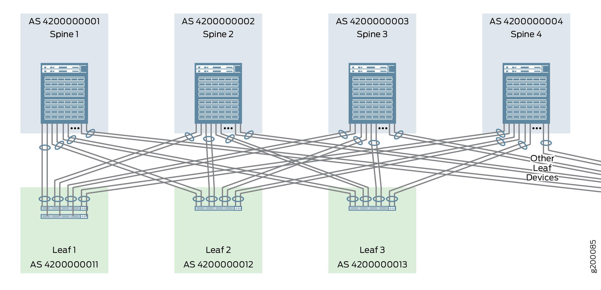
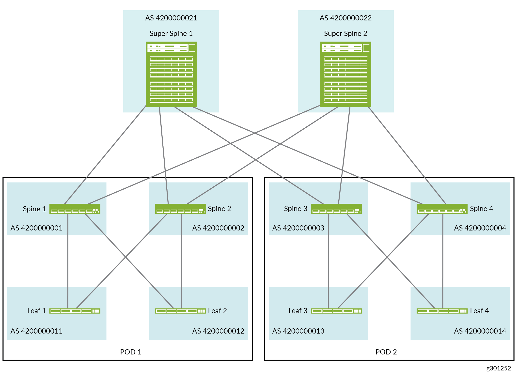
Figure 1 and Figure 2 provide high-level illustrations of a 3-stage and 5-stage IP fabric underlay networks, respectively.
Configuring the Aggregated Ethernet Interfaces Connecting Spine Devices to Leaf Devices
In this design each spine device is interconnected to each leaf device using a single link or a two-member aggregated Ethernet interface. The decision to use a single link or an aggregated Ethernet interface largely depends on the needs of your network; see Data Center Fabric Reference Design Overview and Validated Topology for more information on interface requirements.
The majority of IP Fabric topologies do not use aggregated Ethernet interfaces to interconnect spine and leaf devices. You can skip this section if you are connecting your spine and leaf devices using single links.
Use the following instructions to configure the interfaces that interconnect spine and leaf devices as aggregated Ethernet interfaces with two member links. An IPv4 address is assigned to each aggregated Ethernet interface. LACP with a fast periodic interval is also enabled.
Figure 3 shows the spine device interfaces that are configured in this procedure:
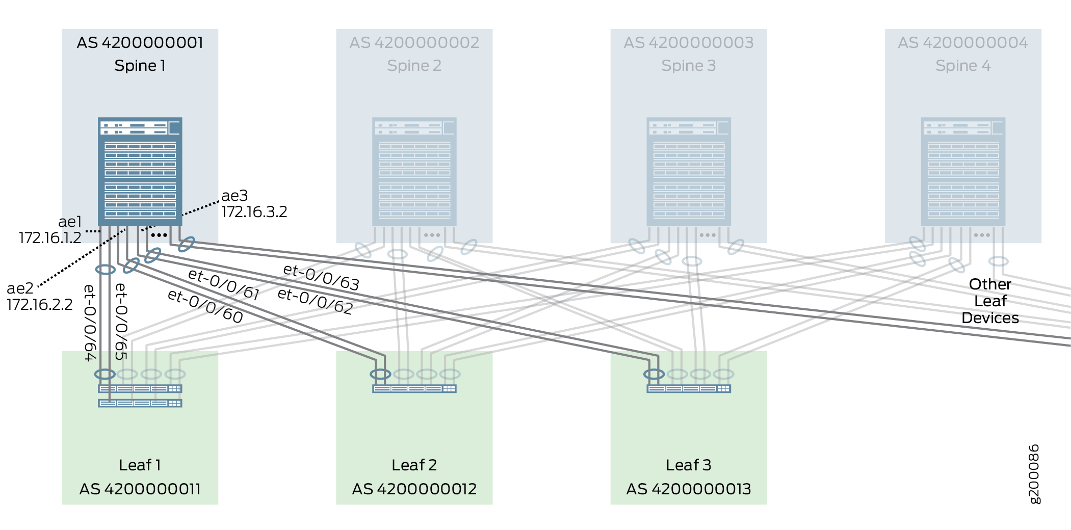
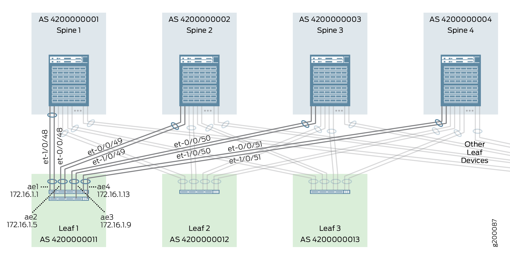
Figure 4 shows the leaf device interfaces that are configured in this procedure:
To configure aggregated Ethernet interfaces with fast LACP:
Configuring an IP Address for an Individual Link
This section covers the procedure to add an IP address to a single link interface connecting a spine or leaf device. The process for adding an IP address to an aggregated Ethernet interface is covered in Configuring the Aggregated Ethernet Interfaces Connecting Spine Devices to Leaf Devices.
To add an IP address to a single link interface:
Enabling EBGP as the Routing Protocol in the Underlay Network
In this design, EBGP is the routing protocol of the underlay network and each device in the IP fabric is assigned a unique 32-bit autonomous system number (ASN). The underlay routing configuration ensures that all devices in the underlay IP fabric are reliably reachable from one another. Reachability between VTEP across the underlay IP Fabric is also required to support overlay networking with VXLAN.
Figure 5 shows the EBGP configuration of the underlay network.
To enable EBGP as the routing protocol for the underlay network on a device:
Enabling Load Balancing
ECMP load balancing allows traffic to be sent to the same destination over multiple equal cost paths. Load balancing must be enabled on all spine and leaf devices to ensure that traffic is sent over all available paths provided by the IP Fabric.
Traffic is load balanced per Layer 4 flow on Junos devices. The ECMP algorithm load balances each traffic flow over one of the multiple paths, and all traffic for that flow is transmitted using the selected link.
To enable ECMP-based load balancing on a device:
Configuring Micro Bidirectional Forwarding Detection on Member Links in Aggregated Ethernet Interfaces
BFD is a simple bidirectional fault detection protocol that verifies bidirectional connectivity between directly-connected devices by periodically and rapidly sending a simple hello packet over the link or links that interconnect the devices. BFD can detect and communicate link faults in sub-second time frames to allow the control-plane software to quickly switch to an alternate path.
MicroBFD allows BFD to run on individual member links in an aggregated Ethernet interface.
In this design, microBFD is supported on connections between QFX10002-36Q/72Q, QFX10008, and QFX10016 switches.
To enable microBFD:
IP Fabric Underlay Network — Release History
Table 1 provides a history of all of the features in this section and their support within this reference design.
Release |
Description |
|---|---|
19.1R2 |
QFX10002-60C and QFX5120-32C switches running Junos OS Release 19.1R2 and later releases in the same release train also support all features documented in this section except the following:
|
18.4R2 |
QFX5120-48Y switches running Junos OS Release 18.4R2 and later releases in the same release train support all features documented in this section except MicroBFD. |
18.1R3-S3 |
QFX5110 switches running Junos OS Release 18.1R3-S3 and later releases in the same release train support all features documented in this section except MicroBFD. |
17.3R3-S1 |
All devices in the reference design that support Junos OS Release 17.3R3-S1 and later releases in the same release train also support all features documented in this section. The following is an exception:
|