ON THIS PAGE
How to Integrate the Super Spine Devices into the IP Fabric Underlay Network
How to Integrate the Super Spine Devices into the EVPN Overlay Network
How to Verify That the Super Spine Devices Are Integrated Into the Underlay and Overlay Networks
How to Enable the Advertisement of EVPN Type-5 Routes on the Routing Devices in the PODs
How to Verify the Advertisement of EVPN Type-5 Routes on the Routing Devices in the PODs
Five-Stage IP Fabric Design and Implementation
To enable you to scale your existing EVPN-VXLAN network in a data center, Juniper Networks supports a 5-stage IP fabric. Although a 5-stage IP fabric is actually comprised of 3 tiers of networking devices, the term 5-stage refers to the number of network devices that traffic sent from one host to another must traverse to reach its destination.
Juniper Networks supports a 5-stage IP fabric in an inter-point of delivery (POD) connectivity use case within a data center. This use case assumes that your EVPN-VXLAN network already includes tiers of spine and leaf devices in two PODs. To enable connectivity between the two PODs, you add a tier of super spine devices. To determine which Juniper Networks devices you can use as a super spine device, see the Data Center EVPN-VXLAN Fabric Reference Designs—Supported Hardware Summary table.
Figure 1 shows the 5-stage IP fabric that we use in this reference design.
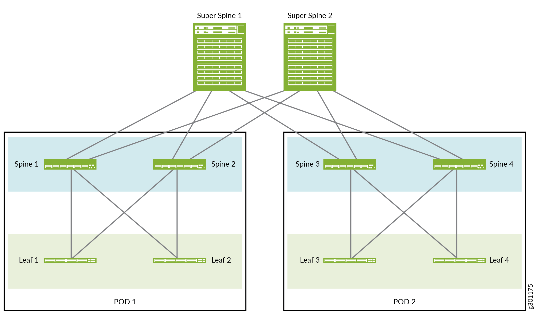
As shown in Figure 1, each super spine device is connected to each spine device in each POD.
We support the following network overlay type combinations in each POD:
The EVPN-VXLAN fabric in both PODs has a centrally routed bridging (CRB) overlay.
The EVPN-VXLAN fabric in both PODs has an edge-routed bridging (ERB) overlay.
The EVPN-VXLAN fabric in one POD has a CRB overlay, and the fabric in the other POD has an ERB overlay.
Juniper Network’s 5-stage IP fabric supports RFC 7938, Use of BGP for Routing in Large-Scale Data Centers. However, where appropriate, we use terminology that more effectively describes our use case.
Note the following about the 5-stage IP fabric reference design:
This reference design assumes that the tiers of spine and leaf devices in the two PODs already exist and are up and running. As a result, except when describing how to configure the advertisement of EVPN Type 5 routes, this topic provides the configuration for the super spine devices only. For information about configuring the spine and leaf devices in the two PODs, see the following:
The reference design integrates Super Spines 1 and 2 into existing IP fabric underlay and EVPN overlay networks.
The super spine devices have the following functions:
They act as IP transit devices only.
They serve as route reflectors for Spines 1 through 4.
When configuring the routing protocol in the EVPN overlay network, you can use either IBGP or EBGP. Typically, you use IBGP if your data center uses the same autonomous system (AS) number throughout and EBGP if your data center uses different AS numbers throughout. This reference design uses the IBGP configuration option. For information about the EBGP configuration option, see Over-the-Top Data Center Interconnect in an EVPN Network.
After you integrate Super Spines 1 and 2 into existing IP fabric underlay and EVPN overlay networks and verify the configuration, the super spine devices will handle the communication between PODs 1 and 2 by advertising EVPN type-2 routes. This method will work if your PODs use the same IP address subnet scheme. However, if servers connected to the leaf devices in each POD are in different subnets, you must configure the devices that handle inter-subnet routing in the PODs to advertise EVPN Type 5 routes. For more information, see How to Enable the Advertisement of EVPN Type-5 Routes on the Routing Devices in the PODs later in this topic.
How to Integrate the Super Spine Devices into the IP Fabric Underlay Network
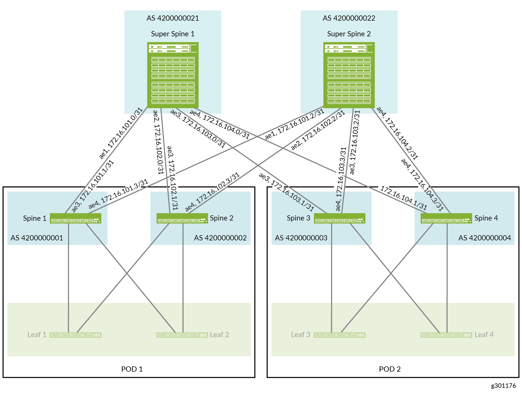
This section shows you how to configure the super spine devices so that they can communicate with the spine devices, which are already configured as part of an existing IP fabric underlay network.
For details about the interfaces and autonomous systems (ASs) in the IP fabric underlay network, see Figure 2.
How to Integrate the Super Spine Devices into the EVPN Overlay Network
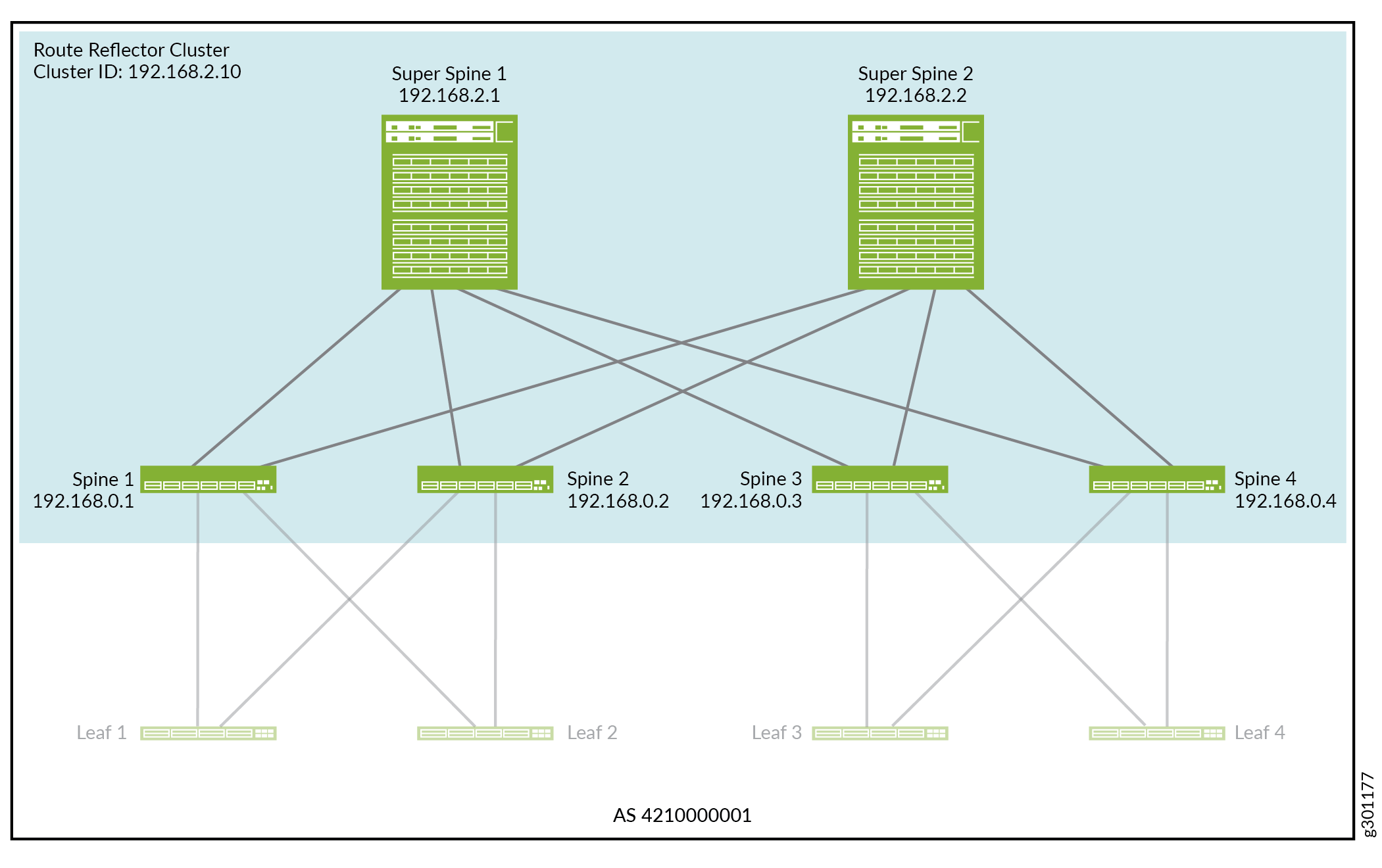
This section explains how to integrate the super spine devices into the EVPN overlay network. In this control-plane driven overlay, we establish a signalling path between all devices within a single AS using IBGP with Multiprotocol BGP (MP-IBGP).
In this IBGP overlay, the super spine devices act as a route reflector cluster, and the spine devices are route reflector clients. For details about the route reflector cluster ID and BGP neighbor IP addresses in the EVPN overlay network, see Figure 3.
How to Verify That the Super Spine Devices Are Integrated Into the Underlay and Overlay Networks
This section explains how you can verify that the super spine devices are properly integrated into the IP fabric underlay and EVPN overlay networks.
After you successfully complete this verification, the super spine devices will handle communication between PODs 1 and 2 by advertising EVPN type-2 routes. This method will work if your PODs use the same IP address subnet scheme. However, if each POD uses a different IP address subnet scheme, you must additionally configure the devices that handle inter-subnet routing in the PODs to advertise EVPN Type 5 routes. For more information, see How to Enable the Advertisement of EVPN Type-5 Routes on the Routing Devices in the PODs later in this topic.
How to Enable the Advertisement of EVPN Type-5 Routes on the Routing Devices in the PODs
After you complete the tasks in the following sections, the super spine devices will handle communication between PODs 1 and 2 by advertising EVPN type-2 routes.
How to Integrate the Super Spine Devices into the IP Fabric Underlay Network
How to Integrate the Super Spine Devices into the EVPN Overlay Network
How to Verify the Integration of the Super Spine Devices Into the Underlay and Overlay Networks
If servers connected to the leaf devices in both PODs are in the same subnet, you can skip the task in this section. However, if servers in each POD are in different subnets, you must further configure the devices that handle inter-subnet routing in the PODs to advertise EVPN Type 5 routes as described in this section. This type of route is also known as an IP prefix route.
In this EVPN Type 5 reference design, the EVPN-VXLAN fabric in both PODs has a CRB overlay. In this type of overlay, the spine devices handle inter-subnet routing. Therefore, this section explains how to enable the advertisement of EVPN Type 5 routes on the spine devices in PODs 1 and 2.
To enable the advertisement of EVPN Type 5 routes, you set up a tenant routing instance named VRF-1 on each spine device. In the routing instance, you specify which host IP addresses and prefixes that you want a spine device to advertise as EVPN Type 5 routes with a VXLAN network identifier (VNI) of 500001. A spine device will advertise the EVPN Type 5 routes to the other spine and leaf devices within the same POD. The spine device will also advertise the EVPN Type 5 routes to the super spine devices, which will in turn advertise the routes to the spine devices in the other POD. All spine devices on which you have configured VRF-1 will import the EVPN Type 5 routes into their VRF-1 routing table.
After you enable the advertisement of EVPN Type 5 routes, the super spine devices will handle communication between PODs 1 and 2 by advertising EVPN Type 5 routes.
Figure 4 shows the EVPN Type 5 configuration details for the inter-POD use case.
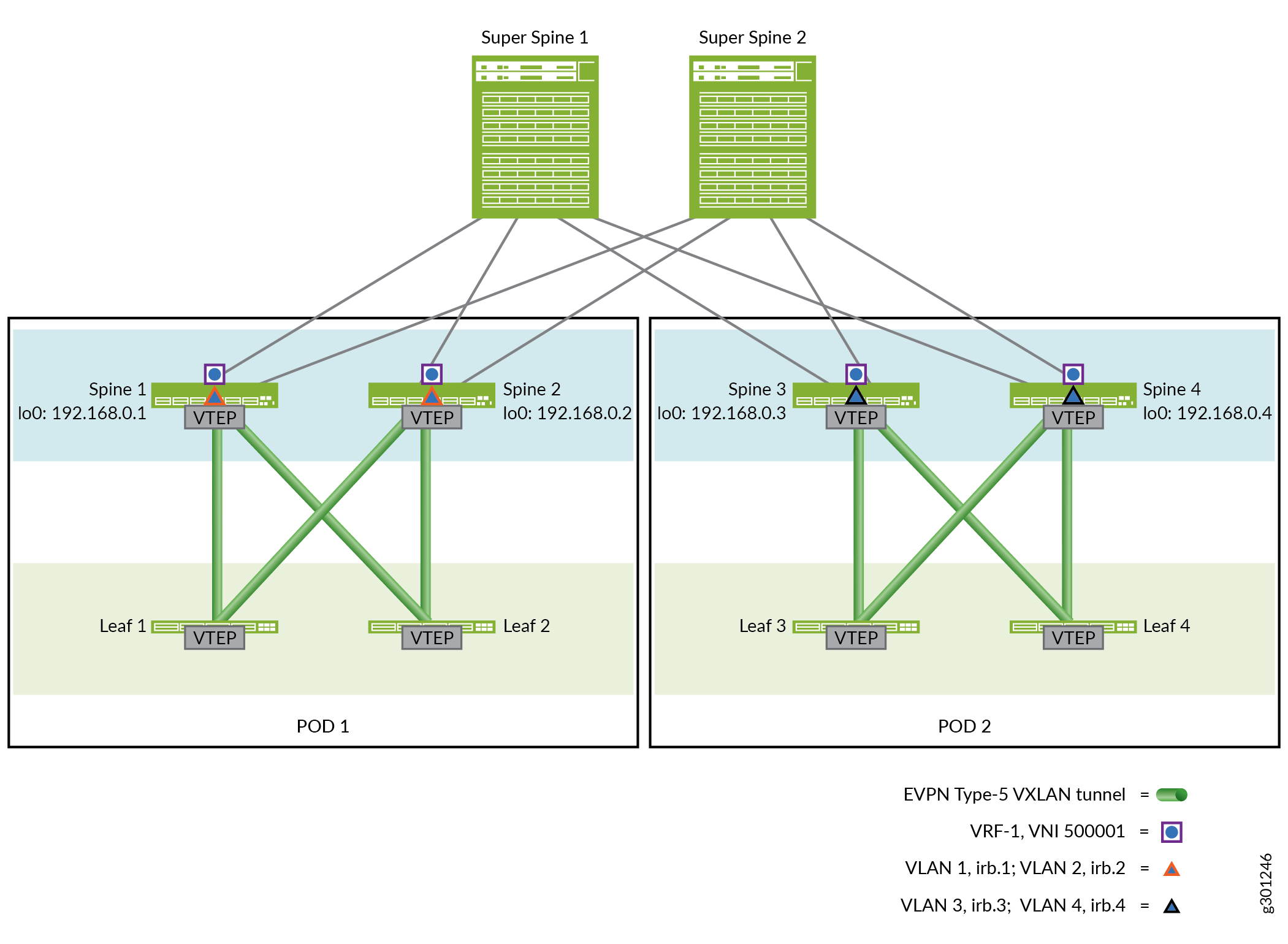
Table 1 outlines the VLAN ID to IRB interface mappings for this reference design.
VLAN Names |
VLAN IDs |
IRB Interface |
|---|---|---|
Spines 1 and 2 in POD 1 |
||
VLAN BD-1 |
1 |
irb.1 |
VLAN BD-2 |
2 |
irb.2 |
Spines 3 and 4 in POD 2 |
||
VLAN BD-3 |
3 |
irb.3 |
VLAN BD-4 |
4 |
irb.4 |
To set up the advertisement of EVPN Type 5 routes:
How to Verify the Advertisement of EVPN Type-5 Routes on the Routing Devices in the PODs
To verify that the spine devices in this reference design are properly advertising EVPN Type 5 routes: