Centrally-Routed Bridging Overlay Design and Implementation
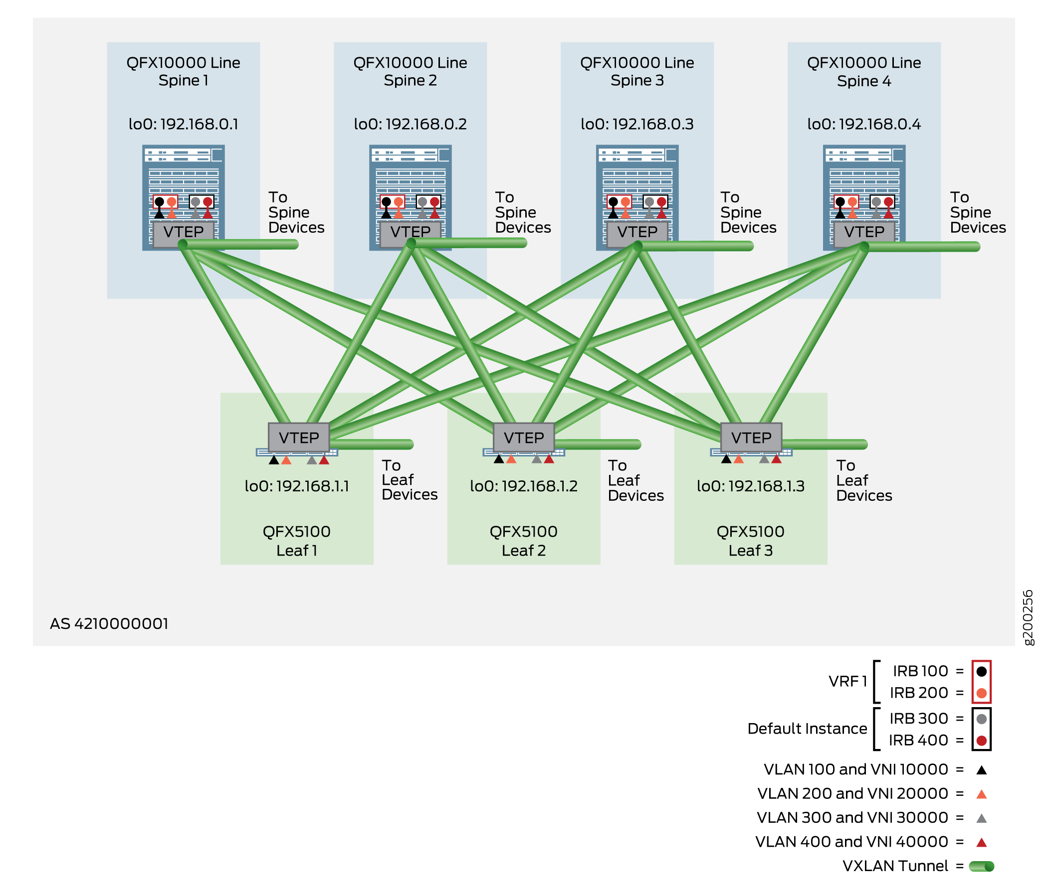
A centrally-routed bridging (CRB) overlay performs routing at a central location in the EVPN network as shown in Figure 1, In this example, IRB interfaces are configured in the overlay at each spine device to route traffic between the VLANs that originate at the leaf devices and end systems. For an overview of CRB overlays, see the Centrally-Routed Bridging Overlay section in Data Center Fabric Blueprint Architecture Components.
The following sections provide the detailed steps of how to implement a CRB overlay:
Configuring a VLAN-Aware CRB Overlay in the Default Instance
The VLAN-aware CRB overlay is a basic overlay supported on all platforms included in this reference design. It uses the simplest VLAN-aware method to enable a single, default switching instance that supports up to 4094 VLANs.
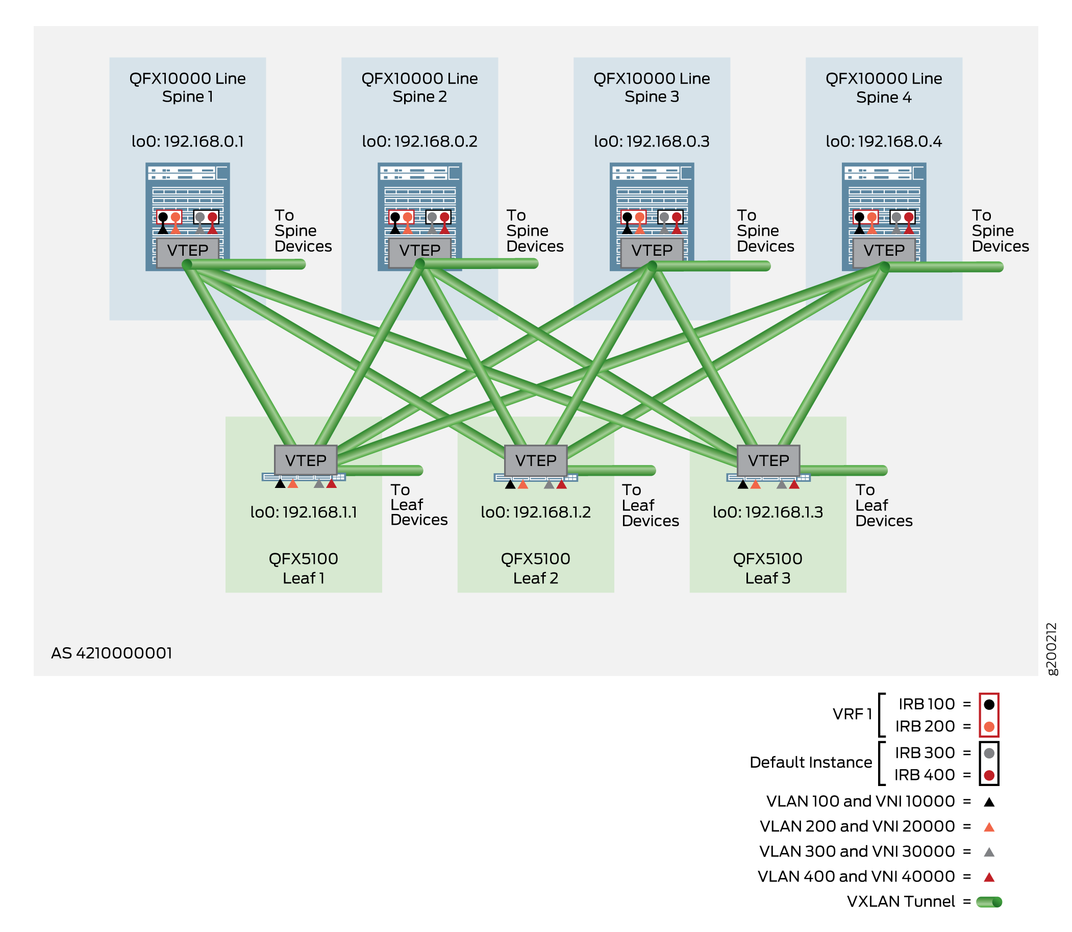
As shown in Figure 2, you configure VLANs
at the leaf devices, and IRB interfaces for routing at the spine devices. Such configuration
is placed in the default switching instance at the [edit vlans],
[edit interfaces], [edit protocols evpn], and
[edit switch-options] hierarchy levels. Routing instances are not
required for this overlay style, but can be implemented as an option depending on the needs
of your network.
When you implement this style of overlay on a spine device, you:
-
Configure IRB interfaces to route traffic between Ethernet virtual network instances.
-
Set virtual gateway addresses.
-
Add VXLAN features to optimize traffic paths.
-
Configure EVPN with VXLAN encapsulation in the default switching instance or in a routing instance.
-
Set the loopback interface as the VTEP source interface.
-
Configure route distinguishers and route targets to direct traffic to peers.
-
Map VLANs to VNIs.
When you implement this style of overlay on a leaf device, you:
-
Configure Ethernet Segment Identifier (ESI) settings.
-
Enable EVPN with VXLAN encapsulation in the default switching instance.
-
Establish route targets and route distinguishers.
-
Map VLANs to VNIs.
For an overview of VLAN-aware CRB overlays, see the Centrally-Routed Bridging Overlay section in Data Center Fabric Blueprint Architecture Components.
If you need to implement more than 4094 VLANs, you can use a CRB overlay with virtual switches (available on switches in the QFX10000 line) or MAC-VRF instances. See Configuring a VLAN-Aware CRB Overlay with Virtual Switches or MAC-VRF Instances. With MAC-VRF instances, you expand your options to either isolate traffic between tenant systems or to enable routing and forwarding between tenant systems.
The following sections provide the detailed steps of how to configure and verify the VLAN-aware CRB overlay in the default switching instance:
- Configuring a VLAN-Aware CRB Overlay in the Default Instance on the Spine Device
- Verifying the VLAN-Aware CRB Overlay in the Default Instance for the Spine Device
- Configuring a VLAN-Aware CRB Overlay in the Default Instance on the Leaf Device
- Verifying the VLAN-Aware CRB Overlay in the Default Instance for the Leaf Device
Configuring a VLAN-Aware CRB Overlay in the Default Instance on the Spine Device
To configure a VLAN-aware CRB overlay in the default switching instance on a spine device, perform the following:
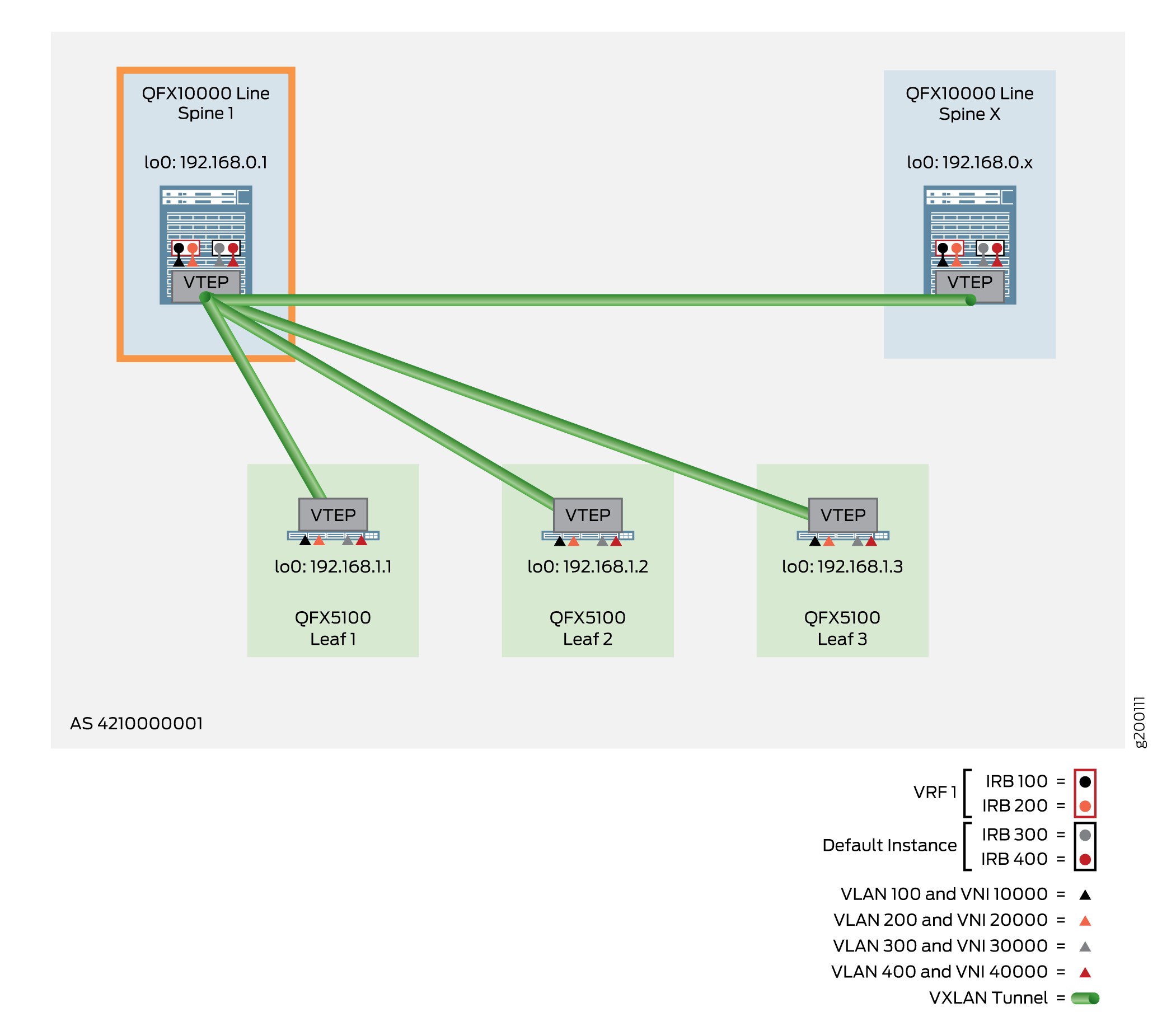
The following example shows the configuration for Spine 1, as shown in Figure 3.
Verifying the VLAN-Aware CRB Overlay in the Default Instance for the Spine Device
Issue the following commands to verify that the overlay is working properly on your spine devices:
Configuring a VLAN-Aware CRB Overlay in the Default Instance on the Leaf Device
To configure a VLAN-aware CRB overlay in the default switching instance on a leaf device, perform the following:
-
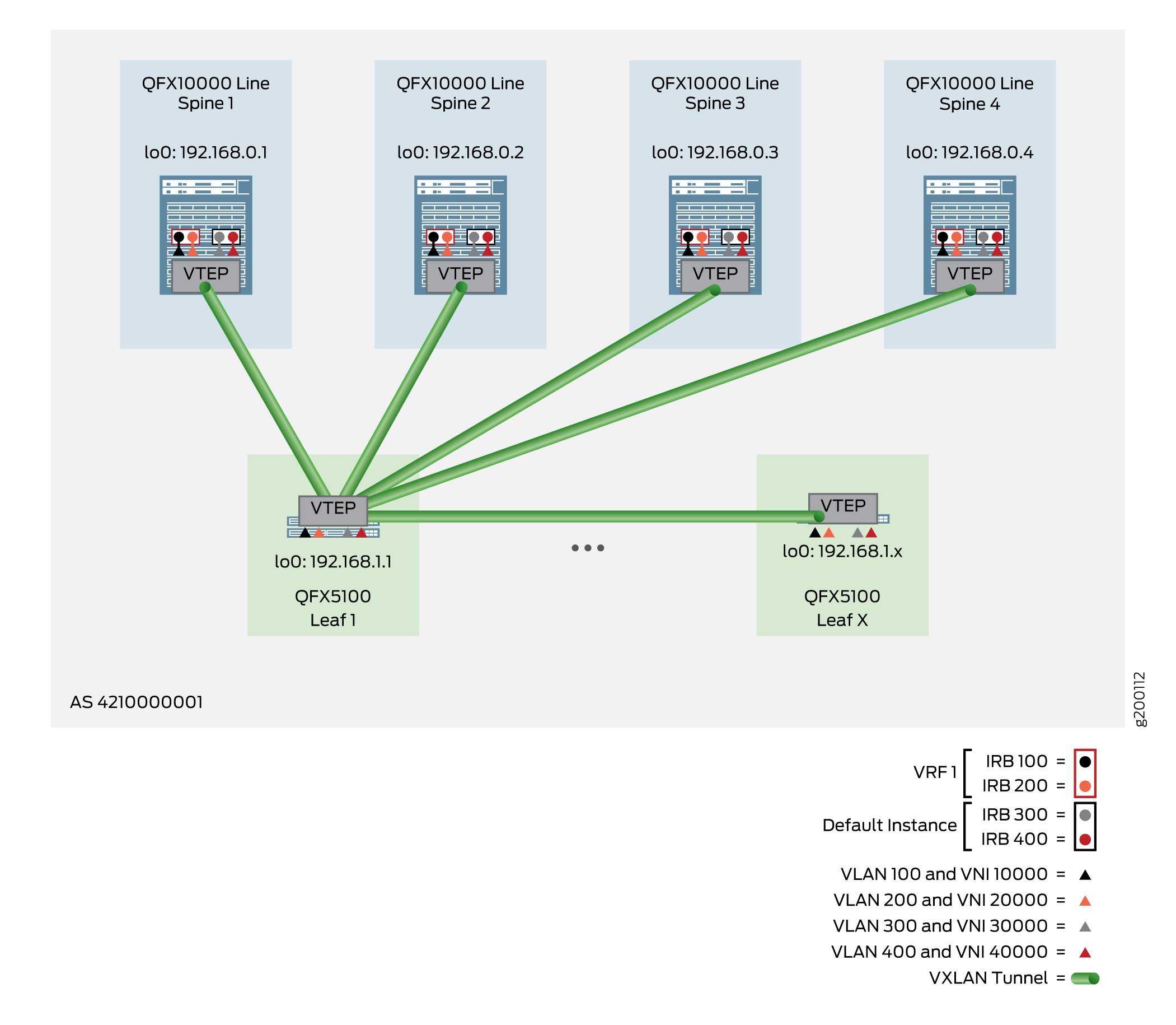
The following example shows the configuration for Leaf 1, as shown in Figure 4.
-
Configure ESI settings on all similar leaf devices. Because the end systems in this
reference design are multihomed to three leaf devices per device type cluster (such as
QFX5100), you must configure the same ESI identifier and LACP system identifier on all
three leaf devices for each unique end system. Unlike other topologies where you would
configure a different LACP system identifier per leaf device and have VXLAN select a
single designated forwarder, use the same LACP system identifier to allow the 3 leaf
devices to appear as a single LAG to a multihomed end
system. In addition, use
the same aggregated Ethernet interface number for all ports included in the ESI.
The configuration for Leaf 1 is shown below, but you must replicate this configuration on both Leaf 2 and Leaf 3 per the topology shown in Figure 5.
Tip:When you create an ESI number, always set the high order octet to 00 to indicate the ESI is manually created. The other 9 octets can be any hexadecimal value from 00 to FF.
Figure 5: ESI Topology for Leaf 1, Leaf 2, and Leaf 3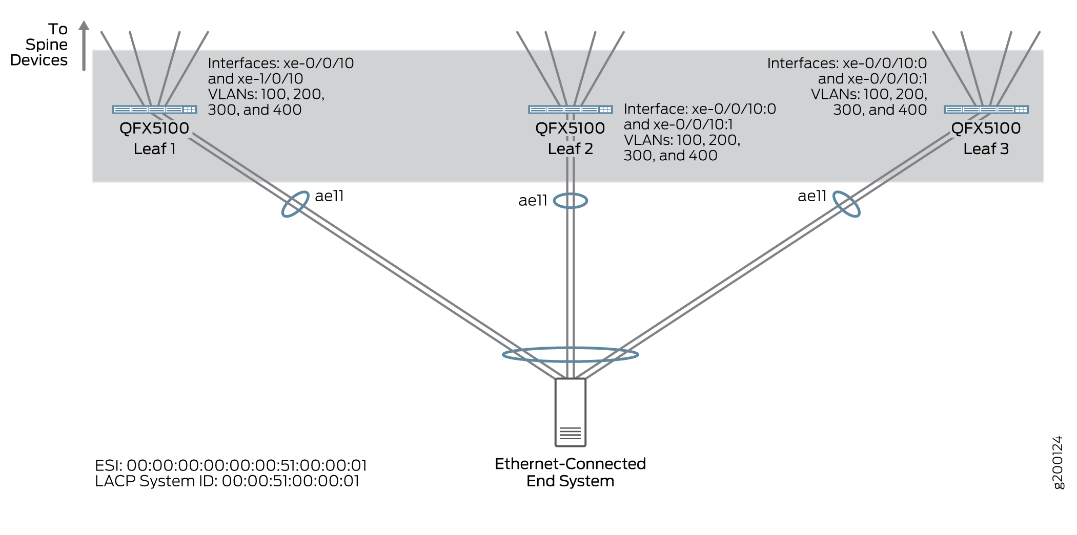
Leaf 1:
set interfaces ae11 esi 00:00:00:00:00:00:51:00:00:01
set interfaces ae11 esi all-active
set interfaces ae11 aggregated-ether-options lacp system-id 00:00:51:00:00:01
set interfaces xe-0/0/10 ether-options 802.3ad ae11
set interfaces xe-1/0/10 ether-options 802.3ad ae11
Verifying the VLAN-Aware CRB Overlay in the Default Instance for the Leaf Device
Issue the following commands to verify that the overlay is working properly on your leaf devices:
See Also
Configuring a VLAN-Aware CRB Overlay with Virtual Switches or MAC-VRF Instances
You can configure a VLAN-aware CRB overlay model using virtual switches or MAC-VRF instances. With either of these models, you can configure multiple switching instances where each switching instance can support up to 4094 VLANs per instance.
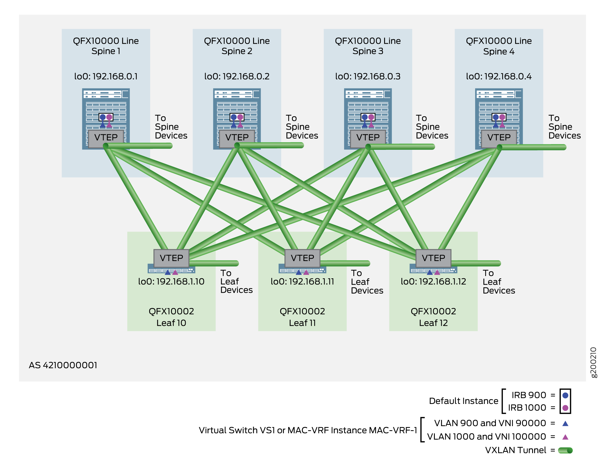
The configuration method for VLANs (at the leaf devices) and IRB interfaces (at the spine devices) is similar to the default instance method for VLAN-aware CRB overlays. The main difference is that you configure certain elements inside the virtual switching instances or MAC-VRF instances. See Figure 6.
When you implement this style of overlay on a spine device, you:
-
Configure a virtual switch or MAC-VRF instance with:
-
The loopback interface as the VTEP source interface.
-
Route distinguishers and route targets.
-
EVPN with VXLAN encapsulation.
-
VLAN to VNI mappings and Layer 3 IRB interface associations.
-
-
Configure virtual gateways, virtual MAC addresses, and corresponding IRB interfaces (to provide routing between VLANs).
To implement this overlay style on a leaf device:
-
Configure a virtual switch or a MAC-VRF instance with:
-
The loopback interface as the VTEP source interface.
-
Route distinguishers and route targets.
-
EVPN with VXLAN encapsulation.
-
VLAN to VNI mappings.
-
-
Set the following end system-facing elements:
-
An Ethernet segment ID (ESI).
-
Flexible VLAN tagging and extended VLAN bridge encapsulation.
-
LACP settings.
-
VLAN IDs.
-
For an overview of VLAN-aware CRB overlays, see the Centrally-Routed Bridging Overlay section in Data Center Fabric Blueprint Architecture Components.
For information on MAC-VRF instances, see MAC-VRF Instances for Multitenancy in Network Virtualization Overlays and MAC-VRF Routing Instance Type Overview.
-
For a simpler method that works on all leaf platforms used in this reference design, see Configuring a VLAN-Aware CRB Overlay in the Default Instance
The following sections provide the detailed steps of how to configure and verify the VLAN-aware CRB overlay with virtual switches or MAC-VRF instances.
- Configuring the VLAN-Aware CRB Overlay with Virtual Switches or MAC-VRF Instances on a Spine Device
- Verifying the VLAN-Aware Model for a CRB Overlay with Virtual Switches or MAC-VRF Instances on a Spine Device
- Configuring the VLAN-Aware CRB Overlay with Virtual Switches or MAC-VRF Instances on a Leaf Device
- Verifying the VLAN-Aware CRB Overlay with Virtual Switches or MAC-VRF Instances on a Leaf Device
Configuring the VLAN-Aware CRB Overlay with Virtual Switches or MAC-VRF Instances on a Spine Device
To configure a VLAN-aware style of CRB overlay on a spine device, perform the following:
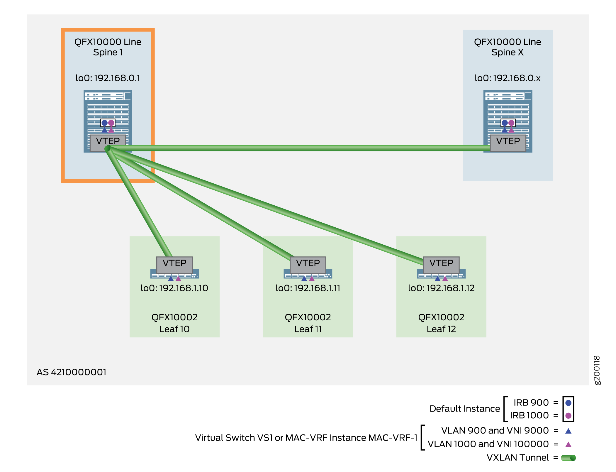
The following example shows the configuration for Spine 1, as shown in Figure 7.
Verifying the VLAN-Aware Model for a CRB Overlay with Virtual Switches or MAC-VRF Instances on a Spine Device
To verify this style of overlay on a spine device, run the commands in this section.
Most commands here show output for a virtual switch instance configuration. With a MAC-VRF instance configuration, you can alternatively use:
-
show mac-vrf forwardingcommands that are aliases for theshow ethernet-switchingcommands in this section. -
The
show mac-vrf routing databasecommand, which is an alias for theshow evpn databasecommand in this section. -
The
show mac-vrf routing instancecommand, which is an alias for theshow evpn instancecommand in this section.
See MAC-VRF Routing Instance Type Overview for tables of show mac-vrf
forwarding and show ethernet-switching command mappings, and
show mac-vrf routing command aliases for show evpn
commands.
Otherwise, you can use the commands in this section for either virtual switch instances or MAC-VRF instances.
The output with a MAC-VRF instance configuration displays similar information for MAC-VRF routing instances as this section shows for virtual switch instances. One main difference you might see is in the output with MAC-VRF instances on devices where you enable the shared tunnels feature. With shared tunnels enabled, you see VTEP interfaces in the following format:
vtep-index.shared-tunnel-unit
where:
-
index is the index associated with the MAC-VRF routing instance.
-
shared-tunnel-unit is the unit number associated with the shared tunnel remote VTEP logical interface.
For example, if a device has a MAC-VRF instance with index 26 and the instance connects to two remote VTEPs, the shared tunnel VTEP logical interfaces might look like this:
vtep-26.32823
vtep-26.32824
Configuring the VLAN-Aware CRB Overlay with Virtual Switches or MAC-VRF Instances on a Leaf Device
To configure a VLAN-aware CRB overlay in a virtual switch or a MAC-VRF instance on a leaf device, perform the following:
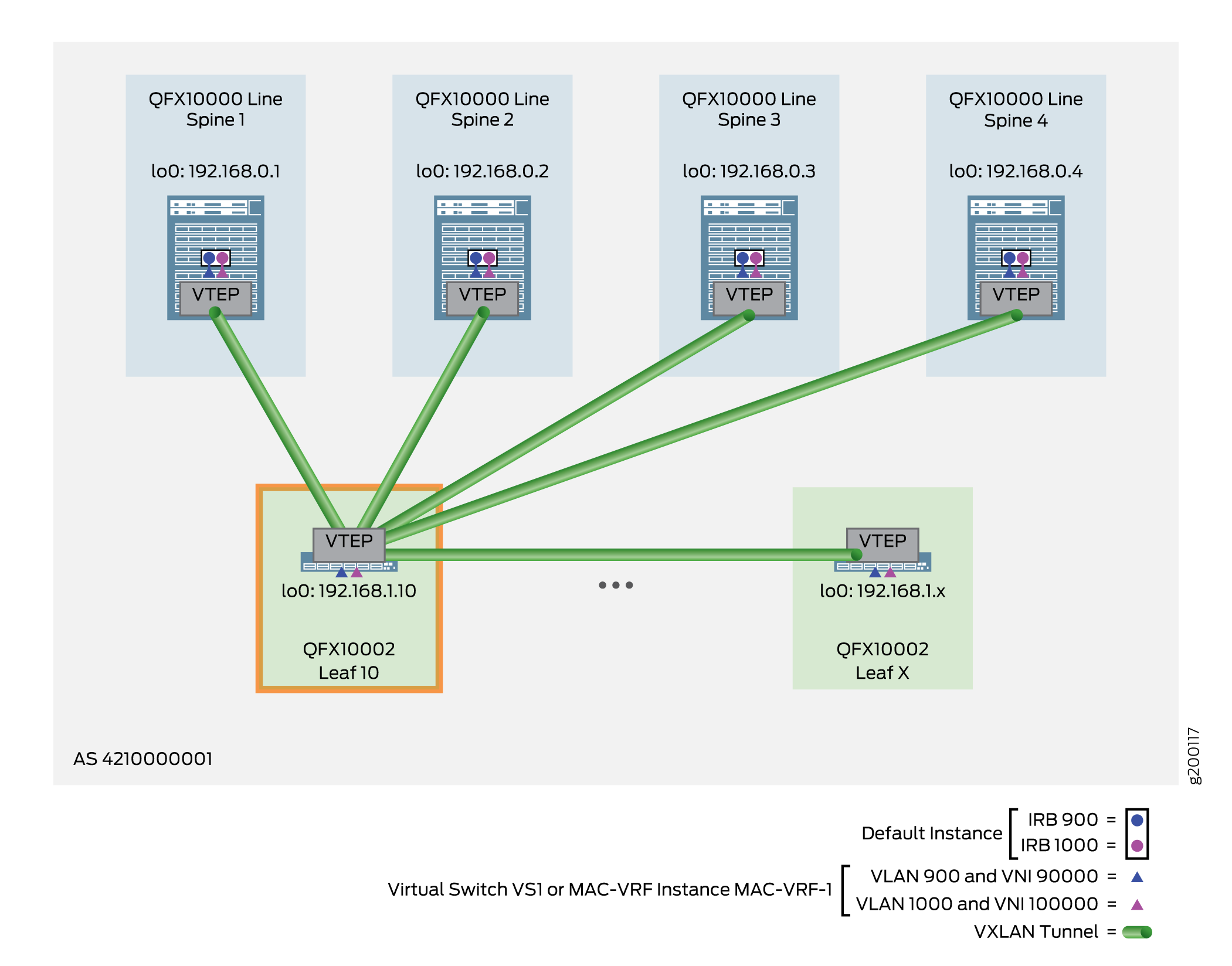
The following example shows the configuration for Leaf 10, as shown in Figure 8.
-
Configure the leaf device to communicate with the end system. In this example,
configure an aggregated Ethernet interface on Leaf 10—in this case, ae12 with two
member interfaces. With the interface definition, include LACP options, an ESI in
all-active mode, and VLANs 900 and 1000 (which this example uses for the VLAN-aware
service type). Figure 9 illustrates the
topology.
Figure 9: ESI Topology for Leaf 10, Leaf 11, and Leaf 12
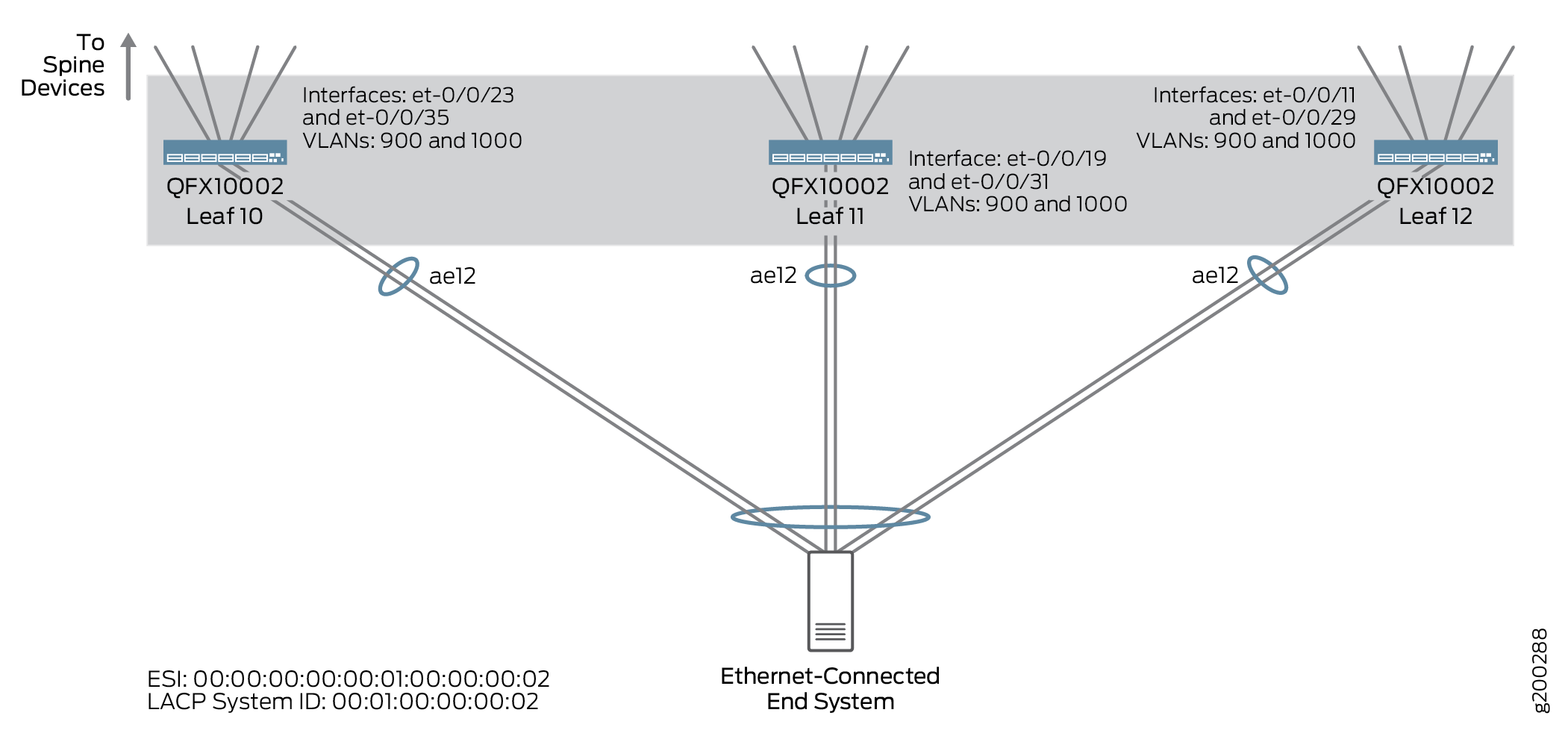
Leaf 10:
set interfaces ae12 flexible-vlan-tagging
set interfaces ae12 encapsulation extended-vlan-bridge
set interfaces ae12 esi 00:00:00:00:00:01:00:00:00:02
set interfaces ae12 esi all-active
set interfaces ae12 aggregated-ether-options minimum-links 1
set interfaces ae12 aggregated-ether-options lacp active
set interfaces ae12 aggregated-ether-options lacp periodic fast
set interfaces ae12 aggregated-ether-options lacp system-id 00:01:00:00:00:02
set interfaces ae12 aggregated-ether-options lacp hold-time up 300
set interfaces ae12 unit 900 vlan-id 900
set interfaces ae12 unit 1000 vlan-id 1000
set interfaces et-0/0/23 ether-options 802.3ad ae12
set interfaces et-0/0/35 ether-options 802.3ad ae12
Note that in this example, you configure the aggregated Ethernet interface to support the service provider configuration style. See Flexible Ethernet Service Encapsulation for more information on the service provider style configuration for switch interfaces.
Verifying the VLAN-Aware CRB Overlay with Virtual Switches or MAC-VRF Instances on a Leaf Device
To verify this style of overlay on a leaf device, run the commands in this section.
Most commands here show output for a virtual switch instance configuration. With a MAC-VRF instance configuration, you can alternatively use:
-
show mac-vrf forwardingcommands that are aliases for theshow ethernet-switchingcommands in this section. -
The
show mac-vrf routing instancecommand, which is an alias for theshow evpn instancecommand in this section.
See MAC-VRF Routing Instance Type Overview for tables of show mac-vrf
forwarding and show ethernet-switching command mappings, and
show mac-vrf routing command aliases for show evpn
commands.
Otherwise, you can use the commands in this section for either virtual switch instances or MAC-VRF instances.
The output with a MAC-VRF instance configuration displays similar information for MAC-VRF routing instances as this section shows for virtual switch instances. One main difference you might see is in the output with MAC-VRF instances on devices where you enable the shared tunnels feature. With shared tunnels enabled, you see VTEP interfaces in the following format:
vtep-index.shared-tunnel-unit
where:
-
index is the index associated with the MAC-VRF routing instance.
-
shared-tunnel-unit is the unit number associated with the shared tunnel remote VTEP logical interface.
For example, if a device has a MAC-VRF instance with index 26 and the instance connects to two remote VTEPs, the shared tunnel VTEP logical interfaces might look like this:
vtep-26.32823
vtep-26.32824
See Also
Centrally-Routed Bridging Overlay — Release History
Table 1 provides a history of all of the features in this section and their support within this reference design.
|
Release |
Description |
|---|---|
|
19.1R2 |
QFX10002-60C and QFX5120-32C switches running Junos OS Release 19.1R2 and later releases in the same release train support all features documented in this section. |
|
17.3R3-S2 |
Adds support for Contrail Enterprise Multicloud, where you can configure CRB overlays from the Contrail Command GUI. |
|
17.3R3-S1 |
All devices in the reference design that support Junos OS Release 17.3R3-S1 and later releases in the same release train also support all features documented in this section |