Example: Configuring an ESI on a Logical Interface With EVPN-MPLS Multihoming
When a customer edge (CE) device in an Ethernet VPN-Multiprotocol Label Switching (EVPN-MPLS) environment is multihomed to two or more provider edge (PE) devices, the set of Ethernet links that connect the devices comprise an Ethernet segment. An Ethernet segment identifier (ESI) is a 10-octet integer that identifies this segment. A sample ESI is 00:11:22:33:44:55:66:77:88:99.
In releases before Junos OS Release 15.1F6 and 16.1R4 for MX Series routers and in releases before Junos OS Release 17.3R1 for EX9200 switches, you can specify an ESI only on a physical or aggregated Ethernet interface, for example, set interfaces ae0 esi 00:11:22:33:44:55:66:77:88:99. If you specify an ESI on a physical or aggregated Ethernet interface, keep in mind that an ESI is a factor in the designated forwarder (DF) election process. For example, assume that you configure EVPN multihoming active-standby on aggregated Ethernet interface ae0, and given the ESI configured on ae0 and other determining factors, the DF election results in ae0 being in the down state. Further, all logical interfaces configured on ae0, for example, set interfaces ae0 unit 1 and set interfaces ae0 unit 2 are also in the down state, which renders logical interfaces ae0.1 and ae0.2 unable to provide services to their respective customer sites (VLANs).
You can specify an ESI on a logical interface. If you specify an ESI on a logical interface, the DF election process now occurs at the individual logical interface level, which enables you to better utilize logical interfaces. For example, assume that you configure logical interfaces ae0.1 and ae0.2 on aggregated Ethernet interface ae0. You configure EVPN multihoming active-standby on both logical interfaces and given the ESI configured on ae0.1 and other determining factors, the DF election results in ae0.1 being in the down state. Despite logical interface ae0.1 being down, logical interface ae0.2 and other logical interfaces configured on ae0 can be in the up state and provide services to their respective customer sites (VLANs).
This topic shows how to configure an ESI on logical interfaces in both EVPN multihoming active-standby and active-active modes.
We support active-standby multihoming in EVPN fabrics only with MPLS.
Please refer to EVPN-MPLS: Single-active multihoming support for a complete list of the products that support this feature.
Requirements
Both EVPN multihoming active-standby and multihoming active-active examples use the following hardware and software components:
-
An EX9200 switch running Junos OS Release 17.3R1 or later (PE1)
-
An MX Series router running Junos OS Release 15.1F6 or later, or Junos OS Release 17.1R1 or later (PE2)
Overview and Topology
EVPN Multihoming Active-Standby
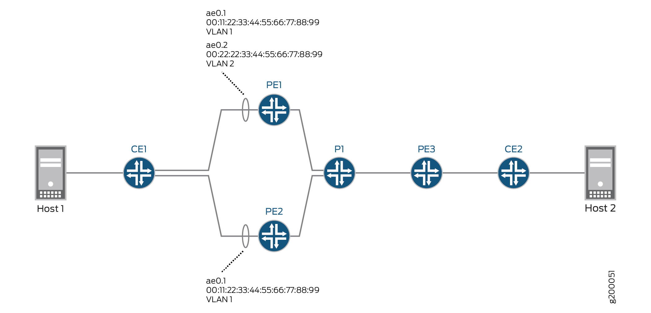
Figure 1 shows an EVPN-MPLS topology in which CE1 is multihomed to PE1 and PE2 to provide redundant paths to CE2. On CE1, the connections to PE1 and PE2 are configured as separate aggregated Ethernet interfaces. Table 1 shows how the connections with CE1 are configured on PE1 and PE2. Note that the EVPN multihoming mode, ESI, and VLAN ID are actually configured on logical interfaces ae0.1 on each PE device.
|
Device |
Physical Interface |
Aggregated Ethernet Interface |
Logical Interface |
EVPN Multihoming Mode |
ESI |
VLAN ID |
|---|---|---|---|---|---|---|
|
PE1 |
xe-2/0/0 |
ae0 |
ae0.1 |
single-active |
00:11:22:33:44:55:66:77:88:99 |
1 |
|
PE2 |
xe-3/0/2 |
ae0 |
ae0.1 |
single-active |
00:11:22:33:44:55:66:77:88:99 |
1 |
Based on the DF election, logical interface ae0.1 on PE2 is up, and logical interface ae0.1 on PE1 is down.
Table 2 also shows the configuration for logical interface ae0.2 on PE1. Note that logical interface ae0.2 provides services for a different VLAN and is configured with a different ESI than logical interface ae0.1, which is configured on the same aggregated Ethernet interface. As a result, logical interface ae0.2 is up and providing services to VLAN 2 despite the fact that logical interface ae0.1 is in the down state.
|
Device |
Physical Interface |
Aggregated Ethernet Interface |
Logical Interface |
EVPN Multihoming Mode |
ESI |
VLAN ID |
|---|---|---|---|---|---|---|
|
PE1 |
xe-2/0/0 |
ae0 |
ae0.2 |
single-active |
00:22:22:33:44:55:66:77:88:99 |
2 |
EVPN Multihoming Active-Active
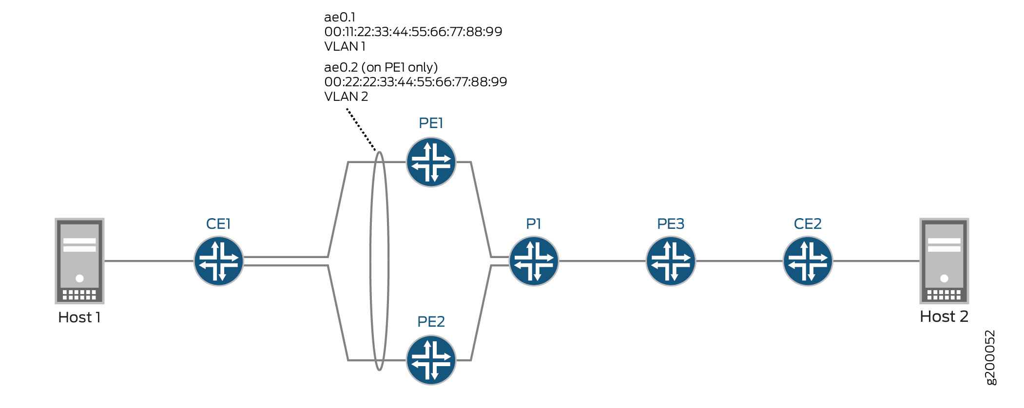
Figure 2 shows an EVPN-MPLS topology in which CE1 is multihomed to PE1 and PE2 to provide redundant paths to CE2. On CE1, the connections to PE1 and PE2 are configured as one aggregated Ethernet interface. Table 3 shows how the connections with CE1 are configured on PE1 and PE2. Note that the EVPN multihoming mode, ESI, and VLAN ID are actually configured on logical interfaces ae0.1 on each device.
|
Device |
Physical Interface |
Aggregated Ethernet Interface |
Logical Interface |
EVPN Multihoming Mode |
ESI |
VLAN ID |
|---|---|---|---|---|---|---|
|
PE1 |
xe-2/0/0 |
ae0 |
ae0.1 |
all-active |
00:11:22:33:44:55:66:77:88:99 |
1 |
|
PE2 |
xe-3/0/2 |
ae0 |
ae0.1 |
all-active |
00:11:22:33:44:55:66:77:88:99 |
1 |
Based on the DF election, logical interface ae0.1 on PE1 is in the up state, and logical interface ae0.1 on PE2 is in the down state.
Table 4 also shows the configuration for logical interface ae0.2 on PE1. Note that logical interface ae0.2 provides services for a different VLAN and is configured with a different ESI than logical interface ae0.1, which is in the same aggregated Ethernet interface. As a result, logical interface ae0.2 is down and unable to provide services to VLAN 2 despite the fact that logical interface ae0.1 is in the up state.
|
Device |
Physical Interface |
Aggregated Ethernet Interface |
Logical Interface |
EVPN Multihoming Mode |
ESI |
VLAN ID |
|---|---|---|---|---|---|---|
|
PE1 |
xe-2/0/0 |
ae0 |
ae0.2 |
all-active |
00:22:22:33:44:55:66:77:88:99 |
2 |
EVPN Multihoming Active-Standby Configuration
The configurations for PE1 (EX9200) and PE2 (MX Series router) focus on configuring EVPN multhihoming active-standby and ESIs on logical interfaces. The configurations do not include all EVPN-related configurations for physical interfaces, aggregated Ethernet interfaces, logical interfaces, and routing instances. For a more comprehensive configuration of EVPN multhihoming active-standby in an EVPN-MPLS environment, see Example: Configuring Basic EVPN-MPLS Active-Standby Multihoming.
CLI Quick Configuration
PE1
set interfaces xe-2/0/0 gigether-options 802.3ad ae0
set interfaces ae0 flexible-vlan-tagging
set interfaces ae0 encapsulation flexible-ethernet-services
set interfaces ae0 unit 1 encapsulation vlan-bridge
set interfaces ae0 unit 1 vlan-id 1
set interfaces ae0 unit 1 esi 00:11:22:33:44:55:66:77:88:99
set interfaces ae0 unit 1 esi single-active
set interfaces ae0 unit 2 encapsulation vlan-bridge
set interfaces ae0 unit 2 vlan-id 2
set interfaces ae0 unit 2 esi 00:22:22:33:44:55:66:77:88:99
set interfaces ae0 unit 2 esi single-active
set interfaces irb unit 1 family inet address 192.0.2.1/24
set interfaces irb unit 2 family inet address 192.0.2.2/24
set routing-instances blue instance-type evpn
set routing-instances blue vlan-id 1
set routing-instances blue interface ae0.1
set routing-instances blue l3-interface irb.1
...
set routing-instances blue protocols evpn interface ae0.1
set routing-instances green instance-type evpn
set routing-instances green vlan-id 2
set routing-instances green interface ae0.2
set routing-instances green l3-interface irb.2
...
set routing-instances green protocols evpn interface ae0.2
set routing-instances vrf instance-type vrf
set routing-instances vrf interface irb.1
set routing-instances vrf interface irb.2
...
PE2
set interfaces xe-3/0/2 gigether-options 802.3ad ae0
set interfaces ae0 flexible-vlan-tagging
set interfaces ae0 encapsulation flexible-ethernet-services
set interfaces ae0 unit 1 encapsulation vlan-bridge
set interfaces ae0 unit 1 vlan-id 1
set interfaces ae0 unit 1 esi 00:11:22:33:44:55:66:77:88:99
set interfaces ae0 unit 1 esi single-active
set interfaces irb unit 1 family inet address 192.0.2.1/24
set routing-instances blue instance-type evpn
set routing-instances blue vlan-id 1
set routing-instances blue interface ae0.1
set routing-instances blue routing-interface irb.1
...
set routing-instances blue protocols evpn interface ae0.1
set routing-instances vrf instance-type vrf
set routing-instances vrf interface irb.1
...
Procedure
Step-by-Step Procedure
To configure EVPN multihoming active-standby on PE1:
-
Specify an Ethernet interface as a member of aggregated Ethernet interface ae0.
[edit interfaces]
user@switch# set xe-2/0/0 gigether-options 802.3ad ae0
-
Configure aggregated Ethernet interface ae0 to simultaneously transmit 802.1Q VLAN single-tag and dual-tag frames and to support different types of Ethernet encapsulation at the logical interface level.
[edit interfaces]
user@switch# set ae0 flexible-vlan-tagging
user@switch# set ae0 encapsulation flexible-ethernet-services
-
On aggregated Ethernet interface ae0, configure logical interfaces ae0.1 and ae0.2. Configure the logical interfaces to use VLAN bridge encapsulation, and map the logical interfaces to VLANs 1 and 2, respectively. Also, assign an ESI to the logical interfaces, and enable EVPN multihoming active-standby.
[edit interfaces]
user@switch# set ae0 unit 1 encapsulation vlan-bridge
user@switch# set ae0 unit 1 vlan-id 1
user@switch# set ae0 unit 1 esi 00:11:22:33:44:55:66:77:88:99
user@switch# set ae0 unit 1 esi single-active
user@switch# set ae0 unit 2 encapsulation vlan-bridge
user@switch# set ae0 unit 2 vlan-id 2
user@switch# set ae0 unit 2 esi 00:22:22:33:44:55:66:77:88:99
user@switch# set ae0 unit 2 esi single-active
-
Configure IRB interfaces irb.1 and irb.2, and assign an IP address to each interface.
[edit interfaces] set interfaces irb unit 1 family inet address 192.0.2.1/24 set interfaces irb unit 2 family inet address 192.0.2.2/24 -
Configure an EVPN routing instance named blue. Map the routing instance to VLAN 1, logical interface ae0.1, and IRB interface irb.1. Configure EVPN logical interface ae0.1 for the EVPN routing instance.
[edit routing-instances]
user@switch# set blue instance-type evpn
user@switch# set blue vlan-id 1
user@switch# set blue interface ae0.1
user@switch# set blue l3-interface irb.1
user@switch# set blue protocols evpn interface ae0.1
-
Configure an EVPN routing instance named green. Map the routing instance to VLAN 2, logical interface ae0.2, and IRB interface irb.2. Configure logical interface ae0.2 for the EVPN routing instance.
[edit routing-instances]
user@switch# set green instance-type evpn
user@switch# set green vlan-id 2
user@switch# set green interface ae0.2
user@switch# set green l3-interface irb.2
user@switch# set green protocols evpn interface ae0.2
-
Configure a VRF routing instance, and add IRB interfaces irb.1 and irb.2 to the routing instance.
[edit routing-instances]
set vrf instance-type vrf


                        set vrf interface irb.1


                        set vrf interface irb.2
Step-by-Step Procedure
To configure EVPN multihoming active-standby on PE2:
-
Specify an Ethernet interface as a member of aggregated Ethernet interface ae0.
[edit interfaces]
user@router# set xe-3/0/2 gigether-options 802.3ad ae0
-
Configure aggregated Ethernet interface ae0 to simultaneously transmit 802.1Q VLAN single-tag and dual-tag frames and to support different types of Ethernet encapsulation at the logical interface level.
[edit interfaces]
user@router# set ae0 flexible-vlan-tagging
user@router# set ae0 encapsulation flexible-ethernet-services
-
On aggregated Ethernet interface ae0, configure logical interface ae0.1. Configure the logical interface to use VLAN bridge encapsulation, and map the logical interface to VLAN 1 and 2. Also, assign an ESI to the logical interface, and enable EVPN multihoming active-standby.
[edit interfaces]
user@router# set ae0 unit 1 encapsulation vlan-bridge
user@router# set ae0 unit 1 vlan-id 1
user@router# set ae0 unit 1 esi 00:11:22:33:44:55:66:77:88:99
user@router# set ae0 unit 1 esi single-active
-
Configure IRB interface irb.1, and assign an IP address to the interface.
[edit interfaces]
user@router# set irb unit 1 family inet address 192.0.2.1/24
-
Configure an EVPN routing instance named blue. Map the routing instance to VLAN 1, logical interface ae0.1, and IRB interface irb.1. Configure EVPN logical interface ae0.1 for the EVPN routing instance.
[edit routing-instances]
user@router# set blue instance-type evpn
user@router# set blue vlan-id 1
user@router# set blue interface ae0.1
user@router# set blue routing-interface irb.1
user@router# set blue protocols evpn interface ae0.1
-
Configure a VRF routing instance, and add IRB interface irb.1 to the routing instance.
[edit routing-instances]
user@router# set vrf instance-type vrf
user@router# set vrf interface irb.1
EVPN Multihoming Active-Active Configuration
CLI Quick Configuration
The configurations for PE1 (EX9200) and PE2 (MX Series router) focus on configuring EVPN multhihoming active-active and ESIs on logical interfaces. The configurations do not include all EVPN-related configurations for physical interfaces, aggregated Ethernet interfaces, logical interfaces, and routing instances. For a more comprehensive configuration of EVPN multhihoming active-active, see Example: Configuring EVPN Active-Active Multihoming. Note that the referenced example shows how to configure ESIs on physical and aggregated Ethernet interfaces.
PE1
set interfaces xe-2/0/0 gigether-options 802.3ad ae0
set interfaces ae0 flexible-vlan-tagging
set interfaces ae0 encapsulation flexible-ethernet-services
set interfaces ae0 unit 1 encapsulation vlan-bridge
set interfaces ae0 unit 1 vlan-id 1
set interfaces ae0 unit 1 esi 00:11:22:33:44:55:66:77:88:99
set interfaces ae0 unit 1 esi all-active
set interfaces ae0 unit 2 encapsulation vlan-bridge
set interfaces ae0 unit 2 vlan-id 2
set interfaces ae0 unit 2 esi 00:22:22:33:44:55:66:77:88:99
set interfaces ae0 unit 2 esi all-active
set interfaces irb unit 1 family inet address 192.0.2.1/24
set interfaces irb unit 2 family inet address 192.0.2.2/24
set routing-instances blue instance-type evpn
set routing-instances blue vlan-id 1
set routing-instances blue interface ae0.1
set routing-instances blue l3-interface irb.1
...
set routing-instances blue protocols evpn interface ae0.1
set routing-instances green instance-type evpn
set routing-instances green vlan-id 2
set routing-instances green interface ae0.2
set routing-instances green l3-interface irb.2
...
set routing-instances green protocols evpn interface ae0.2
set routing-instances vrf instance-type vrf
set routing-instances vrf interface irb.1
set routing-instances vrf interface irb.2
...
PE2
set interfaces xe-3/0/2 gigether-options 802.3ad ae0
set interfaces ae0 flexible-vlan-tagging
set interfaces ae0 encapsulation flexible-ethernet-services
set interfaces ae0 unit 1 encapsulation vlan-bridge
set interfaces ae0 unit 1 vlan-id 1
set interfaces ae0 unit 1 esi 00:11:22:33:44:55:66:77:88:99
set interfaces ae0 unit 1 esi all-active
set interfaces irb unit 1 family inet address 192.0.2.1/24
set routing-instances blue instance-type evpn
set routing-instances blue vlan-id 1
set routing-instances blue interface ae0.1
set routing-instances blue routing-interface irb.1
...
set routing-instances blue protocols evpn interface ae0.1
set routing-instances vrf instance-type vrf
set routing-instances vrf interface irb.1
...
Step-by-Step Procedure
To configure EVPN multihoming active-active on PE1:
-
Specify an Ethernet interface as a member of aggregated Ethernet interface ae0.
[edit interfaces]
user@switch# set xe-2/0/0 gigether-options 802.3ad ae0
-
Configure aggregated Ethernet interface ae0 to simultaneously transmit 802.1Q VLAN single-tag and dual-tag frames and to support different types of Ethernet encapsulation at the logical interface level.
[edit interfaces]
user@switch# set ae0 flexible-vlan-tagging
user@switch# set ae0 encapsulation flexible-ethernet-services
-
On aggregated Ethernet interface ae0, configure logical interfaces ae0.1 and ae0.2. Configure the logical interfaces to use VLAN bridge encapsulation, and map the logical interfaces to VLANs 1 and 2, respectively. Also, assign an ESI to the logical interfaces, and enable EVPN multihoming active-active.
[edit interfaces]
user@switch# set ae0 unit 1 encapsulation vlan-bridge
user@switch# set ae0 unit 1 vlan-id 1
user@switch# set ae0 unit 1 esi 00:11:22:33:44:55:66:77:88:99
user@switch# set ae0 unit 1 esi all-active
user@switch# set ae0 unit 2 encapsulation vlan-bridge
user@switch# set ae0 unit 2 vlan-id 2
user@switch# set ae0 unit 2 esi 00:22:22:33:44:55:66:77:88:99
user@switch# set ae0 unit 2 esi all-active
-
Configure IRB interfaces irb.1 and irb.2, and assign an IP address to each interface.
[edit interfaces] set interfaces irb unit 1 family inet address 192.0.2.1/24 set interfaces irb unit 2 family inet address 192.0.2.2/24 -
Configure an EVPN routing instance named blue. Map the routing instance to VLAN 1, logical interface ae0.1, and IRB interface irb.1. Configure logical interface ae0.1 for the EVPN routing instance.
[edit routing-instances]
user@switch# set blue instance-type evpn
user@switch# set blue vlan-id 1
user@switch# set blue interface ae0.1
user@switch# set blue l3-interface irb.1
user@switch# set blue protocols evpn interface ae0.1
-
Configure an EVPN routing instance named green. Map the routing instance to VLAN 2, logical interface ae0.2, and IRB interface irb.2. Configure logical interface ae0.2 for the EVPN routing instance.
[edit routing-instances]
user@switch# set green instance-type evpn
user@switch# set green vlan-id 2
user@switch# set green interface ae0.2
user@switch# set green l3-interface irb.2
user@switch# set green protocols evpn interface ae0.2
-
Configure a VRF routing instance, and add IRB interfaces irb.1 and irb.2 to the routing instance.
[edit routing-instances]
set vrf instance-type vrf
set vrf interface irb.1
set vrf interface irb.2
Step-by-Step Procedure
To configure EVPN multihoming active-active on PE2:
-
Specify Ethernet interface xe-3/0/2 as a member of aggregated Ethernet interface ae0.
[edit interfaces]
user@router# set xe-3/0/2 gigether-options 802.3ad ae0
-
Configure aggregated Ethernet interface ae0 to simultaneously transmit 802.1Q VLAN single-tag and dual-tag frames and to support different types of Ethernet encapsulation at the logical interface level.
[edit interfaces]
user@router# set ae0 flexible-vlan-tagging
user@router# set ae0 encapsulation flexible-ethernet-services
-
On aggregated Ethernet interface ae0, configure logical interface ae0.1. Configure the logical interface to use VLAN bridge encapsulation, and map the logical interface to VLANs 1. Also, assign an ESI to the logical interface, and enable EVPN multihoming active-active.
[edit interfaces]
user@router# set ae0 unit 1 encapsulation vlan-bridge
user@router# set ae0 unit 1 vlan-id 1
user@router# set ae0 unit 1 esi 00:11:22:33:44:55:66:77:88:99
user@router# set ae0 unit 1 esi all-active
-
Configure IRB interface irb.1, and assign an IP address to the interface.
[edit interfaces]
user@router# set irb unit 1 family inet address 192.0.2.1/24
-
Configure an EVPN routing instance named blue. Map the routing instance to VLAN 1, logical interface ae0.1, and IRB interface irb.1. Configure logical interface ae0.1 for the EVPN routing instance.
[edit routing-instances]
user@router# set blue instance-type evpn
user@router# set blue vlan-id 1
user@router# set blue interface ae0.1
user@router# set blue routing-interface irb.1
user@router# set blue protocols evpn interface ae0.1
-
Configure a VRF routing instance, and add IRB interface irb.1 to the routing instance.
[edit routing-instances]
user@router# set vrf instance-type vrf
user@router# set vrf interface irb.1
Verification
- Verifying that a Logical Interface Has Correct ESI and EVPN Multihoming Mode
- Verifying the EVPN Routing Instance Status
Verifying that a Logical Interface Has Correct ESI and EVPN Multihoming Mode
Purpose
Verify that logical interface ae0.1 is configured with the correct ESI and EVPN multihoming mode.
Action
From operational mode, enter the show interfaces ae0.1 command.
user@switch>  show interfaces ae0.1
    Logical interface ae0.1 (Index 332) (SNMP ifIndex 706)
    Flags: Up SNMP-Traps 0x20004000 VLAN-Tag [ 0x8100.100 ]  Encapsulation: VLAN-Bridge
    Input packets : 0
    Output packets: 0
    Protocol bridge, MTU: 1522
      Flags: Is-Primary
Ethernet segment value: 00:11:22:33:44:55:66:77:88:99, Mode: Single-active
Meaning
The output shows that logical interface ae0.1 is configured with ESI 00:11:22:33:44:55:66:77:88:99 and the EVPN multihoming mode is single-active for multihoming active-standby mode. For a scenario with multihoming active-active mode, the output would display all-active.
Verifying the EVPN Routing Instance Status
Purpose
Verify the status of the various elements configured in an EVPN routing instance.
Action
From operational mode, enter the show evpn instance extensive command.
user@switch>  show evpn instance extensive
  Instance: blue
  ...
  Number of local interfaces:  (1 up)
    Interface name  ESI                            Mode             Status     AC-Role
    ae0.1           00:11:22:33:44:55:066:77:88:99  single-active       Up         Root
  Number of IRB interfaces: 1 (1 up)
    Interface name  VLAN ID  Status  L3 context
    irb.1           1      Up      vrf
  Number of protect interfaces: 0
  Number of bridge domains: 1
    VLAN  Domain ID   Intfs / up    IRB intf   Mode             MAC sync  IM route label  SG sync  IM core nexthop
    1                    0    0                Local switching
   ...
  Number of ethernet segments: 1
    ESI: 00:11:22:33:44:55:066:77:88:99
      Status: Resolved by IFL ae0.1
      Local interface: ae0.1, Status: Up/Forwarding
      Number of remote PEs connected: 1
        Remote PE        MAC label  Aliasing label  Mode
        10.255.0.1       0          300928          all-active
      DF Election Algorithm: MOD based
      Designated forwarder: 10.255.0.1
      Backup forwarder: 10.255.0.2
      Last designated forwarder update: Jul 28 13:04:29
      Advertised split horizon label: 300128
Meaning
The output shows that for the EVPN routing instance named blue, the logical interface ae0.1 and IRB interface irb.1 are up and running. It also shows that VLAN 1 and Ethernet segment 00:11:22:33:44:55:066:77:88:99 are properly mapped to the routing instance. It also shows the status of the DF election.
Change History Table
Feature support is determined by the platform and release you are using. Use Feature Explorer to determine if a feature is supported on your platform.