Example: Configuring Basic EVPN-MPLS Active-Standby Multihoming
This example shows how to configure active-standby multihoming in an Ethernet VPN (EVPN) fabric with MPLS.
Requirements
This example uses the following hardware and software components:
-
Four MX Series 5G Universal Routing Platforms running Junos OS Release 14.1 (or later), with MPC interfaces, acting as provider edge (PE) and provider (P) routers.
-
Two customer edge (CE) devices.
We support active-standby multihoming in EVPN fabrics only with MPLS.
Please refer to EVPN-MPLS: Single-active multihoming support for a complete list of the products that support this feature.
Overview and Topology
Figure 1 illustrates a simple EVPN topology. Routers PE1 and PE2 are provider edge (PE) routers connected to multihomed customer edge (CE) router CE1. An additional PE, router PE3, is a remote PE in the EVPN fabric connected to CE2, a single-homed CE router.
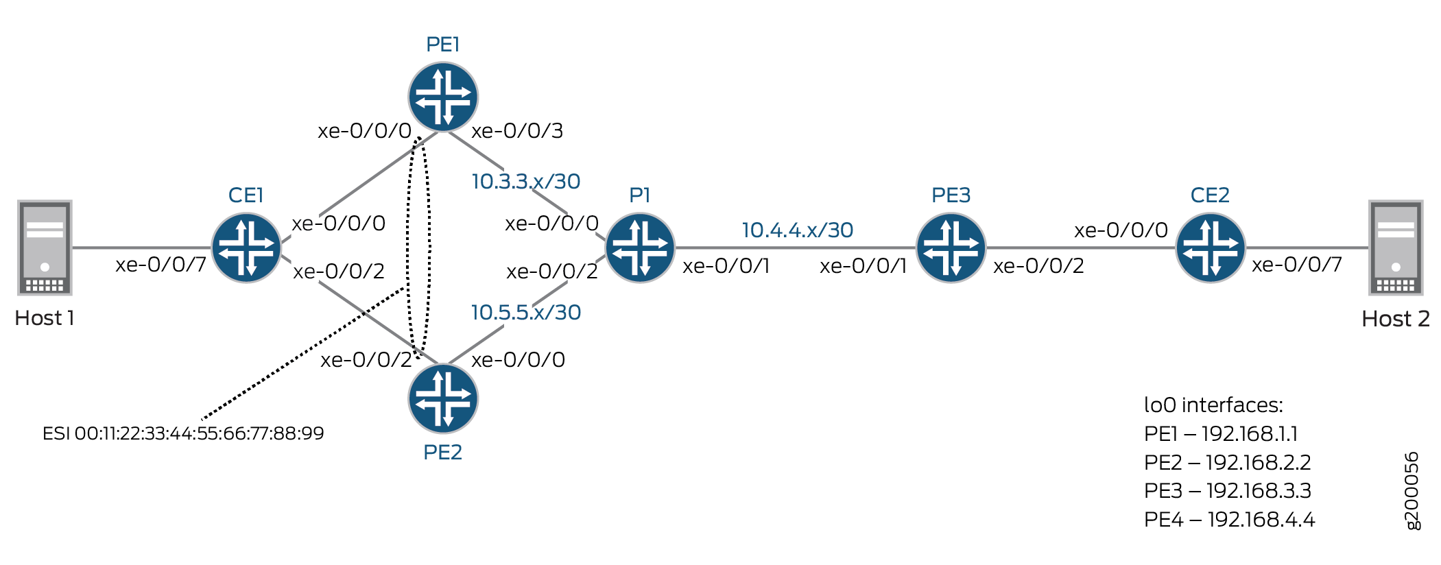
The network has the following characteristics:
-
All PE and P routers are running OSPF.
-
There is an IBGP mesh between all PE routers.
-
MPLS (RSVP) LSPs are configured between all PE routers.
-
On routers PE1 and PE2, each device’s CE-facing interface uses the same Ethernet Segment Identifier (ESI).
For simplicity and consistency of configuration, this example configures the following elements on the three PE devices as part of setting up the EVPN:
-
An EVPN instance (EVI) named EVPN-RI using
instance-type
                            virtual-switch
. The example enablesprotocols evpnin the instance.Note:You can use another instance type instead of
virtual-switchthat the device supports for EVPN instances, such asinstance-type evpn. -
A route distinguisher for the EVI that is unique on each PE device.
-
A route target extended community for the EVPN instance using the
vrf-targetstatement.Note:With this statement, the device automatically sets import and export routing policies based on the specified community. Because this configuration uses the same route target value on all of the PE devices, they can share routes using those implicit routing policies. The example doesn't need to explicitly configure import and export policies for route sharing.
This example configures the following elements on the two multihoming peer PE devices PE1 and PE2 to which CE1 is multihomed:
-
The interfaces that connect to the multihomed CE.
-
An Ethernet Segment (ES) identifier (ESI) associated with those interfaces. The ESI values must match on the multihoming peer PE devices.
-
Single-active mode for ES operation.
See EVPN Multihoming Overview and Configuring EVPN-MPLS Active-Standby Multihoming for more detail on the required configuration elements and steps.
Note that we support configuring the following elements on EVPN PEs, but we don't include them in this configuration because the example focuses only on the basic required elements:
-
In addition to an EVPN instance, you usually configure Layer 3 (L3) VRF (virtual routing and forwarding) routing instances on the EVPN PE devices using the
vrfinstance type. L3 VRF instances enable separation or route sharing among multiple tenants at different sites supported by the PEs in the EVPN fabric. -
If needed, you can configure multiple EVPN instances to set up more than one EVPN with the same set of PEs. In contrast with L3 VRF instances, multiple EVPN instances work at Layer 2 (L2) to further separate how the traffic can be forwarded within or routed between particular VLANs or bridge domains that the EVPN fabric supports.
Configuration
CLI Quick Configuration
The configurations for each device are as follows:
CE1
interfaces {
    xe-0/0/0 {
        description to-PE1;
        unit 0 {
            family bridge {
                interface-mode trunk;
                vlan-id-list 10;
            }
        }
    }
    xe-0/0/2 {
        description to-PE2;
        unit 0 {
            family bridge {
                interface-mode trunk;
                vlan-id-list 10;
            }
        }
    }
    xe-0/0/7 {
        description to-Host;
        unit 0 {
            family bridge {
                interface-mode access;
                vlan-id 10;
            }
        }
    }
}
bridge-domains {
    BD {
        vlan-id-list 10;
        bridge-options {
            no-mac-learning; ## Used with single-active PE configurations, ensures traffic is always flooded to both PEs in case of a DF change.
        }
    }
}
CE2
interfaces {
    xe-0/0/0 {
        description to-PE3;
        unit 0 {
            family bridge {
                interface-mode trunk;
                vlan-id-list 10;
            }
        }
    }
    xe-0/0/7 {
        description to-Host;
        unit 0 {
            family bridge {
                interface-mode access;
                vlan-id 10;
            }
        }
    }
}
bridge-domains {
    BD {
        vlan-id-list 10;
    }
}
PE1
interfaces {
    xe-0/0/0 {
        description to-CE1;
        flexible-vlan-tagging;
        encapsulation flexible-ethernet-services;
        esi {
            00:11:22:33:44:55:66:77:88:99;
            single-active;
        }
        unit 10 {
            family bridge {
                interface-mode trunk;
                vlan-id-list 10;
            }
        }
    }
    xe-0/0/3 {
        description to-P;
        unit 0 {
            family inet {
                address 10.3.3.1/30;
            }
            family mpls;
        }
    }
    lo0 {
        unit 0 {
            family inet {
                address 192.168.1.1/32;
            }
        }
    }
}
routing-options {
    router-id 192.168.1.1;
    autonomous-system 65432;
    forwarding-table {
        export evpn-pplb;
    }
}
protocols {
    rsvp {
        interface xe-0/0/3.0;
    }
    mpls {
        no-cspf;
        label-switched-path PE1-to-PE2 {
            to 192.168.2.2;
        }
        label-switched-path PE1-to-PE3 {
            to 192.168.3.3;
        }
        interface xe-0/0/3.0;
    }
    bgp {
        group EVPN-PE {
            type internal;
            local-address 192.168.1.1;
            family evpn {
                signaling;
            }
            neighbor 192.168.2.2;
            neighbor 192.168.3.3;
        }
    }
    ospf {
        area 0.0.0.0 {
            interface xe-0/0/3.0;
            interface lo0.0;
        }
    }
}
policy-options {
    policy-statement evpn-pplb {
        from protocol evpn;
        then {
            load-balance per-packet;
        }
    }
}
routing-instances {
    EVPN-RI {
        instance-type virtual-switch;
        interface xe-0/0/0.10;
        route-distinguisher 192.168.1.1:10;
        vrf-target target:65432:10;
        protocols {
            evpn {
                extended-vlan-list 10;
            }
        }
        bridge-domains {
            bd10 {
                domain-type bridge;
                vlan-id 10;
            }
        }
    }
}
PE2
interfaces {
    xe-0/0/0 {
        description to-P;
        unit 0 {
            family inet {
                address 10.5.5.1/30;
            }
            family mpls;
        }
    }
    xe-0/0/2 {
        description to-CE1;
        flexible-vlan-tagging;
        encapsulation flexible-ethernet-services;
        esi {
            00:11:22:33:44:55:66:77:88:99;
            single-active;
        }
        unit 10 {
            family bridge {
                interface-mode trunk;
                vlan-id-list 10;
            }
        }
    }
    lo0 {
        unit 0 {
            family inet {
                address 192.168.2.2/32;
            }
        }
    }
}
routing-options {
    router-id 192.168.2.2;
    autonomous-system 65432;
    forwarding-table {
        export evpn-pplb;
    }
}
protocols {
    rsvp {
        interface xe-0/0/0.0;
    }
    mpls {
        no-cspf;
        label-switched-path PE2-to-PE1 {
            to 192.168.1.1;
        }
        label-switched-path PE2-to-PE3 {
            to 192.168.3.3;
        }
        interface xe-0/0/0.0;
    }
    bgp {
        group EVPN-PE {
            type internal;
            local-address 192.168.2.2;
            family evpn {
                signaling;
            }
            neighbor 192.168.1.1;
            neighbor 192.168.3.3;
        }
    }
    ospf {
        area 0.0.0.0 {
            interface xe-0/0/0.0;
            interface lo0.0;
        }
    }
}
policy-options {
    policy-statement evpn-pplb {
        from protocol evpn;
        then {
            load-balance per-packet;
        }
    }
}
routing-instances {
    EVPN-RI {
        instance-type virtual-switch;
        interface xe-0/0/2.10;
        route-distinguisher 192.168.2.2:10;
        vrf-target target:65432:10;
        protocols {
            evpn {
                extended-vlan-list 10;
            }
        }
        bridge-domains {
            bd10 {
                domain-type bridge;
                vlan-id 10;
            }
        }
    }
}
PE3
interfaces {
    xe-0/0/1 {
        description to-P;
        unit 0 {
            family inet {
                address 10.4.4.1/30;
            }
            family mpls;
        }
    }
    xe-0/0/2 {
        description to-CE3;
        flexible-vlan-tagging;
        encapsulation flexible-ethernet-services;
        unit 10 {
            family bridge {
                interface-mode trunk;
                vlan-id-list 10;
            }
        }
    }
    lo0 {
        unit 0 {
            family inet {
                address 192.168.3.3/32;
            }
        }
    }
}
routing-options {
    router-id 192.168.3.3;
    autonomous-system 65432;
    forwarding-table {
        export evpn-pplb;
    }
}
protocols {
    rsvp {
        interface xe-0/0/1.0;
    }
    mpls {
        no-cspf;
        label-switched-path PE3-to-PE1 {
            to 192.168.1.1;
        }
        label-switched-path PE3-to-PE2 {
            to 192.168.2.2;
        }
        interface xe-0/0/1.0;
    }
    bgp {
        group EVPN-PE {
            type internal;
            local-address 192.168.3.3;
            family evpn {
                signaling;
            }
            neighbor 192.168.1.1;
            neighbor 192.168.2.2;
        }
    }
    ospf {
        area 0.0.0.0 {
            interface xe-0/0/1.0;
            interface lo0.0;
        }
    }
}
policy-options {
    policy-statement evpn-pplb {
        from protocol evpn;
        then {
            load-balance per-packet;
        }
    }
}
routing-instances {
    EVPN-RI {
        instance-type virtual-switch;
        interface xe-0/0/2.10;
        route-distinguisher 192.168.3.3:10;
        vrf-target target:65432:10;
        protocols {
            evpn {
                extended-vlan-list 10;
            }
        }
        bridge-domains {
            bd10 {
                domain-type bridge;
                vlan-id 10;
            }
        }
    }
}
P1
interfaces {
    xe-0/0/0 {
        unit 0 {
            family inet {
                address 10.3.3.2/30;
            }
            family mpls;
        }
    }
    xe-0/0/1 {
        unit 0 {
            family inet {
                address 10.4.4.2/30;
            }
            family mpls;
        }
    }
    xe-0/0/2 {
        unit 0 {
            family inet {
                address 10.5.5.2/30;
            }
            family mpls;
        }
    }
    lo0 {
        unit 0 {
            family inet {
                address 192.168.4.4/32;
            }
        }
    }
}
routing-options {
    router-id 192.168.4.4;
    autonomous-system 65432;
}
protocols {
    rsvp {
        interface all;
        interface fxp0.0 {
            disable;
        }
    }
    mpls {
        interface all;
        interface fxp0.0 {
            disable;
        }
    }
    ospf {
        area 0.0.0.0 {
            interface xe-0/0/0.0;
            interface xe-0/0/1.0;
            interface xe-0/0/2.0;
            interface lo0.0;
        }
    }
}
Verification
Confirm that the configuration is working properly.
- Verifying OSPF
- Verifying BGP
- Verifying MPLS
- Verifying EVPN Configuration and Multihoming Status
- Verifying Route Exchange and ESI Autodiscovery
- Verifying Ethernet Segment (ES) Route Exchange
Verifying OSPF
Purpose
Verify that OSPF is working properly.
Action
Verify that Router P1 has adjacencies established with all PE devices.
user@P1> show ospf neighbor

Address          Interface              State     ID               Pri  Dead
10.3.3.1         xe-0/0/0.0             Full      192.168.1.1      128    33
10.4.4.1         xe-0/0/1.0             Full      192.168.3.3      128    38
10.5.5.1         xe-0/0/2.0             Full      192.168.2.2      128    37
Meaning
Adjacencies have been established with the PE devices.
Verifying BGP
Purpose
Verify that BGP is working properly.
Action
Verify that MP-IBGP peerings are established using EVPN signaling between all PE devices.
user@PE1> show bgp summary
Groups: 1 Peers: 2 Down peers: 0
Table          Tot Paths  Act Paths Suppressed    History Damp State    Pending
bgp.evpn.0
                       4          4          0          0          0          0
Peer                     AS      InPkt     OutPkt    OutQ   Flaps Last Up/Dwn State|#Active/Received/Accepted/Damped...
192.168.2.2           65432         89         55       0       1       22:18 Establ
  EVPN-RI.evpn.0: 2/2/2/0
  bgp.evpn.0: 3/3/3/0
  __default_evpn__.evpn.0: 1/1/1/0
192.168.3.3           65432         59         48       0       1       22:18 Establ
  EVPN-RI.evpn.0: 1/1/1/0
  bgp.evpn.0: 1/1/1/0
  __default_evpn__.evpn.0: 0/0/0/0


user@PE2> show bgp summary

Groups: 1 Peers: 2 Down peers: 0
Table          Tot Paths  Act Paths Suppressed    History Damp State    Pending
bgp.evpn.0
                       5          5          0          0          0          0
Peer                     AS      InPkt     OutPkt    OutQ   Flaps Last Up/Dwn State|#Active/Received/Accepted/Damped...
192.168.1.1           65432         80         50       0       1       22:49 Establ
  bgp.evpn.0: 4/4/4/0
  EVPN-RI.evpn.0: 3/3/3/0
  __default_evpn__.evpn.0: 1/1/1/0
192.168.3.3           65432         73         87       0       0       27:26 Establ
  bgp.evpn.0: 1/1/1/0
  EVPN-RI.evpn.0: 1/1/1/0
  __default_evpn__.evpn.0: 0/0/0/0


user@PE3> show bgp summary
Groups: 1 Peers: 2 Down peers: 0
Table          Tot Paths  Act Paths Suppressed    History Damp State    Pending
bgp.evpn.0
                       5          5          0          0          0          0
Peer                     AS      InPkt     OutPkt    OutQ   Flaps Last Up/Dwn State|#Active/Received/Accepted/Damped...
192.168.1.1           65432         66         51       0       1       23:05 Establ
  bgp.evpn.0: 3/3/3/0
  EVPN-RI.evpn.0: 3/3/3/0
  __default_evpn__.evpn.0: 0/0/0/0
192.168.2.2           65432        104         64       0       0       27:42 Establ
  bgp.evpn.0: 2/2/2/0
  EVPN-RI.evpn.0: 2/2/2/0
  __default_evpn__.evpn.0: 0/0/0/0
Meaning
EVPN-signaled MP-IBGP peerings have been established between all PE devices.
Verifying MPLS
Purpose
Verify that MPLS is working properly.
Action
Verify that MPLS LSPs are established between all PE devices.
user@PE1> show mpls lsp
Ingress LSP: 2 sessions
To              From            State Rt P     ActivePath       LSPname
192.168.2.2     192.168.1.1     Up     0 *                      PE1-to-PE2
192.168.3.3     192.168.1.1     Up     0 *                      PE1-to-PE3
Total 2 displayed, Up 2, Down 0

Egress LSP: 2 sessions
To              From            State   Rt Style Labelin Labelout LSPname
192.168.1.1     192.168.2.2     Up       0  1 FF       3        - PE2-to-PE1
192.168.1.1     192.168.3.3     Up       0  1 FF       3        - PE3-to-PE1
Total 2 displayed, Up 2, Down 0

Transit LSP: 0 sessions
Total 0 displayed, Up 0, Down 0


user@PE2> show mpls lsp
Ingress LSP: 2 sessions
To              From            State Rt P     ActivePath       LSPname
192.168.1.1     192.168.2.2     Up     0 *                      PE2-to-PE1
192.168.3.3     192.168.2.2     Up     0 *                      PE2-to-PE3
Total 2 displayed, Up 2, Down 0

Egress LSP: 2 sessions
To              From            State   Rt Style Labelin Labelout LSPname
192.168.2.2     192.168.3.3     Up       0  1 FF       3        - PE3-to-PE2
192.168.2.2     192.168.1.1     Up       0  1 FF       3        - PE1-to-PE2
Total 2 displayed, Up 2, Down 0

Transit LSP: 0 sessions
Total 0 displayed, Up 0, Down 0


user@PE3> show mpls lsp
Ingress LSP: 2 sessions
To              From            State Rt P     ActivePath       LSPname
192.168.1.1     192.168.3.3     Up     0 *                      PE3-to-PE1
192.168.2.2     192.168.3.3     Up     0 *                      PE3-to-PE2
Total 2 displayed, Up 2, Down 0

Egress LSP: 2 sessions
To              From            State   Rt Style Labelin Labelout LSPname
192.168.3.3     192.168.1.1     Up       0  1 FF       3        - PE1-to-PE3
192.168.3.3     192.168.2.2     Up       0  1 FF       3        - PE2-to-PE3
Total 2 displayed, Up 2, Down 0

Transit LSP: 0 sessions
Total 0 displayed, Up 0, Down 0
Meaning
LSPs have been established between PE devices.
Verifying EVPN Configuration and Multihoming Status
Purpose
Verify that EVPN is configured properly.
Action
Verify that the EVPN routing instances and ESIs are configured and functioning correctly, and confirm that single-active multihoming is enabled.
user@PE1> show evpn instance EVPN-RI extensive
Instance: EVPN-RI
  Route Distinguisher: 192.168.1.1:10
  Per-instance MAC route label: 300128
  MAC database status                     Local  Remote
    MAC advertisements:                       0       0
    MAC+IP advertisements:                    0       0
    Default gateway MAC advertisements:       0       0
  Number of local interfaces: 1 (1 up)
    Interface name  ESI                            Mode         Status    AC-Role
    xe-0/0/0.10     00:11:22:33:44:55:66:77:88:99  single-active   Up       Root
  Number of IRB interfaces: 0 (0 up)
  Number of bridge domains: 1
    VLAN  Domain ID   Intfs / up    IRB intf   Mode        MAC sync  IM route label
    10                   1    1                Extended    Enabled   300240
  Number of neighbors: 2
    Address               MAC    MAC+IP        AD        IM        ES Leaf-label
    192.168.2.2             0         0         1         1         0
    192.168.3.3             0         0         0         1         0
  Number of ethernet segments: 1
    ESI: 00:11:22:33:44:55:66:77:88:99
      Status: Resolved by IFL xe-0/0/0.10
      Local interface: xe-0/0/0.10, Status: Up/Forwarding
      Number of remote PEs connected: 1
        Remote PE        MAC label  Aliasing label  Mode
        192.168.2.2      0          0               single-active


                  Designated forwarder: 192.168.1.1
      Backup forwarder: 192.168.2.2
      Last designated forwarder update: Jun 26 23:30:35
      Advertised MAC label: 300224
      Advertised aliasing label: 300224
      Advertised split horizon label: 300256


user@PE2> show evpn instance EVPN-RI extensive
Instance: EVPN-RI
  Route Distinguisher: 192.168.2.2:10
  Per-instance MAC route label: 300384
  MAC database status                     Local  Remote
    MAC advertisements:                       0       0
    MAC+IP advertisements:                    0       0
    Default gateway MAC advertisements:       0       0
  Number of local interfaces: 1 (1 up)
    Interface name  ESI                              Mode        Status    AC-Role
    xe-0/0/2.10     00:11:22:33:44:55:66:77:88:99  single-active    Up       Root
  Number of IRB interfaces: 0 (0 up)
  Number of bridge domains: 1
    VLAN  Domain ID   Intfs / up    IRB intf   Mode          MAC sync  IM route label
    10                   1    1                Extended      Enabled   300608
  Number of neighbors: 2
    Address               MAC    MAC+IP        AD        IM        ES Leaf-label
    192.168.1.1             0         0         2         1         0
    192.168.3.3             0         0         0         1         0
  Number of ethernet segments: 1
    ESI: 00:11:22:33:44:55:66:77:88:99
      Status: Resolved by NH 1048575
      Local interface: xe-0/0/2.10, Status: Up/Blocking
      Number of remote PEs connected: 1
        Remote PE        MAC label  Aliasing label    Mode
        192.168.1.1      0          300224          single-active


                  Designated forwarder: 192.168.1.1
      Backup forwarder: 192.168.2.2
      Last designated forwarder update: Jun 26 23:30:43
      Advertised MAC label: 300544
      Advertised aliasing label: 300544
      Advertised split horizon label: 300320


user@PE3> show evpn instance EVPN-RI extensive
Instance: EVPN-RI
  Route Distinguisher: 192.168.3.3:10
  Per-instance MAC route label: 300272
  MAC database status                     Local  Remote
    MAC advertisements:                       0       0
    MAC+IP advertisements:                    0       0
    Default gateway MAC advertisements:       0       0
  Number of local interfaces: 1 (1 up)
    Interface name  ESI                            Mode           Status   AC-Role
    xe-0/0/2.10     00:00:00:00:00:00:00:00:00:00  single-homed   Up       Root
  Number of IRB interfaces: 0 (0 up)
  Number of bridge domains: 1
    VLAN  Domain ID   Intfs / up    IRB intf   Mode          MAC sync  IM route label
    10                   1    1                Extended      Enabled   300368
  Number of neighbors: 2
    Address               MAC    MAC+IP        AD        IM        ES Leaf-label
    192.168.1.1             0         0         2         1         0
    192.168.2.2             0         0         1         1         0
  Number of ethernet segments: 1
    ESI: 00:11:22:33:44:55:66:77:88:99
      Status: Resolved by NH 1048574
      Number of remote PEs connected: 2
        Remote PE        MAC label  Aliasing label  Mode
        192.168.1.1      0          300224          single-active
        192.168.2.2      0          0               single-active
Meaning
From the outputs above, the following can be determined:
-
All three PE devices confirm that PE1 and PE2 are using single-active mode.
-
PE1 and PE2 are using the same ESI.
-
PE1 is elected as the designated forwarder (DF), and its CE-facing interface is put into a state of Up/Forwarding.
-
PE2 is elected as the backup designated forwarder (BDF), and its CE-facing interface is put into a state of Up/Blocking.
Verifying Route Exchange and ESI Autodiscovery
Purpose
Verify that EVPN signaling is working properly.
Action
Verify that autodiscovery and other signaling information is being shared between PE devices.
user@PE1> show route table EVPN-RI.evpn.0

EVPN-RI.evpn.0: 5 destinations, 5 routes (5 active, 0 holddown, 0 hidden)
+ = Active Route, - = Last Active, * = Both

1:192.168.1.1:10::112233445566778899::0/304 AD/EVI
                   *[EVPN/170] 00:19:27
                      Indirect
1:192.168.2.2:0::112233445566778899::FFFF:FFFF/304 AD/ESI
                   *[BGP/170] 00:18:20, localpref 100, from 192.168.2.2
                      AS path: I, validation-state: unverified
                    > to 10.3.3.2 via xe-0/0/3.0, label-switched-path PE1-to-PE2
3:192.168.1.1:10::10::192.168.1.1/304 IM
                   *[EVPN/170] 00:19:31
                      Indirect
3:192.168.2.2:10::10::192.168.2.2/304 IM
                   *[BGP/170] 00:18:19, localpref 100, from 192.168.2.2
                      AS path: I, validation-state: unverified
                    > to 10.3.3.2 via xe-0/0/3.0, label-switched-path PE1-to-PE2
3:192.168.3.3:10::10::192.168.3.3/304 IM
                   *[BGP/170] 00:18:13, localpref 100, from 192.168.3.3
                      AS path: I, validation-state: unverified
                    > to 10.3.3.2 via xe-0/0/3.0, label-switched-path PE1-to-PE3


user@PE2> show route table EVPN-RI.evpn.0

EVPN-RI.evpn.0: 5 destinations, 5 routes (5 active, 0 holddown, 0 hidden)
+ = Active Route, - = Last Active, * = Both

1:192.168.1.1:10::112233445566778899::0/304 AD/EVI
                   *[BGP/170] 00:18:51, localpref 100, from 192.168.1.1
                      AS path: I, validation-state: unverified
                    > to 10.5.5.2 via xe-0/0/0.0, label-switched-path PE2-to-PE1
1:192.168.1.1:0::112233445566778899::FFFF:FFFF/304 AD/ESI
                   *[BGP/170] 00:18:51, localpref 100, from 192.168.1.1
                      AS path: I, validation-state: unverified
                    > to 10.5.5.2 via xe-0/0/0.0, label-switched-path PE2-to-PE1
3:192.168.1.1:10::10::192.168.1.1/304 IM
                   *[BGP/170] 00:18:51, localpref 100, from 192.168.1.1
                      AS path: I, validation-state: unverified
                    > to 10.5.5.2 via xe-0/0/0.0, label-switched-path PE2-to-PE1
3:192.168.2.2:10::10::192.168.2.2/304 IM
                   *[EVPN/170] 00:18:45
                      Indirect
3:192.168.3.3:10::10::192.168.3.3/304 IM
                   *[BGP/170] 00:18:40, localpref 100, from 192.168.3.3
                      AS path: I, validation-state: unverified
                    > to 10.5.5.2 via xe-0/0/0.0, label-switched-path PE2-to-PE3


user@PE3> show route table EVPN-RI.evpn.0

EVPN-RI.evpn.0: 6 destinations, 6 routes (6 active, 0 holddown, 0 hidden)
+ = Active Route, - = Last Active, * = Both

1:192.168.1.1:10::112233445566778899::0/304 AD/EVI
                   *[BGP/170] 00:18:54, localpref 100, from 192.168.1.1
                      AS path: I, validation-state: unverified
                    > to 10.4.4.2 via xe-0/0/1.0, label-switched-path PE3-to-PE1
1:192.168.1.1:0::112233445566778899::FFFF:FFFF/304 AD/ESI
                   *[BGP/170] 00:18:54, localpref 100, from 192.168.1.1
                      AS path: I, validation-state: unverified
                    > to 10.4.4.2 via xe-0/0/1.0, label-switched-path PE3-to-PE1
1:192.168.2.2:0::112233445566778899::FFFF:FFFF/304 AD/ESI
                   *[BGP/170] 00:18:54, localpref 100, from 192.168.2.2
                      AS path: I, validation-state: unverified
                    > to 10.4.4.2 via xe-0/0/1.0, label-switched-path PE3-to-PE2
3:192.168.1.1:10::10::192.168.1.1/304 IM
                   *[BGP/170] 00:18:54, localpref 100, from 192.168.1.1
                      AS path: I, validation-state: unverified
                    > to 10.4.4.2 via xe-0/0/1.0, label-switched-path PE3-to-PE1
3:192.168.2.2:10::10::192.168.2.2/304 IM
                   *[BGP/170] 00:18:54, localpref 100, from 192.168.2.2
                      AS path: I, validation-state: unverified
                    > to 10.4.4.2 via xe-0/0/1.0, label-switched-path PE3-to-PE2
3:192.168.3.3:10::10::192.168.3.3/304 IM
                   *[EVPN/170] 00:18:53
                      Indirect
Meaning
The outputs above show two EVPN route types:
-
Route Type 1: Ethernet Auto-Discovery (AD) Route - These routes are advertised on a per-EVI and per-ESI basis. Ethernet AD routes are required when a CE device is multihomed. When a CE device is single-homed, the ESI will be zero.
-
Route Type 3: Inclusive Multicast Ethernet Tag Route - This route sets up a path for broadcast, unknown unicast, and multicast (BUM) traffic from a PE device to the remote PE device on a per VLAN, per ESI basis.
The outputs above show the following information:
-
1:192.168.x.x:10::112233445566778899::0/304 AD/EVI- This is the per-EVI AD Type 1 EVPN route. As the DF (and active device), Router PE1 has advertised this route to Routers PE2 and PE3. -
1:192.168.x.x:0::112233445566778899::FFFF:FFFF/304 AD/ESI- This is the per Ethernet segment AD Type 1 EVPN route. As the multihomed devices, Routers PE1 and PE2 have advertised this route to each other and to Router PE3. -
3:192.168.x.x:10::10::192.168.x.x/304 IM- This is the route used to set up a path for BUM traffic. Each PE device has advertised this route to the other PE device.
Verifying Ethernet Segment (ES) Route Exchange
Purpose
Verify that ES route information is being shared correctly.
Action
Verify that the local and advertised autodiscovery routes per Ethernet segment and the Ethernet segment routes are received.
user@PE1> show route table __default_evpn__.evpn.0

__default_evpn__.evpn.0: 3 destinations, 3 routes (3 active, 0 holddown, 0 hidden)
+ = Active Route, - = Last Active, * = Both

1:192.168.1.1:0::112233445566778899::FFFF:FFFF/304 AD/ESI
                   *[EVPN/170] 00:14:22
                      Indirect
4:192.168.1.1:0::112233445566778899:192.168.1.1/304 ES
                   *[EVPN/170] 00:14:23
                      Indirect
4:192.168.2.2:0::112233445566778899:192.168.2.2/304 ES
                   *[BGP/170] 00:14:14, localpref 100, from 192.168.2.2
                      AS path: I, validation-state: unverified
                    > to 10.3.3.2 via xe-0/0/3.0, label-switched-path PE1-to-PE2


user@PE2> show route table __default_evpn__.evpn.0

__default_evpn__.evpn.0: 3 destinations, 3 routes (3 active, 0 holddown, 0 hidden)
+ = Active Route, - = Last Active, * = Both

1:192.168.2.2:0::112233445566778899::FFFF:FFFF/304 AD/ESI
                   *[EVPN/170] 00:14:25
                      Indirect
4:192.168.1.1:0::112233445566778899:192.168.1.1/304 ES
                   *[BGP/170] 00:14:24, localpref 100, from 192.168.1.1
                      AS path: I, validation-state: unverified
                    > to 10.5.5.2 via xe-0/0/0.0, label-switched-path PE2-to-PE1
4:192.168.2.2:0::112233445566778899:192.168.2.2/304 ES
                   *[EVPN/170] 00:14:26
                      Indirect
Meaning
The outputs above show two EVPN route types:
-
Route Type 1: Ethernet Auto-Discovery (AD) Route - These routes are advertised on a per-EVI and per-ESI basis. Ethernet AD routes are required when a CE device is multihomed. When a CE device is single-homed, the ESI will be zero.
-
Route Type 4: Ethernet Segment Route - PE devices that are connected to the same Ethernet Segment will discover each other through the ES route.
The outputs above show the following information:
-
1:192.168.x.x:0::112233445566778899::FFFF:FFFF/304 AD/ESI- This is the per Ethernet segment AD Type 1 EVPN route. In the outputs above, each PE device shows its own route. -
4:192.168.x.x:0::112233445566778899:192.168.x.x/304 ES- This is the ES route for the local ESI. In the outputs above, each PE device shows both its own route and the one advertised by the other PE device.