Example: Configuring EVPN Active-Active Multihoming
This example shows how to configure Ethernet VPN (EVPN) for multihomed customer edge devices in the active-active redundancy mode, so the Layer 2 unicast traffic can be load-balanced across all the multihomed links on and toward the CE device.
Requirements
This example uses the following hardware and software components:
-
Five MX Series 5G Universal Routing Platforms with MPC interfaces only, where:
-
Three devices are configured as provider edge (PE) routers connected to a common multihomed customer site.
-
One device is configured as a remote PE router connected to a single-homed customer site.
-
-
Six customer edge (CE) devices, with one multihomed CE device and the rest of the CE devices being single-homed to each of the PE routers.
-
Junos OS Release 16.1 or later running on all the PE routers.
Note:See Feature Explorer for platform and release support for any Junos OS feature, including EVPN multihoming active-active mode.
Before you begin:
-
Configure the router interfaces.
-
Configure IS-IS or any other IGP protocol.
-
Configure BGP.
-
Configure LDP.
-
Configure MPLS.
-
Configure RSVP MPLS LSP or GRE tunnels.
Overview and Topology
This EVPN solution on MX Series routers with MPC interfaces is extended to provide multihoming functionality in the active-active redundancy mode of operation. This feature enables load balancing of Layer 2 unicast traffic across all the multihomed links on and toward a customer edge device.
The EVPN active-active multihoming feature provides link-level and node-level redundancy along with effective utilization of resources.
To enable EVPN active-active multihoming, include the all-active statement at the [edit interfaces esi] hierarchy level.
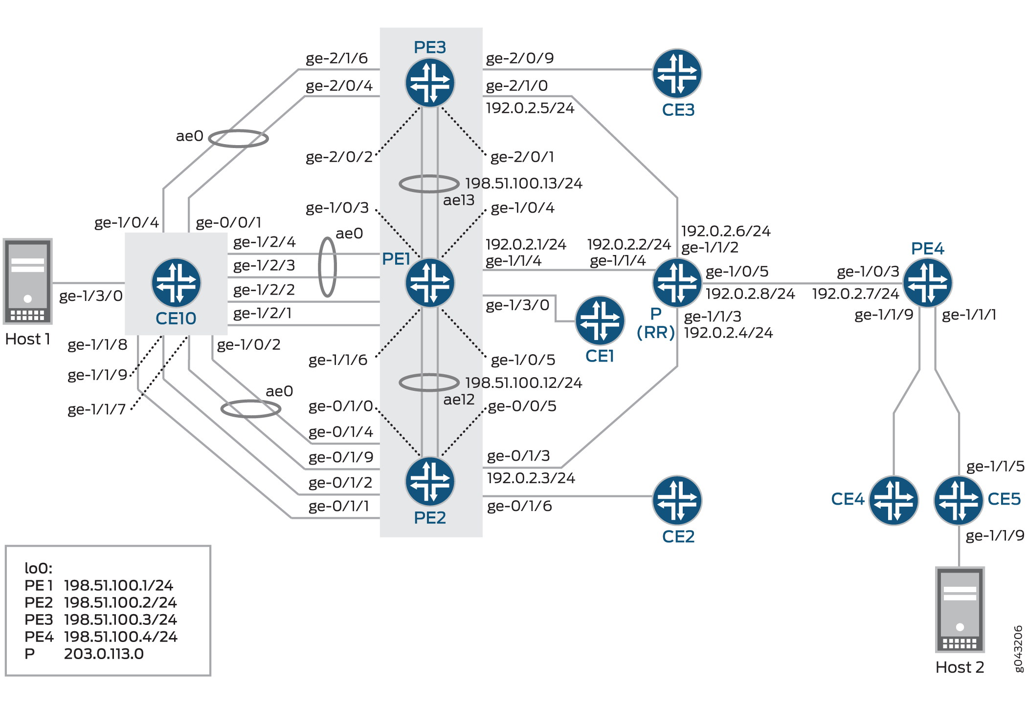
In Figure 1, the core consists of four provider edge (PE) routers and a provider router (P) that is configured as a route reflector (RR). Router CE10 is multihomed to Routers PE1, PE2, and PE3. Each PE router is also connected to a single-homed customer site.
There are three routing instances running in the topology – VS-1, VS-2, and mhevpn, along with the default routing instance. The routing instances share nine VLANs with three ESIs each. The VS-1 and VS-2 routing instances are configured as a virtual switch type of routing instance, and the mhevpn routing instance is an EVPN routing instance.
Three aggregated bundles – ae0, ae1, and ae2 – are used to connect the multihomed CE device, CE10, to Routers PE1, PE2, and PE3. These aggregated bundles are configured for three ESIs each. The aggregated bundles, ae12 and ae13, are used to interconnect Routers PE1 and PE2, and PE1 and PE3, respectively.
For Active-Active redundancy, additional configurations are required in the “interconnect”
stanza to enable DCI interconnection. For a default switch (switch-options)
configuration, be sure to set the DCI under global protocols evpn: [edit
global protocols evpn].
Protocols EVPN Example:
evpn-vxlan-dc1
        vtep-source-interface lo0.0;
        instance-type mac-vrf;
        route-distinguisher 101:1;
        vrf-target target:1:1;
        protocols {
            evpn {
                encapsulation vxlan;
                extended-vni-list all;
        interconnect {
            vrf-target  target:2:2;
            vrf-import
            route-distinguisher 101:2;
            interconnected-vni-list all;
 		    esi {
 		        00:00:01:02:03:04:05:06:07:08;
 			    all-active;
               }
          }
      }
  }
        vlans  {
            bd1 {
                vlan-id 51;
                l3-interface irb.0;
                vxlan {
                    vni 51;
                    translation-vni
                }
            }
        }
    }


global
 protocols {
      evpn {
 	 	interconnect-multihoming-peer-gateways
       }
}Configure this statement interconnect-multihoming-peer-gateways to
contain a list of all DCI peers on the same DC.
The list can contain up to 64 peer gateway entries. Be sure to configure under the
global protocol evpn stanza [edit global protocols evpn] and not under
any mac-vrf setting [edit protocols evpn-vxlan-dc1 instance-type mac-vrf].
Configuration
CLI Quick Configuration
To quickly configure this example, copy the
following commands, paste them into a text file, remove any line breaks,
change any details necessary to match your network configuration,
copy and paste the commands into the CLI at the [edit] hierarchy
level, and then enter commit from configuration mode.
CE10
set chassis aggregated-devices ethernet device-count 20
set chassis network-services enhanced-ip
set interfaces ge-0/0/1 gigether-options 802.3ad ae0
set interfaces ge-1/0/2 gigether-options 802.3ad ae0
set interfaces ge-1/0/4 gigether-options 802.3ad ae0
set interfaces ge-1/1/7 gigether-options 802.3ad ae0
set interfaces ge-1/1/8 gigether-options 802.3ad ae2
set interfaces ge-1/1/9 gigether-options 802.3ad ae1
set interfaces ge-1/2/1 gigether-options 802.3ad ae2
set interfaces ge-1/2/2 gigether-options 802.3ad ae1
set interfaces ge-1/2/3 gigether-options 802.3ad ae0
set interfaces ge-1/2/4 gigether-options 802.3ad ae0
set interfaces ge-1/3/0 flexible-vlan-tagging
set interfaces ge-1/3/0 encapsulation flexible-ethernet-services
set interfaces ge-1/3/0 unit 0 encapsulation vlan-bridge
set interfaces ge-1/3/0 unit 0 vlan-id 10
set interfaces ge-1/3/0 unit 1 encapsulation vlan-bridge
set interfaces ge-1/3/0 unit 1 vlan-id 20
set interfaces ge-1/3/0 unit 2 encapsulation vlan-bridge
set interfaces ge-1/3/0 unit 2 vlan-id 30
set interfaces ge-1/3/0 unit 110 encapsulation vlan-bridge
set interfaces ge-1/3/0 unit 110 vlan-id 110
set interfaces ge-1/3/0 unit 120 encapsulation vlan-bridge
set interfaces ge-1/3/0 unit 120 vlan-id 120
set interfaces ge-1/3/0 unit 130 encapsulation vlan-bridge
set interfaces ge-1/3/0 unit 130 vlan-id 130
set interfaces ge-1/3/0 unit 210 encapsulation vlan-bridge
set interfaces ge-1/3/0 unit 210 vlan-id 210
set interfaces ge-1/3/0 unit 220 encapsulation vlan-bridge
set interfaces ge-1/3/0 unit 220 vlan-id 220
set interfaces ge-1/3/0 unit 230 encapsulation vlan-bridge
set interfaces ge-1/3/0 unit 230 vlan-id 230
set interfaces ae0 flexible-vlan-tagging
set interfaces ae0 encapsulation flexible-ethernet-services
set interfaces ae0 aggregated-ether-options minimum-links 1
set interfaces ae0 unit 0 encapsulation vlan-bridge
set interfaces ae0 unit 0 vlan-id 10
set interfaces ae0 unit 110 encapsulation vlan-bridge
set interfaces ae0 unit 110 vlan-id 110
set interfaces ae0 unit 210 encapsulation vlan-bridge
set interfaces ae0 unit 210 vlan-id 210
set interfaces ae1 flexible-vlan-tagging
set interfaces ae1 encapsulation flexible-ethernet-services
set interfaces ae1 aggregated-ether-options minimum-links 1
set interfaces ae1 unit 1 encapsulation vlan-bridge
set interfaces ae1 unit 1 vlan-id 20
set interfaces ae1 unit 120 encapsulation vlan-bridge
set interfaces ae1 unit 120 vlan-id 120
set interfaces ae1 unit 220 encapsulation vlan-bridge
set interfaces ae1 unit 220 vlan-id 220
set interfaces ae2 flexible-vlan-tagging
set interfaces ae2 encapsulation flexible-ethernet-services
set interfaces ae2 aggregated-ether-options minimum-links 1
set interfaces ae2 unit 2 encapsulation vlan-bridge
set interfaces ae2 unit 2 vlan-id 30
set interfaces ae2 unit 130 encapsulation vlan-bridge
set interfaces ae2 unit 130 vlan-id 130
set interfaces ae2 unit 230 encapsulation vlan-bridge
set interfaces ae2 unit 230 vlan-id 230
set routing-options forwarding-table export load-balancing-policy
set protocols l2-learning global-mac-table-aging-time 18000
set policy-options policy-statement load-balancing-policy then load-balance per-packet
set bridge-domains bd10 domain-type bridge
set bridge-domains bd10 vlan-id 10
set bridge-domains bd10 interface ae0.0
set bridge-domains bd10 interface ge-1/3/0.0
set bridge-domains bd110 domain-type bridge
set bridge-domains bd110 vlan-id 110
set bridge-domains bd110 interface ae0.110
set bridge-domains bd110 interface ge-1/3/0.110
set bridge-domains bd120 domain-type bridge
set bridge-domains bd120 vlan-id 120
set bridge-domains bd120 interface ge-1/3/0.120
set bridge-domains bd120 interface ae1.120
set bridge-domains bd130 domain-type bridge
set bridge-domains bd130 vlan-id 130
set bridge-domains bd130 interface ge-1/3/0.130
set bridge-domains bd130 interface ae2.130
set bridge-domains bd20 domain-type bridge
set bridge-domains bd20 vlan-id 20
set bridge-domains bd20 interface ge-1/3/0.1
set bridge-domains bd20 interface ae1.1
set bridge-domains bd210 domain-type bridge
set bridge-domains bd210 vlan-id 210
set bridge-domains bd210 interface ae0.210
set bridge-domains bd210 interface ge-1/3/0.210
set bridge-domains bd220 domain-type bridge
set bridge-domains bd220 vlan-id 220
set bridge-domains bd220 interface ge-1/3/0.220
set bridge-domains bd220 interface ae1.220
set bridge-domains bd230 domain-type bridge
set bridge-domains bd230 vlan-id 230
set bridge-domains bd230 interface ge-1/3/0.230
set bridge-domains bd230 interface ae2.230
set bridge-domains bd30 domain-type bridge
set bridge-domains bd30 vlan-id 30
set bridge-domains bd30 interface ge-1/3/0.2
set bridge-domains bd30 interface ae2.2
CE5
set chassis aggregated-devices ethernet device-count 20
set chassis network-services enhanced-ip
set interfaces ge-1/1/5 gigether-options 802.3ad ae0
set interfaces ge-1/1/9 flexible-vlan-tagging
set interfaces ge-1/1/9 encapsulation flexible-ethernet-services
set interfaces ge-1/1/9 unit 0 encapsulation vlan-bridge
set interfaces ge-1/1/9 unit 0 vlan-id 10
set interfaces ge-1/1/9 unit 1 encapsulation vlan-bridge
set interfaces ge-1/1/9 unit 1 vlan-id 20
set interfaces ge-1/1/9 unit 2 encapsulation vlan-bridge
set interfaces ge-1/1/9 unit 2 vlan-id 30
set interfaces ge-1/1/9 unit 110 encapsulation vlan-bridge
set interfaces ge-1/1/9 unit 110 vlan-id 110
set interfaces ge-1/1/9 unit 120 encapsulation vlan-bridge
set interfaces ge-1/1/9 unit 120 vlan-id 120
set interfaces ge-1/1/9 unit 130 encapsulation vlan-bridge
set interfaces ge-1/1/9 unit 130 vlan-id 130
set interfaces ge-1/1/9 unit 210 encapsulation vlan-bridge
set interfaces ge-1/1/9 unit 210 vlan-id 210
set interfaces ge-1/1/9 unit 220 encapsulation vlan-bridge
set interfaces ge-1/1/9 unit 220 vlan-id 220
set interfaces ge-1/1/9 unit 230 encapsulation vlan-bridge
set interfaces ge-1/1/9 unit 230 vlan-id 230
set interfaces ae0 flexible-vlan-tagging
set interfaces ae0 encapsulation flexible-ethernet-services
set interfaces ae0 unit 0 encapsulation vlan-bridge
set interfaces ae0 unit 0 vlan-id 10
set interfaces ae0 unit 1 encapsulation vlan-bridge
set interfaces ae0 unit 1 vlan-id 20
set interfaces ae0 unit 2 encapsulation vlan-bridge
set interfaces ae0 unit 2 vlan-id 30
set interfaces ae0 unit 110 encapsulation vlan-bridge
set interfaces ae0 unit 110 vlan-id 110
set interfaces ae0 unit 120 encapsulation vlan-bridge
set interfaces ae0 unit 120 vlan-id 120
set interfaces ae0 unit 130 encapsulation vlan-bridge
set interfaces ae0 unit 130 vlan-id 130
set interfaces ae0 unit 210 encapsulation vlan-bridge
set interfaces ae0 unit 210 vlan-id 210
set interfaces ae0 unit 220 encapsulation vlan-bridge
set interfaces ae0 unit 220 vlan-id 220
set interfaces ae0 unit 230 encapsulation vlan-bridge
set interfaces ae0 unit 230 vlan-id 230
set interfaces lo0 unit 6 family inet address 203.0.113.0/24
set interfaces lo0 unit 6 family iso address 47.0005.80ff.f800.0000.0108.0000.6006.0070.0600
set routing-options forwarding-table export load-balancing-policy
set protocols l2-learning global-mac-table-aging-time 18000
set policy-options policy-statement load-balancing-policy then load-balance per-packet
set bridge-domains bd10 domain-type bridge
set bridge-domains bd10 vlan-id 10
set bridge-domains bd10 interface ae0.0
set bridge-domains bd10 interface ge-1/1/9.0
set bridge-domains bd110 domain-type bridge
set bridge-domains bd110 vlan-id 110
set bridge-domains bd110 interface ae0.110
set bridge-domains bd110 interface ge-1/1/9.110
set bridge-domains bd120 domain-type bridge
set bridge-domains bd120 vlan-id 120
set bridge-domains bd120 interface ge-1/1/9.120
set bridge-domains bd120 interface ae0.120
set bridge-domains bd130 domain-type bridge
set bridge-domains bd130 vlan-id 130
set bridge-domains bd130 interface ge-1/1/9.130
set bridge-domains bd130 interface ae0.130
set bridge-domains bd20 domain-type bridge
set bridge-domains bd20 vlan-id 20
set bridge-domains bd20 interface ae0.1
set bridge-domains bd20 interface ge-1/1/9.1
set bridge-domains bd210 domain-type bridge
set bridge-domains bd210 vlan-id 210
set bridge-domains bd210 interface ae0.210
set bridge-domains bd210 interface ge-1/1/9.210
set bridge-domains bd220 domain-type bridge
set bridge-domains bd220 vlan-id 220
set bridge-domains bd220 interface ge-1/1/9.220
set bridge-domains bd220 interface ae0.220
set bridge-domains bd230 domain-type bridge
set bridge-domains bd230 vlan-id 230
set bridge-domains bd230 interface ge-1/1/9.230
set bridge-domains bd230 interface ae0.230
set bridge-domains bd30 domain-type bridge
set bridge-domains bd30 vlan-id 30
set bridge-domains bd30 interface ge-1/1/9.2
set bridge-domains bd30 interface ae0.2
PE1
set chassis aggregated-devices ethernet device-count 20
set chassis network-services enhanced-ip
set interfaces ge-1/0/3 gigether-options 802.3ad ae13
set interfaces ge-1/0/4 gigether-options 802.3ad ae13
set interfaces ge-1/0/5 gigether-options 802.3ad ae12
set interfaces ge-1/1/4 unit 0 family inet address 192.0.2.1/24
set interfaces ge-1/1/4 unit 0 family iso
set interfaces ge-1/1/4 unit 0 family mpls
set interfaces ge-1/1/6 gigether-options 802.3ad ae12
set interfaces ge-1/2/1 flexible-vlan-tagging
set interfaces ge-1/2/1 encapsulation flexible-ethernet-services
set interfaces ge-1/2/1 esi 00:33:33:33:33:33:33:33:33:33
set interfaces ge-1/2/1 esi all-active
set interfaces ge-1/2/1 unit 0 encapsulation vlan-bridge
set interfaces ge-1/2/1 unit 0 vlan-id 30
set interfaces ge-1/2/1 unit 130 family bridge interface-mode trunk
set interfaces ge-1/2/1 unit 130 family bridge vlan-id-list 130
set interfaces ge-1/2/1 unit 230 family bridge interface-mode trunk
set interfaces ge-1/2/1 unit 230 family bridge vlan-id-list 230
set interfaces ge-1/2/2 flexible-vlan-tagging
set interfaces ge-1/2/2 encapsulation flexible-ethernet-services
set interfaces ge-1/2/2 esi 00:22:22:22:22:22:22:22:22:22
set interfaces ge-1/2/2 esi all-active
set interfaces ge-1/2/2 unit 0 encapsulation vlan-bridge
set interfaces ge-1/2/2 unit 0 vlan-id 20
set interfaces ge-1/2/2 unit 120 family bridge interface-mode trunk
set interfaces ge-1/2/2 unit 120 family bridge vlan-id-list 120
set interfaces ge-1/2/2 unit 220 family bridge interface-mode trunk
set interfaces ge-1/2/2 unit 220 family bridge vlan-id-list 220
set interfaces ge-1/2/3 gigether-options 802.3ad ae0
set interfaces ge-1/2/4 gigether-options 802.3ad ae0
set interfaces ge-1/3/0 flexible-vlan-tagging
set interfaces ge-1/3/0 encapsulation flexible-ethernet-services
set interfaces ge-1/3/0 unit 0 encapsulation vlan-bridge
set interfaces ge-1/3/0 unit 0 vlan-id 10
set interfaces ge-1/3/0 unit 100 family bridge interface-mode trunk
set interfaces ge-1/3/0 unit 100 family bridge vlan-id-list 110
set interfaces ge-1/3/0 unit 100 family bridge vlan-id-list 120
set interfaces ge-1/3/0 unit 100 family bridge vlan-id-list 130
set interfaces ge-1/3/0 unit 200 family bridge interface-mode trunk
set interfaces ge-1/3/0 unit 200 family bridge vlan-id-list 210
set interfaces ge-1/3/0 unit 200 family bridge vlan-id-list 220
set interfaces ge-1/3/0 unit 200 family bridge vlan-id-list 230
set interfaces ae0 flexible-vlan-tagging
set interfaces ae0 encapsulation flexible-ethernet-services
set interfaces ae0 esi 00:11:11:11:11:11:11:11:11:11
set interfaces ae0 esi all-active
set interfaces ae0 unit 0 encapsulation vlan-bridge
set interfaces ae0 unit 0 vlan-id 10
set interfaces ae0 unit 110 family bridge interface-mode trunk
set interfaces ae0 unit 110 family bridge vlan-id-list 110
set interfaces ae0 unit 210 family bridge interface-mode trunk
set interfaces ae0 unit 210 family bridge vlan-id-list 210
set interfaces ae12 flexible-vlan-tagging
set interfaces ae12 encapsulation flexible-ethernet-services
set interfaces ae12 aggregated-ether-options minimum-links 1
set interfaces ae12 unit 0 vlan-id 1200
set interfaces ae12 unit 0 family inet address 198.51.100.12/24
set interfaces ae12 unit 0 family iso
set interfaces ae12 unit 0 family mpls
set interfaces ae13 flexible-vlan-tagging
set interfaces ae13 encapsulation flexible-ethernet-services
set interfaces ae13 aggregated-ether-options minimum-links 1
set interfaces ae13 unit 0 vlan-tags outer 1300
set interfaces ae13 unit 0 vlan-tags inner 13
set interfaces ae13 unit 0 family inet address 198.51.100.13/24
set interfaces ae13 unit 0 family iso
set interfaces ae13 unit 0 family mpls
set interfaces irb unit 0 family inet address 192.0.2.9/24
set interfaces irb unit 0 mac 00:99:99:99:01:99
set interfaces irb unit 1 family inet address 192.0.2.10/24
set interfaces irb unit 1 mac 00:99:99:99:02:99
set interfaces irb unit 2 family inet address 192.0.2.11/24
set interfaces irb unit 2 mac 00:99:99:99:03:99
set interfaces irb unit 10 family inet address 192.0.2.12/24
set interfaces irb unit 10 mac 00:99:99:99:01:90
set interfaces lo0 unit 0 family inet address 198.51.100.1/24 primary
set interfaces lo0 unit 0 family iso
set routing-options router-id 198.51.100.1
set routing-options autonomous-system 65221
set routing-options forwarding-table export load-balancing-policy
set protocols rsvp interface all
set protocols rsvp interface fxp0.0 disable
set protocols mpls label-switched-path pe1tope2 from 198.51.100.1
set protocols mpls label-switched-path pe1tope2 to 198.51.100.2
set protocols mpls label-switched-path pe1tope2 primary direct_to_pe2
set protocols mpls label-switched-path pe1tope3 from 198.51.100.1
set protocols mpls label-switched-path pe1tope3 to 198.51.100.3
set protocols mpls label-switched-path pe1tope3 primary direct_to_pe3
set protocols mpls label-switched-path pe1tope4 from 198.51.100.1
set protocols mpls label-switched-path pe1tope4 to 198.51.100.4
set protocols mpls label-switched-path pe1tope4 primary direct_to_pe4
set protocols mpls path pe4_to_pe3 198.51.100.4 strict
set protocols mpls path pe4_to_pe3 198.51.100.3 strict
set protocols mpls path direct_to_pe2 198.51.100.5 strict
set protocols mpls path direct_to_pe3 198.51.100.6 strict
set protocols mpls path direct_to_pe4 198.51.100.9 strict
set protocols mpls path pe2_to_pe3 198.51.100.2 strict
set protocols mpls path pe2_to_pe3 198.51.100.3 strict
set protocols mpls interface all
set protocols mpls interface fxp0.0 disable
set protocols bgp group RR type internal
set protocols bgp group RR local-address 198.51.100.1
set protocols bgp group RR family evpn signaling
set protocols bgp group RR neighbor 203.0.113.0
set protocols isis level 1 disable
set protocols isis interface all level 2 metric 10
set protocols isis interface fxp0.0 disable
set protocols isis interface lo0.0 level 2 metric 0
set protocols ldp deaggregate
set protocols ldp interface all
set protocols ldp interface fxp0.0 disable
set protocols evpn
set protocols l2-learning global-mac-table-aging-time 18000
set policy-options policy-statement load-balancing-policy then load-balance per-packet
set routing-instances VS-1 instance-type virtual-switch
set routing-instances VS-1 interface ge-1/2/1.130
set routing-instances VS-1 interface ge-1/2/2.120
set routing-instances VS-1 interface ge-1/3/0.100
set routing-instances VS-1 interface ae0.110
set routing-instances VS-1 route-distinguisher 198.51.100.1:101
set routing-instances VS-1 vrf-target target:100:101
set routing-instances VS-1 protocols evpn extended-vlan-list 110
set routing-instances VS-1 protocols evpn extended-vlan-list 120
set routing-instances VS-1 protocols evpn extended-vlan-list 130
set routing-instances VS-1 protocols evpn default-gateway do-not-advertise
set routing-instances VS-1 bridge-domains bd-110 vlan-id 110
set routing-instances VS-1 bridge-domains bd-110 routing-interface irb.0
set routing-instances VS-1 bridge-domains bd-120 vlan-id 120
set routing-instances VS-1 bridge-domains bd-120 routing-interface irb.1
set routing-instances VS-1 bridge-domains bd-130 vlan-id 130
set routing-instances VS-1 bridge-domains bd-130 routing-interface irb.2
set routing-instances VS-2 instance-type virtual-switch
set routing-instances VS-2 interface ge-1/2/1.230
set routing-instances VS-2 interface ge-1/2/2.220
set routing-instances VS-2 interface ge-1/3/0.200
set routing-instances VS-2 interface ae0.210
set routing-instances VS-2 route-distinguisher 198.51.100.1:201
set routing-instances VS-2 vrf-target target:100:201
set routing-instances VS-2 protocols evpn extended-vlan-list 210
set routing-instances VS-2 protocols evpn extended-vlan-list 220
set routing-instances VS-2 protocols evpn extended-vlan-list 230
set routing-instances VS-2 bridge-domains bd-a vlan-id-list 210
set routing-instances VS-2 bridge-domains bd-a vlan-id-list 220
set routing-instances VS-2 bridge-domains bd-a vlan-id-list 230
set routing-instances mhevpn instance-type evpn
set routing-instances mhevpn vlan-id 10
set routing-instances mhevpn interface ge-1/2/1.0
set routing-instances mhevpn interface ge-1/2/2.0
set routing-instances mhevpn interface ge-1/3/0.0
set routing-instances mhevpn interface ae0.0
set routing-instances mhevpn routing-interface irb.10
set routing-instances mhevpn route-distinguisher 198.51.100.1:1
set routing-instances mhevpn vrf-target target:100:1
set routing-instances mhevpn protocols evpn default-gateway do-not-advertise
set routing-instances vrf instance-type vrf
set routing-instances vrf interface irb.0
set routing-instances vrf interface irb.1
set routing-instances vrf interface irb.2
set routing-instances vrf interface irb.10
set routing-instances vrf route-distinguisher 198.51.100.1:11
set routing-instances vrf vrf-target target:100:11
set routing-instances vrf vrf-table-label
PE2
set chassis aggregated-devices ethernet device-count 20
set chassis network-services enhanced-ip
set interfaces ge-0/0/5 gigether-options 802.3ad ae12
set interfaces ge-0/1/0 gigether-options 802.3ad ae12
set interfaces ge-0/1/1 flexible-vlan-tagging
set interfaces ge-0/1/1 encapsulation flexible-ethernet-services
set interfaces ge-0/1/1 esi 00:33:33:33:33:33:33:33:33:33
set interfaces ge-0/1/1 esi all-active
set interfaces ge-0/1/1 unit 0 encapsulation vlan-bridge
set interfaces ge-0/1/1 unit 0 vlan-id 30
set interfaces ge-0/1/1 unit 130 family bridge interface-mode trunk
set interfaces ge-0/1/1 unit 130 family bridge vlan-id-list 130
set interfaces ge-0/1/1 unit 230 family bridge interface-mode trunk
set interfaces ge-0/1/1 unit 230 family bridge vlan-id-list 230
set interfaces ge-0/1/2 flexible-vlan-tagging
set interfaces ge-0/1/2 encapsulation flexible-ethernet-services
set interfaces ge-0/1/2 esi 00:22:22:22:22:22:22:22:22:22
set interfaces ge-0/1/2 esi all-active
set interfaces ge-0/1/2 unit 0 encapsulation vlan-bridge
set interfaces ge-0/1/2 unit 0 vlan-id 20
set interfaces ge-0/1/2 unit 120 family bridge interface-mode trunk
set interfaces ge-0/1/2 unit 120 family bridge vlan-id-list 120
set interfaces ge-0/1/2 unit 220 family bridge interface-mode trunk
set interfaces ge-0/1/2 unit 220 family bridge vlan-id-list 220
set interfaces ge-0/1/3 unit 0 family inet address 192.0.2.3/24
set interfaces ge-0/1/3 unit 0 family iso
set interfaces ge-0/1/3 unit 0 family mpls
set interfaces ge-0/1/4 gigether-options 802.3ad ae0
set interfaces ge-0/1/6 flexible-vlan-tagging
set interfaces ge-0/1/6 encapsulation flexible-ethernet-services
set interfaces ge-0/1/6 unit 0 encapsulation vlan-bridge
set interfaces ge-0/1/6 unit 0 vlan-id 10
set interfaces ge-0/1/6 unit 100 family bridge interface-mode trunk
set interfaces ge-0/1/6 unit 100 family bridge vlan-id-list 110
set interfaces ge-0/1/6 unit 100 family bridge vlan-id-list 120
set interfaces ge-0/1/6 unit 100 family bridge vlan-id-list 130
set interfaces ge-0/1/6 unit 200 family bridge interface-mode trunk
set interfaces ge-0/1/6 unit 200 family bridge vlan-id-list 210
set interfaces ge-0/1/6 unit 200 family bridge vlan-id-list 220
set interfaces ge-0/1/6 unit 200 family bridge vlan-id-list 230
set interfaces ge-0/1/9 gigether-options 802.3ad ae0
set interfaces ae0 flexible-vlan-tagging
set interfaces ae0 encapsulation flexible-ethernet-services
set interfaces ae0 esi 00:11:11:11:11:11:11:11:11:11
set interfaces ae0 esi all-active
set interfaces ae0 unit 0 encapsulation vlan-bridge
set interfaces ae0 unit 0 vlan-id 10
set interfaces ae0 unit 110 family bridge interface-mode trunk
set interfaces ae0 unit 110 family bridge vlan-id-list 110
set interfaces ae0 unit 210 family bridge interface-mode trunk
set interfaces ae0 unit 210 family bridge vlan-id-list 210
set interfaces ae12 flexible-vlan-tagging
set interfaces ae12 encapsulation flexible-ethernet-services
set interfaces ae12 aggregated-ether-options minimum-links 1
set interfaces ae12 unit 0 vlan-id 1200
set interfaces ae12 unit 0 family inet address 198.51.100.5/24
set interfaces ae12 unit 0 family iso
set interfaces ae12 unit 0 family mpls
set interfaces irb unit 0 family inet address 192.0.2.9/24
set interfaces irb unit 0 mac 00:99:99:99:01:99
set interfaces irb unit 1 family inet address 192.0.2.10/24
set interfaces irb unit 1 mac 00:99:99:99:02:99
set interfaces irb unit 2 family inet address 192.0.2.11/24
set interfaces irb unit 2 mac 00:99:99:99:03:99
set interfaces irb unit 10 family inet address 192.0.2.12/24
set interfaces irb unit 10 mac 00:99:99:99:01:90
set interfaces lo0 unit 0 family inet address 198.51.100.2/32 primary
set interfaces lo0 unit 0 family iso
set routing-options router-id 198.51.100.2
set routing-options autonomous-system 65221
set routing-options forwarding-table export load-balancing-policy
set protocols rsvp interface all
set protocols rsvp interface fxp0.0 disable
set protocols mpls label-switched-path pe2tope1 from 198.51.100.2
set protocols mpls label-switched-path pe2tope1 to 198.51.100.1
set protocols mpls label-switched-path pe2tope1 primary direct_to_pe1
set protocols mpls label-switched-path pe2tope3 from 198.51.100.2
set protocols mpls label-switched-path pe2tope3 to 198.51.100.3
set protocols mpls label-switched-path pe2tope3 primary direct_to_pe3
set protocols mpls label-switched-path pe2tope4 from 198.51.100.2
set protocols mpls label-switched-path pe2tope4 to 198.51.100.4
set protocols mpls label-switched-path pe2tope4 primary direct_to_pe4
set protocols mpls path direct_to_pe1 198.51.100.12 strict
set protocols mpls path direct_to_pe3 198.51.100.7 strict
set protocols mpls path direct_to_pe4 198.51.100.8 strict
set protocols mpls interface all
set protocols mpls interface fxp0.0 disable
set protocols bgp group RR type internal
set protocols bgp group RR local-address 198.51.100.2
set protocols bgp group RR family evpn signaling
set protocols bgp group RR neighbor 203.0.113.0
set protocols isis level 1 disable
set protocols isis interface all level 2 metric 10
set protocols isis interface fxp0.0 disable
set protocols isis interface lo0.0 level 2 metric 0
set protocols ldp deaggregate
set protocols ldp interface all
set protocols ldp interface fxp0.0 disable
set protocols l2-learning global-mac-table-aging-time 18000
set policy-options policy-statement load-balancing-policy then load-balance per-packet
set routing-instances VS-1 instance-type virtual-switch
set routing-instances VS-1 interface ge-0/1/1.130
set routing-instances VS-1 interface ge-0/1/2.120
set routing-instances VS-1 interface ge-0/1/6.100
set routing-instances VS-1 interface ae0.110
set routing-instances VS-1 route-distinguisher 198.51.100.2:101
set routing-instances VS-1 vrf-target target:100:101
set routing-instances VS-1 protocols evpn extended-vlan-list 110
set routing-instances VS-1 protocols evpn extended-vlan-list 120
set routing-instances VS-1 protocols evpn extended-vlan-list 130
set routing-instances VS-1 protocols evpn default-gateway do-not-advertise
set routing-instances VS-1 bridge-domains bd-110 vlan-id 110
set routing-instances VS-1 bridge-domains bd-110 routing-interface irb.0
set routing-instances VS-1 bridge-domains bd-120 vlan-id 120
set routing-instances VS-1 bridge-domains bd-120 routing-interface irb.1
set routing-instances VS-1 bridge-domains bd-130 vlan-id 130
set routing-instances VS-1 bridge-domains bd-130 routing-interface irb.2
set routing-instances VS-2 instance-type virtual-switch
set routing-instances VS-2 interface ge-0/1/1.230
set routing-instances VS-2 interface ge-0/1/2.220
set routing-instances VS-2 interface ge-0/1/6.200
set routing-instances VS-2 interface ae0.210
set routing-instances VS-2 route-distinguisher 198.51.100.2:201
set routing-instances VS-2 vrf-target target:100:201
set routing-instances VS-2 protocols evpn extended-vlan-list 210
set routing-instances VS-2 protocols evpn extended-vlan-list 220
set routing-instances VS-2 protocols evpn extended-vlan-list 230
set routing-instances VS-2 bridge-domains bd-a vlan-id-list 210
set routing-instances VS-2 bridge-domains bd-a vlan-id-list 220
set routing-instances VS-2 bridge-domains bd-a vlan-id-list 230
set routing-instances mhevpn instance-type evpn
set routing-instances mhevpn vlan-id 10
set routing-instances mhevpn interface ge-0/1/1.0
set routing-instances mhevpn interface ge-0/1/2.0
set routing-instances mhevpn interface ge-0/1/6.0
set routing-instances mhevpn interface ae0.0
set routing-instances mhevpn routing-interface irb.10
set routing-instances mhevpn route-distinguisher 198.51.100.2:1
set routing-instances mhevpn vrf-target target:100:1
set routing-instances mhevpn protocols evpn default-gateway do-not-advertise
set routing-instances vrf instance-type vrf
set routing-instances vrf interface irb.0
set routing-instances vrf interface irb.1
set routing-instances vrf interface irb.2
set routing-instances vrf interface irb.10
set routing-instances vrf route-distinguisher 198.51.100.2:11
set routing-instances vrf vrf-target target:100:11
set routing-instances vrf vrf-table-label
PE3
set chassis aggregated-devices ethernet device-count 20
set chassis network-services enhanced-ip
set interfaces ge-2/0/1 gigether-options 802.3ad ae13
set interfaces ge-2/0/2 gigether-options 802.3ad ae13
set interfaces ge-2/0/4 gigether-options 802.3ad ae0
set interfaces ge-2/0/9 flexible-vlan-tagging
set interfaces ge-2/0/9 encapsulation flexible-ethernet-services
set interfaces ge-2/0/9 unit 0 encapsulation vlan-bridge
set interfaces ge-2/0/9 unit 0 vlan-id 10
set interfaces ge-2/0/9 unit 100 family bridge interface-mode trunk
set interfaces ge-2/0/9 unit 100 family bridge vlan-id-list 110
set interfaces ge-2/0/9 unit 100 family bridge vlan-id-list 120
set interfaces ge-2/0/9 unit 100 family bridge vlan-id-list 130
set interfaces ge-2/0/9 unit 200 family bridge interface-mode trunk
set interfaces ge-2/0/9 unit 200 family bridge vlan-id-list 210
set interfaces ge-2/0/9 unit 200 family bridge vlan-id-list 220
set interfaces ge-2/0/9 unit 200 family bridge vlan-id-list 230
set interfaces ge-2/1/0 unit 0 family inet address 192.0.2.5/24
set interfaces ge-2/1/0 unit 0 family iso
set interfaces ge-2/1/0 unit 0 family mpls
set interfaces ge-2/1/6 gigether-options 802.3ad ae0
set interfaces ae0 flexible-vlan-tagging
set interfaces ae0 encapsulation flexible-ethernet-services
set interfaces ae0 esi 00:11:11:11:11:11:11:11:11:11
set interfaces ae0 esi all-active
set interfaces ae0 unit 0 encapsulation vlan-bridge
set interfaces ae0 unit 0 vlan-id 10
set interfaces ae0 unit 110 family bridge interface-mode trunk
set interfaces ae0 unit 110 family bridge vlan-id-list 110
set interfaces ae0 unit 210 family bridge interface-mode trunk
set interfaces ae0 unit 210 family bridge vlan-id-list 210
set interfaces ae13 flexible-vlan-tagging
set interfaces ae13 encapsulation flexible-ethernet-services
set interfaces ae13 aggregated-ether-options minimum-links 1
set interfaces ae13 unit 0 vlan-tags outer 1300
set interfaces ae13 unit 0 vlan-tags inner 13
set interfaces ae13 unit 0 family inet address 198.51.100.6/24
set interfaces ae13 unit 0 family iso
set interfaces ae13 unit 0 family mpls
set interfaces irb unit 0 family inet address 192.0.2.9/24
set interfaces irb unit 0 mac 00:99:99:99:01:99
set interfaces irb unit 1 family inet address 192.0.2.10/24
set interfaces irb unit 1 mac 00:99:99:99:02:99
set interfaces irb unit 2 family inet address 192.0.2.11/24
set interfaces irb unit 2 mac 00:99:99:99:03:99
set interfaces irb unit 10 family inet address 192.0.2.12/24
set interfaces irb unit 10 mac 00:99:99:99:01:90
set interfaces lo0 unit 0 family inet address 198.51.100.3/32 primary
set interfaces lo0 unit 0 family iso
set routing-options router-id 198.51.100.3
set routing-options autonomous-system 65221
set routing-options forwarding-table export load-balancing-policy
set protocols rsvp interface all
set protocols rsvp interface fxp0.0 disable
set protocols mpls label-switched-path pe3tope1 from 198.51.100.3
set protocols mpls label-switched-path pe3tope1 to 198.51.100.1
set protocols mpls label-switched-path pe3tope1 primary direct_to_pe1
set protocols mpls label-switched-path pe3tope2 from 198.51.100.3
set protocols mpls label-switched-path pe3tope2 to 198.51.100.2
set protocols mpls label-switched-path pe3tope2 primary direct_to_pe2
set protocols mpls label-switched-path pe3tope4 from 198.51.100.3
set protocols mpls label-switched-path pe3tope4 to 198.51.100.4
set protocols mpls label-switched-path pe3tope4 primary direct_to_pe4
set protocols mpls path direct_to_pe1 198.51.100.13 strict
set protocols mpls path direct_to_pe2 198.51.100.10 strict
set protocols mpls path direct_to_pe4 198.51.100.11 strict
set protocols mpls interface all
set protocols mpls interface fxp0.0 disable
set protocols bgp group RR type internal
set protocols bgp group RR local-address 198.51.100.3
set protocols bgp group RR family evpn signaling
set protocols bgp group RR neighbor 203.0.113.0
set protocols isis level 1 disable
set protocols isis interface all level 2 metric 10
set protocols isis interface fxp0.0 disable
set protocols isis interface lo0.0 level 2 metric 0
set protocols ldp deaggregate
set protocols ldp interface all
set protocols ldp interface fxp0.0 disable
set protocols l2-learning global-mac-table-aging-time 18000
set policy-options policy-statement load-balancing-policy then load-balance per-packet
set routing-instances VS-1 instance-type virtual-switch
set routing-instances VS-1 interface ge-2/0/9.100
set routing-instances VS-1 interface ae0.110
set routing-instances VS-1 route-distinguisher 198.51.100.3:101
set routing-instances VS-1 vrf-target target:100:101
set routing-instances VS-1 protocols evpn extended-vlan-list 110
set routing-instances VS-1 protocols evpn extended-vlan-list 120
set routing-instances VS-1 protocols evpn extended-vlan-list 130
set routing-instances VS-1 protocols evpn default-gateway do-not-advertise
set routing-instances VS-1 bridge-domains bd-110 vlan-id 110
set routing-instances VS-1 bridge-domains bd-110 routing-interface irb.0
set routing-instances VS-1 bridge-domains bd-120 vlan-id 120
set routing-instances VS-1 bridge-domains bd-120 routing-interface irb.1
set routing-instances VS-1 bridge-domains bd-130 vlan-id 130
set routing-instances VS-1 bridge-domains bd-130 routing-interface irb.2
set routing-instances VS-2 instance-type virtual-switch
set routing-instances VS-2 interface ge-2/0/9.200
set routing-instances VS-2 interface ae0.210
set routing-instances VS-2 route-distinguisher 198.51.100.3:201
set routing-instances VS-2 vrf-target target:100:201
set routing-instances VS-2 protocols evpn extended-vlan-list 210
set routing-instances VS-2 protocols evpn extended-vlan-list 220
set routing-instances VS-2 protocols evpn extended-vlan-list 230
set routing-instances VS-2 bridge-domains bd-a vlan-id-list 210
set routing-instances VS-2 bridge-domains bd-a vlan-id-list 220
set routing-instances VS-2 bridge-domains bd-a vlan-id-list 230
set routing-instances mhevpn instance-type evpn
set routing-instances mhevpn vlan-id 10
set routing-instances mhevpn interface ge-2/0/9.0
set routing-instances mhevpn interface ae0.0
set routing-instances mhevpn routing-interface irb.10
set routing-instances mhevpn route-distinguisher 198.51.100.3:1
set routing-instances mhevpn vrf-target target:100:1
set routing-instances mhevpn protocols evpn default-gateway do-not-advertise
set routing-instances vrf instance-type vrf
set routing-instances vrf interface irb.0
set routing-instances vrf interface irb.1
set routing-instances vrf interface irb.2
set routing-instances vrf interface irb.10
set routing-instances vrf route-distinguisher 198.51.100.3:11
set routing-instances vrf vrf-target target:100:11
set routing-instances vrf vrf-table-label
PE4
set chassis aggregated-devices ethernet device-count 20
set chassis network-services enhanced-ip
set interfaces ge-1/0/3 unit 0 family inet address 192.0.2.7/24
set interfaces ge-1/0/3 unit 0 family iso
set interfaces ge-1/0/3 unit 0 family mpls
set interfaces ge-1/1/1 flexible-vlan-tagging
set interfaces ge-1/1/1 encapsulation flexible-ethernet-services
set interfaces ge-1/1/1 esi 00:44:44:44:44:44:44:44:44:44
set interfaces ge-1/1/1 esi all-active
set interfaces ge-1/1/1 unit 0 encapsulation vlan-bridge
set interfaces ge-1/1/1 unit 0 vlan-id 10
set interfaces ge-1/1/1 unit 100 family bridge interface-mode trunk
set interfaces ge-1/1/1 unit 100 family bridge vlan-id-list 110
set interfaces ge-1/1/1 unit 100 family bridge vlan-id-list 120
set interfaces ge-1/1/1 unit 100 family bridge vlan-id-list 130
set interfaces ge-1/1/1 unit 200 family bridge interface-mode trunk
set interfaces ge-1/1/1 unit 200 family bridge vlan-id-list 210
set interfaces ge-1/1/1 unit 200 family bridge vlan-id-list 220
set interfaces ge-1/1/1 unit 200 family bridge vlan-id-list 230
set interfaces ge-1/1/9 flexible-vlan-tagging
set interfaces ge-1/1/9 encapsulation flexible-ethernet-services
set interfaces ge-1/1/9 unit 0 encapsulation vlan-bridge
set interfaces ge-1/1/9 unit 0 vlan-id 10
set interfaces ge-1/1/9 unit 100 family bridge interface-mode trunk
set interfaces ge-1/1/9 unit 100 family bridge vlan-id-list 110
set interfaces ge-1/1/9 unit 100 family bridge vlan-id-list 120
set interfaces ge-1/1/9 unit 100 family bridge vlan-id-list 130
set interfaces ge-1/1/9 unit 200 family bridge interface-mode trunk
set interfaces ge-1/1/9 unit 200 family bridge vlan-id-list 210
set interfaces ge-1/1/9 unit 200 family bridge vlan-id-list 220
set interfaces ge-1/1/9 unit 200 family bridge vlan-id-list 230
set interfaces irb unit 0 family inet address 192.0.2.9/24
set interfaces irb unit 0 mac 00:99:99:99:01:99
set interfaces irb unit 1 family inet address 192.0.2.10/24
set interfaces irb unit 1 mac 00:99:99:99:02:99
set interfaces irb unit 2 family inet address 192.0.2.11/24
set interfaces irb unit 2 mac 00:99:99:99:03:99
set interfaces irb unit 10 family inet address 192.0.2.12/24
set interfaces irb unit 10 mac 00:99:99:99:01:90
set interfaces lo0 unit 0 family inet address 198.51.100.4/32 primary
set routing-options router-id 198.51.100.4
set routing-options autonomous-system 65221
set routing-options forwarding-table export load-balancing-policy
set protocols rsvp interface all
set protocols rsvp interface fxp0.0 disable
set protocols mpls label-switched-path pe4tope1 from 198.51.100.4
set protocols mpls label-switched-path pe4tope1 to 198.51.100.1
set protocols mpls label-switched-path pe4tope1 primary direct_to_pe1
set protocols mpls label-switched-path pe4tope2 from 198.51.100.4
set protocols mpls label-switched-path pe4tope2 to 198.51.100.2
set protocols mpls label-switched-path pe4tope2 primary direct_to_pe2
set protocols mpls label-switched-path pe4tope3 from 198.51.100.4
set protocols mpls label-switched-path pe4tope3 to 198.51.100.3
set protocols mpls label-switched-path pe4tope3 primary direct_to_pe3
set protocols mpls path pe2_to_pe3 198.51.100.2 strict
set protocols mpls path pe2_to_pe3 198.51.100.3 strict
set protocols mpls path direct_to_pe1 198.51.100.14 strict
set protocols mpls path direct_to_pe2 198.51.100.15 strict
set protocols mpls path direct_to_pe3 198.51.100.16 strict
set protocols mpls interface all
set protocols mpls interface fxp0.0 disable
set protocols bgp group RR type internal
set protocols bgp group RR local-address 198.51.100.4
set protocols bgp group RR family evpn signaling
set protocols bgp group RR neighbor 203.0.113.0
set protocols isis level 1 disable
set protocols isis interface all level 2 metric 10
set protocols isis interface fxp0.0 disable
set protocols isis interface lo0.0 level 2 metric 0
set protocols ldp deaggregate
set protocols ldp interface all
set protocols ldp interface fxp0.0 disable
set protocols l2-learning global-mac-table-aging-time 18000
set policy-options policy-statement load-balancing-policy then load-balance per-packet
set routing-instances VS-1 instance-type virtual-switch
set routing-instances VS-1 interface ge-1/1/1.100
set routing-instances VS-1 interface ge-1/1/9.100
set routing-instances VS-1 route-distinguisher 198.51.100.4:101
set routing-instances VS-1 vrf-target target:100:101
set routing-instances VS-1 protocols evpn extended-vlan-list 110
set routing-instances VS-1 protocols evpn extended-vlan-list 120
set routing-instances VS-1 protocols evpn extended-vlan-list 130
set routing-instances VS-1 protocols evpn default-gateway do-not-advertise
set routing-instances VS-1 bridge-domains bd-110 vlan-id 110
set routing-instances VS-1 bridge-domains bd-110 routing-interface irb.0
set routing-instances VS-1 bridge-domains bd-120 vlan-id 120
set routing-instances VS-1 bridge-domains bd-120 routing-interface irb.1
set routing-instances VS-1 bridge-domains bd-130 vlan-id 130
set routing-instances VS-1 bridge-domains bd-130 routing-interface irb.2
set routing-instances VS-2 instance-type virtual-switch
set routing-instances VS-2 interface ge-1/1/1.200
set routing-instances VS-2 interface ge-1/1/9.200
set routing-instances VS-2 route-distinguisher 198.51.100.4:201
set routing-instances VS-2 vrf-target target:100:201
set routing-instances VS-2 protocols evpn extended-vlan-list 210
set routing-instances VS-2 protocols evpn extended-vlan-list 220
set routing-instances VS-2 protocols evpn extended-vlan-list 230
set routing-instances VS-2 bridge-domains bd-a vlan-id-list 210
set routing-instances VS-2 bridge-domains bd-a vlan-id-list 220
set routing-instances VS-2 bridge-domains bd-a vlan-id-list 230
set routing-instances mhevpn instance-type evpn
set routing-instances mhevpn vlan-id 10
set routing-instances mhevpn interface ge-1/1/1.0
set routing-instances mhevpn interface ge-1/1/9.0
set routing-instances mhevpn routing-interface irb.10
set routing-instances mhevpn route-distinguisher 198.51.100.4:1
set routing-instances mhevpn vrf-target target:100:1
set routing-instances mhevpn protocols evpn default-gateway do-not-advertise
set routing-instances vrf instance-type vrf
set routing-instances vrf interface irb.0
set routing-instances vrf interface irb.1
set routing-instances vrf interface irb.2
set routing-instances vrf interface irb.10
set routing-instances vrf route-distinguisher 198.51.100.4:11
set routing-instances vrf vrf-target target:100:11
set routing-instances vrf vrf-table-label
P (RR)
set interfaces ge-1/0/5 unit 0 family inet address 192.0.2.8/24
set interfaces ge-1/1/2 unit 0 family inet address 192.0.2.6/24
set interfaces ge-1/1/3 unit 0 family inet address 192.0.2.4/24
set interfaces ge-1/1/4 unit 0 family inet address 192.0.2.2/24
set interfaces lo0 unit 0 family inet address 203.0.113.0
set protocols bgp group RR type internal
set protocols bgp group RR local-address 203.0.113.0
set protocols bgp group RR family evpn signaling
set protocols bgp group RR cluster 1.2.3.4
set protocols bgp group RR neighbor 198.51.100.1
set protocols bgp group RR neighbor 198.51.100.2
set protocols bgp group RR neighbor 198.51.100.3
set protocols bgp group RR neighbor 198.51.100.4
set protocols isis interface all level 1 disable
set protocols ldp interface all
set routing-options router-id 203.0.113.0
set routing-options autonomous-system 65221
Procedure
Step-by-Step Procedure
The following example requires you to navigate various levels in the configuration hierarchy. For information about navigating the CLI, see Using the CLI Editor in Configuration Mode.
To configure Router PE1:
Repeat this procedure for all other multihomed PE routers after modifying the appropriate interface names, addresses, and other parameters.
-
Configure the MX Series router to operate in the enhanced-ip mode because the EVPN active-active functionality is supported on routers with MPCs and MIC interfaces only.
A system reboot is required on committing this configuration.
[edit chassis]
user@PE1# set network-services enhanced-ip
-
Specify the number of aggregated Ethernet interfaces to be created.
[edit chassis]
user@PE1# set aggregated-devices ethernet device-count 20
-
Configure Router PE1 interfaces within the ae0 aggregated bundle toward the multihomed customer site, Router CE10.
-
Assign interfaces ge-1/2/3 and ge-1/2/4 within the ae0 aggregated bundle.
[edit interfaces]
user@PE1# set ge-1/2/3 gigether-options 802.3ad ae0
user@PE1# set ge-1/2/4 gigether-options 802.3ad ae0
-
Configure the ae0 aggregated bundle parameters for VLAN tagging and encapsulation.
[edit interfaces]
user@PE1# set ae0 flexible-vlan-tagging
user@PE1# set ae0 encapsulation flexible-ethernet-services
-
Assign an ESI value for the first Ethernet segment and enable EVPN active-active multihoming for the ae0 aggregated bundle.
[edit interfaces]
user@PE1# set ae0 esi 00:11:11:11:11:11:11:11:11:11
user@PE1# set ae0 esi all-active
-
Configure a trunk interface on the bridge network for the ae0 aggregated bundle.
[edit interfaces]
user@PE1# set ae0 unit 0 encapsulation vlan-bridge
user@PE1# set ae0 unit 0 vlan-id 10
user@PE1# set ae0 unit 110 family bridge interface-mode trunk
user@PE1# set ae0 unit 110 family bridge vlan-id-list 110
user@PE1# set ae0 unit 210 family bridge interface-mode trunk
user@PE1# set ae0 unit 210 family bridge vlan-id-list 210
-
-
Configure the other Router PE1 interfaces toward the multihomed customer site, Router CE10.
-
Configure the VLAN tagging and encapsulation parameters for the ge-1/2/2 PE1 interface.
[edit interfaces]
user@PE1# set ge-1/2/2 flexible-vlan-tagging
user@PE1# set ge-1/2/2 encapsulation flexible-ethernet-services
-
Assign an ESI value for the second Ethernet segment and enable EVPN active-active multihoming for the ge-1/2/2 PE1 interface.
[edit interfaces]
user@PE1# set ge-1/2/2 esi 00:22:22:22:22:22:22:22:22:22
user@PE1# set ge-1/2/2 esi all-active
-
Configure a trunk interface on the bridge network for the ge-1/2/2 PE1 interface.
[edit interfaces]
user@PE1# set ge-1/2/2 unit 0 encapsulation vlan-bridge
user@PE1# set ge-1/2/2 unit 0 vlan-id 20
user@PE1# set ge-1/2/2 unit 120 family bridge interface-mode trunk
user@PE1#  set ge-1/2/2 unit 120 family bridge vlan-id-list 120
user@PE1# set ge-1/2/2 unit 220 family bridge interface-mode trunk
user@PE1# set ge-1/2/2 unit 220 family bridge vlan-id-list 220
-
Configure the VLAN tagging and encapsulation parameters for the ge-1/2/1 PE1 interface.
[edit interfaces]
user@PE1# set ge-1/2/1 flexible-vlan-tagging
user@PE1# set ge-1/2/1 encapsulation flexible-ethernet-services
-
Assign an ESI value for the third Ethernet segment and enable EVPN active-active multihoming for the ge-1/2/1 PE1 interface.
[edit interfaces]
user@PE1# set ge-1/2/1 esi 00:33:33:33:33:33:33:33:33:33
user@PE1# set ge-1/2/1 esi all-active
-
Configure a trunk interface on the bridge network for the ge-1/2/1 PE1 interface.
[edit interfaces]
user@PE1# set ge-1/2/1 unit 0 encapsulation vlan-bridge
user@PE1# set ge-1/2/1 unit 0 vlan-id 30
user@PE1# set ge-1/2/1 unit 130 family bridge interface-mode trunk
user@PE1# set ge-1/2/1 unit 130 family bridge vlan-id-list 130
user@PE1# set ge-1/2/1 unit 230 family bridge interface-mode trunk
user@PE1# set ge-1/2/1 unit 230 family bridge vlan-id-list 230
-
-
Configure Router PE1 interfaces toward Router PE2.
-
Assign the interfaces ge-1/0/5 and ge-1/1/6 within the ae12 aggregated bundle.
[edit interfaces]
user@PE1# set ge-1/0/5 gigether-options 802.3ad ae12
user@PE1# set ge-1/1/6 gigether-options 802.3ad ae12
-
Specify the minimum number of links for the ae12 aggregated bundle to be labeled “up”.
[edit interfaces]
user@PE1# set ae12 aggregated-ether-options minimum-links 1
-
Assign an IP address for the ae12 aggregated bundle and enable MPLS and IS-IS protocol families on the bundle.
[edit interfaces]
user@PE1# set ae12 unit 0 family inet address 198.51.100.12/24
user@PE1# set ae12 unit 0 family iso
user@PE1# set ae12 unit 0 family mpls
-
Configure the VLAN tagging and encapsulation parameters for the ae12 aggregated bundle and assign VLAN ID 1200 for the bundle.
[edit interfaces]
user@PE1# set ae12 flexible-vlan-tagging
user@PE1# set ae12 encapsulation flexible-ethernet-services
user@PE1# set ae12 unit 0 vlan-id 1200
-
-
Configure Router PE1 interfaces toward Router PE3.
-
Assign the interfaces ge-1/0/3 and ge-1/0/4 within the ae13 aggregated bundle.
[edit interfaces]
user@PE1# set ge-1/0/3 gigether-options 802.3ad ae13
user@PE1# set ge-1/0/4 gigether-options 802.3ad ae13
-
Specify the minimum number of links for the ae13 aggregated bundle to be labeled “up”.
[edit interfaces]
user@PE1# set ae13 aggregated-ether-options minimum-links 1
-
Assign an IP address for the ae13 aggregated bundle and enable MPLS and IS-IS protocol families on the bundle.
[edit interfaces]
user@PE1# set ae13 unit 0 family inet address 198.51.100.13/24
user@PE1# set ae13 unit 0 family iso
user@PE1# set ae13 unit 0 family mpls
-
Configure the VLAN tagging and encapsulation parameters for the ae12 aggregated bundle and assign the inner and outer VLAN tags for the bundle.
[edit interfaces]
user@PE1# set ae13 flexible-vlan-tagging
user@PE1# set ae13 encapsulation flexible-ethernet-services
user@PE1# set ae13 unit 0 vlan-tags outer 1300
user@PE1# set ae13 unit 0 vlan-tags inner 13
-
-
Configure the Router PE1 interface toward the single-homed customer site, Router CE1.
-
Configure the VLAN tagging and encapsulation parameters for the ge-1/3/0 PE1 interface.
[edit interfaces]
user@PE1# set ge-1/3/0 flexible-vlan-tagging
user@PE1# set ge-1/3/0 encapsulation flexible-ethernet-services
-
Configure a trunk interface on the bridge network for the ge-1/3/0 PE1 interface.
[edit interfaces]
user@PE1# set ge-1/3/0 unit 0 encapsulation vlan-bridge
user@PE1# set ge-1/3/0 unit 0 vlan-id 10
user@PE1# set ge-1/3/0 unit 100 family bridge interface-mode trunk
user@PE1# set ge-1/3/0 unit 100 family bridge vlan-id-list 110
user@PE1# set ge-1/3/0 unit 100 family bridge vlan-id-list 120
user@PE1# set ge-1/3/0 unit 100 family bridge vlan-id-list 130
user@PE1# set ge-1/3/0 unit 200 family bridge interface-mode trunk
user@PE1# set ge-1/3/0 unit 200 family bridge vlan-id-list 210
user@PE1# set ge-1/3/0 unit 200 family bridge vlan-id-list 220
user@PE1# set ge-1/3/0 unit 200 family bridge vlan-id-list 230
-
-
Configure the Router PE1 interface toward Router P (RR) and enable the MPLS and IS-IS protocol families for the interface.
[edit interfaces]
user@PE1# set ge-1/1/4 unit 0 family inet address 192.0.2.1/24
user@PE1# set ge-1/1/4 unit 0 family iso
user@PE1# set ge-1/1/4 unit 0 family mpls
-
Configure an IRB interface for Router PE1.
[edit interfaces]
user@PE1# set irb unit 0 family inet address 192.0.2.9/24
user@PE1# set irb unit 0 mac 00:99:99:99:01:99
user@PE1# set irb unit 1 family inet address 192.0.2.10/24
user@PE1# set irb unit 1 mac 00:99:99:99:02:99
user@PE1# set irb unit 2 family inet address 192.0.2.11/24
user@PE1# set irb unit 2 mac 00:99:99:99:03:99
user@PE1# set irb unit 10 family inet address 192.0.2.12/24
user@PE1# set irb unit 10 mac 00:99:99:99:01:90
-
Configure the loopback interface for Router PE1.
[edit interfaces]
user@PE1# set lo0 unit 0 family inet address 198.51.100.1/24 primary
user@PE1# set lo0 unit 0 family iso
-
Assign a router ID and the autonomous system number for Router PE1.
[edit routing-options]
user@PE1# set router-id 198.51.100.1
user@PE1# set autonomous-system 65221
-
Assign a load-balancing policy to the forwarding table of Router PE1.
[edit routing-options]
user@PE1# set forwarding-table export load-balancing-policy
-
Configure IS-IS on Router PE1.
[edit protocols]
user@PE1# set isis level 1 disable
user@PE1# set isis interface all level 2 metric 10
user@PE1# set isis interface fxp0.0 disable
user@PE1# set isis interface lo0.0 level 2 metric 0
-
Configure an internal BGP group for Router PE1 to peer with route reflector, Router P.
[edit protocols]
user@PE1# set bgp group RR type internal
user@PE1# set bgp group RR local-address 198.51.100.1
user@PE1# set bgp group RR neighbor 203.0.113.0
-
Enable EVPN signaling for the RR BGP group on Router PE1.
[edit protocols]
user@PE1# set bgp group RR family evpn signaling
-
Configure RSVP, LDP, MPLS, EVPN, and L2 learning on Router PE1.
[edit protocols]
user@PE1# set rsvp interface all
user@PE1# set rsvp interface fxp0.0 disable
user@PE1# set ldp deaggregate
user@PE1# set ldp interface all
user@PE1# set ldp interface fxp0.0 disable
user@PE1# set mpls interface all
user@PE1# set mpls interface fxp0.0 disable
user@PE1# set evpn
user@PE1# set l2-learning global-mac-table-aging-time 18000
-
Configure label-switched paths between the PE routers.
[edit protocols]
user@PE1# set mpls label-switched-path pe1tope2 from 198.51.100.1
user@PE1# set mpls label-switched-path pe1tope2 to 198.51.100.2
user@PE1# set mpls label-switched-path pe1tope2 primary direct_to_pe2
user@PE1# set mpls label-switched-path pe1tope3 from 198.51.100.1
user@PE1# set mpls label-switched-path pe1tope3 to 198.51.100.3
user@PE1# set mpls label-switched-path pe1tope3 primary direct_to_pe3
user@PE1# set mpls label-switched-path pe1tope4 from 198.51.100.1
user@PE1# set mpls label-switched-path pe1tope4 to 198.51.100.4
user@PE1# set mpls label-switched-path pe1tope4 primary direct_to_pe4
-
Configure MPLS paths from Router PE1 to other PE routers.
user@PE1# set mpls path pe4_to_pe3 198.51.100.4 strict
user@PE1# set mpls path pe4_to_pe3 198.51.100.3 strict
user@PE1# set mpls path direct_to_pe2 198.51.100.5 strict
user@PE1# set mpls path direct_to_pe3 198.51.100.6 strict
user@PE1# set mpls path direct_to_pe4 198.51.100.9 strict
user@PE1# set mpls path pe2_to_pe3 198.51.100.2 strict
user@PE1# set mpls path pe2_to_pe3 198.51.100.3 strict
-
Configure the load-balancing policy to enable load balancing per packet.
[edit policy-options]
user@PE1# set policy-statement load-balancing-policy then load-balance per-packet
-
Configure the first virtual switch routing instance.
-
Configure the routing-instance type and assign Router PE1 interfaces to the routing instance.
[edit routing-instances]
user@PE1# set VS-1 instance-type virtual-switch
user@PE1# set VS-1 interface ge-1/2/1.130
user@PE1# set VS-1 interface ge-1/2/2.120
user@PE1# set VS-1 interface ge-1/3/0.100
user@PE1# set VS-1 interface ae0.110
-
Configure the route distinguisher and the VPN routing and forwarding (VRF) target for the VS-1 routing instance.
[edit routing-instances]
user@PE1# set VS-1 route-distinguisher 198.51.100.1:101
user@PE1# set VS-1 vrf-target target:100:101
-
Configure EVPN and assign VLANs to the VS-1 routing instance.
[edit routing-instances]
user@PE1# set VS-1 protocols evpn extended-vlan-list 110
user@PE1# set VS-1 protocols evpn extended-vlan-list 120
user@PE1# set VS-1 protocols evpn extended-vlan-list 130
user@PE1# set VS-1 protocols evpn default-gateway do-not-advertise
-
Configure the bridge domains and their associated VLANs and IRB interfaces for the VS-1 routing instance.
[edit routing-instances]
user@PE1# set VS-1 bridge-domains bd-110 vlan-id 110
user@PE1# set VS-1 bridge-domains bd-110 routing-interface irb.0
user@PE1# set VS-1 bridge-domains bd-120 vlan-id 120
user@PE1# set VS-1 bridge-domains bd-120 routing-interface irb.1
user@PE1# set VS-1 bridge-domains bd-130 vlan-id 130
user@PE1# set VS-1 bridge-domains bd-130 routing-interface irb.2
-
-
Configure the second virtual switch routing instance.
-
Configure the routing-instance type and assign Router PE1 interfaces to the routing instance.
[edit routing-instances]
user@PE1# set VS-2 instance-type virtual-switch
user@PE1# set VS-2 interface ge-1/2/1.230
user@PE1# set VS-2 interface ge-1/2/2.220
user@PE1# set VS-2 interface ge-1/3/0.200
user@PE1# set VS-2 interface ae0.210
-
Configure the route distinguisher and the VPN routing and forwarding (VRF) target for the VS-2 routing instance.
[edit routing-instances]
user@PE1# set VS-2 route-distinguisher 198.51.100.1:201
user@PE1# set VS-2 vrf-target target:100:201
-
Configure EVPN and assign VLANs to the VS-2 routing instance.
[edit routing-instances]
user@PE1# set VS-2 protocols evpn extended-vlan-list 210
user@PE1# set VS-2 protocols evpn extended-vlan-list 220
user@PE1# set VS-2 protocols evpn extended-vlan-list 230
-
Configure the bridge domains and their associated VLANs for the VS-2 routing instance.
[edit routing-instances]
user@PE1# set routing-instances VS-2 bridge-domains bd-a vlan-id-list 210
user@PE1# set routing-instances VS-2 bridge-domains bd-a vlan-id-list 220
user@PE1# set routing-instances VS-2 bridge-domains bd-a vlan-id-list 230
-
-
Configure the multihomed EVPN routing instance.
-
Configure the routing-instance type and assign VLANs and Router PE1 interfaces to the routing instance.
[edit routing-instances]
user@PE1# set mhevpn instance-type evpn
user@PE1# set mhevpn vlan-id 10
user@PE1# set mhevpn interface ge-1/2/1.0
user@PE1# set mhevpn interface ge-1/2/2.0
user@PE1# set mhevpn interface ge-1/3/0.0
user@PE1# set mhevpn interface ae0.0
user@PE1# set mhevpn routing-interface irb.10
-
Configure the route distinguisher and the VPN routing and forwarding (VRF) target for the mhevpn routing instance.
[edit routing-instances]
user@PE1# set mhevpn route-distinguisher 198.51.100.1:1
user@PE1# set mhevpn vrf-target target:100:1
-
Configure EVPN to the mhevpn routing instance.
[edit routing-instances]
user@PE1# set routing-instances mhevpn protocols evpn default-gateway do-not-advertise
-
-
Configure the default routing instance.
-
Configure the routing-instance type and assign IRB interfaces to the routing instance.
[edit routing-instances]
user@PE1# set vrf instance-type vrf
user@PE1# set vrf interface irb.0
user@PE1# set vrf interface irb.1
user@PE1# set vrf interface irb.2
user@PE1# set vrf interface irb.10
-
Configure the route distinguisher and the VPN routing and forwarding (VRF) target for the vrf routing instance.
[edit routing-instances]
user@PE1# set vrf route-distinguisher 198.51.100.1:11
user@PE1# set vrf vrf-target target:100:11
user@PE1# set vrf vrf-table-label
-
Configuration on EX9200 Switches
Step-by-Step Procedure
Several configuration statements used to configure active-active mode differ on EX9200 switches from those used on MX Series routers. This procedure shows which configuration statements are specific to EX9200 switches. All other configuration in this example applies both to EX9200 switches and MX Series routers.
-
To configure a trunk interface, include the
family ethernet-switchingstatements instead of thefamily bridgestatements in all occurrences.[edit interfaces] user@PE#1# set interfaces ge-1/2/1 unit 130 family ethernet-switching interface-mode trunk
-
To configure the Layer 2 Ethernet switching domain, include the
                           vlan

                           members (vlan-id | name)
statement instead of thevlan-id-list vlan-idstatement in all occurrences.[edit interfaces] user@PE#1# set interfaces ge-1/2/1 unit 130 family ethernet-switching vlan members 130
-
To configure the VLAN domain and associated VLANs for each routing instance, include the
                           vlans

                           name
statement, instead of thebridge-domainsstatement in all occurrences.[edit] user@PE#1# set routing-instances VS-1 vlans bd-110 vlan-id 110
-
To configure the IRB interface in each routing instance, include the
                           l3-interface

                           irb-interface-name
statement instead of therouting-interfacestatement in all occurrences.[edit] user@PE#1# set routing-instances VS-1 vlans bd-110 l3-interface irb.0
Results
From configuration mode, confirm your configuration
by entering the show chassis, show interfaces, show routing-options, show protocols, and show routing-instances commands. If the output does not display
the intended configuration, repeat the instructions in this example
to correct the configuration.
user@PE1 show chassis
aggregated-devices {
    ethernet {
        device-count 20;
    }
}
network-services enhanced-ip;
user@PE1 show interfaces
ge-1/0/3 {
    gigether-options {
        802.3ad ae13;
    }
}
ge-1/0/4 {
    gigether-options {
        802.3ad ae13;
    }
}
ge-1/0/5 {
    gigether-options {
        802.3ad ae12;
    }
}
ge-1/1/4 {
    unit 0 {
        family inet {
            address 192.0.2.1/24;
        }
        family iso;
        family mpls;
    }
}
ge-1/1/6 {
    gigether-options {
        802.3ad ae12;
    }
}
ge-1/2/1 {
    flexible-vlan-tagging;
    encapsulation flexible-ethernet-services;
    esi {
        00:33:33:33:33:33:33:33:33:33;
        all-active;
    }
    unit 0 {
        encapsulation vlan-bridge;
        vlan-id 30;
    }
    unit 130 {
        family bridge {
            interface-mode trunk;
            vlan-id-list 130;
        }
    }
    unit 230 {
        family bridge {
            interface-mode trunk;
            vlan-id-list 230;
        }
    }
}
ge-1/2/2 {
    flexible-vlan-tagging;
    encapsulation flexible-ethernet-services;
    esi {
        00:22:22:22:22:22:22:22:22:22;
        all-active;
    }
    unit 0 {
        encapsulation vlan-bridge;
        vlan-id 20;
    }
    unit 120 {
        family bridge {
            interface-mode trunk;
            vlan-id-list 120;
        }
    }
    unit 220 {
        family bridge {
            interface-mode trunk;
            vlan-id-list 220;
        }
    }
}
ge-1/2/3 {
    gigether-options {
        802.3ad ae0;
    }
}
ge-1/2/4 {
    gigether-options {
        802.3ad ae0;
    }
}
ge-1/3/0 {
    flexible-vlan-tagging;
    encapsulation flexible-ethernet-services;
    unit 0 {
        encapsulation vlan-bridge;
        vlan-id 10;
    }
    unit 100 {
        family bridge {
            interface-mode trunk;
            vlan-id-list [ 110 120 130 ];
        }
    }
    unit 200 {
        family bridge {
            interface-mode trunk;
            vlan-id-list [ 210 220 230 ];
        }
    }
}
ae0 {
    flexible-vlan-tagging;
    encapsulation flexible-ethernet-services;
    esi {
        00:11:11:11:11:11:11:11:11:11;
        all-active;
    }
    unit 0 {
        encapsulation vlan-bridge;
        vlan-id 10;
    }
    unit 110 {
        family bridge {
            interface-mode trunk;
            vlan-id-list 110;
        }
    }
    unit 210 {
        family bridge {
            interface-mode trunk;
            vlan-id-list 210;
        }
    }
}
ae12 {
    flexible-vlan-tagging;
    encapsulation flexible-ethernet-services;
    aggregated-ether-options {
        minimum-links 1;
    }
    unit 0 {
        vlan-id 1200;
        family inet {
            address 198.51.100.12/24;
        }
        family iso;
        family mpls;
    }
}
ae13 {
    flexible-vlan-tagging;
    encapsulation flexible-ethernet-services;
    aggregated-ether-options {
        minimum-links 1;
    }
    unit 0 {
        vlan-tags outer 1300 inner 13;
        family inet {
            address 198.51.100.13/24;
        }
        family iso;
        family mpls;
    }
}
irb {
    unit 0 {
        family inet {
            address 192.0.2.9/24;
        }
        mac 00:99:99:99:01:99;
    }
    unit 1 {
        family inet {
            address 192.0.2.10/24;
        }
        mac 00:99:99:99:02:99;
    }
    unit 2 {
        family inet {
            address 192.0.2.11/24;
        }
        mac 00:99:99:99:03:99;
    }
    unit 10 {
        family inet {
            address 192.0.2.12/24;
        }
        mac 00:99:99:99:01:90;
    }
}
lo0 {
    unit 0 {
        family inet {
            address 198.51.100.1/24 {
                primary;
            }
        }
        family iso;
    }
}
user@PE1# show routing-options
router-id 198.51.100.1;
autonomous-system 65221;
forwarding-table {
    export load-balancing-policy;
}
user@PE1# show protocols
rsvp {
    interface all;
    interface fxp0.0 {
        disable;
    }
}
mpls {
    label-switched-path pe1tope2 {
        from 198.51.100.1;
        to 198.51.100.2;
        primary direct_to_pe2;
    }
    label-switched-path pe1tope3 {
        from 198.51.100.1;
        to 198.51.100.3;
        primary direct_to_pe3;
    }
    label-switched-path pe1tope4 {
        from 198.51.100.1;
        to 198.51.100.4;
        primary direct_to_pe4;
    }
    path pe4_to_pe3 {
        198.51.100.4 strict;
        198.51.100.3 strict;
    }
    path direct_to_pe2 {
        198.51.100.5 strict;
    }
    path direct_to_pe3 {
        198.51.100.6 strict;
    }
    path direct_to_pe4 {
        198.51.100.9 strict;
    }
    path pe2_to_pe3 {
        198.51.100.2 strict;
        198.51.100.3 strict;
    }
    interface all;
    interface fxp0.0 {
        disable;
    }
}
bgp {
    group RR {
        type internal;
        local-address 198.51.100.1;
        family evpn {
            signaling;
        }
        neighbor 203.0.113.0;
    }
}
isis {
    level 1 disable;
    interface all {
        level 2 metric 10;
    }
    interface fxp0.0 {
        disable;
    }
    interface lo0.0 {
        level 2 metric 0;
    }
}
ldp {
    deaggregate;
    interface all;
    interface fxp0.0 {
        disable;
    }
}
evpn {
}
l2-learning {
    global-mac-table-aging-time 18000;
}
user@PE1# show policy-options
policy-statement load-balancing-policy {
    then {
        load-balance per-packet;
    }
}
user@PE1# show routing-instances
VS-1 {
    instance-type virtual-switch;
    interface ge-1/2/1.130;
    interface ge-1/2/2.120;
    interface ge-1/3/0.100;
    interface ae0.110;
    route-distinguisher 198.51.100.1:101;
    vrf-target target:100:101;
    protocols {
        evpn {
            extended-vlan-list [ 110 120 130 ];
            default-gateway do-not-advertise;
        }
    }
    bridge-domains {
        bd-110 {
            vlan-id 110;
            routing-interface irb.0;
        }
        bd-120 {
            vlan-id 120;
            routing-interface irb.1;
        }
        bd-130 {
            vlan-id 130;
            routing-interface irb.2;
        }
    }
}
VS-2 {
    instance-type virtual-switch;
    interface ge-1/2/1.230;
    interface ge-1/2/2.220;
    interface ge-1/3/0.200;
    interface ae0.210;
    route-distinguisher 198.51.100.1:201;
    vrf-target target:100:201;
    protocols {
        evpn {
            extended-vlan-list [ 210 220 230 ];
        }
    }
    bridge-domains {
        bd-a {
            vlan-id-list [ 210 220 230 ];
        }
    }
}
mhevpn {
    instance-type evpn;
    vlan-id 10;
    interface ge-1/2/1.0;
    interface ge-1/2/2.0;
    interface ge-1/3/0.0;
    interface ae0.0;
    routing-interface irb.10;
    route-distinguisher 198.51.100.1:1;
    vrf-target target:100:1;
    protocols {
        evpn {
            default-gateway do-not-advertise;
        }
    }
}
vrf {
    instance-type vrf;
    interface irb.0;
    interface irb.1;
    interface irb.2;
    interface irb.10;
    route-distinguisher 198.51.100.1:11;
    vrf-target target:100:11;
    vrf-table-label;
}
Verification
Confirm that the configuration is working properly.
- Verifying VPN Services in the Core
- Verifying the EVPN Instance Status
- Verifying the Autodiscovery Routes per Ethernet Segment
- Verifying the Ethernet Segment Route
- Verifying the DF Status
- Verifying the BDF Status
- Verifying the Remote IRB and Host IP
Verifying VPN Services in the Core
Purpose
Ensure that the protocols in the VPN core are functioning properly.
Action
From operational mode, enter the show isis adjacency command.
user@PE1> show isis adjacency
Interface             System         L State        Hold (secs) SNPA
ge-1/2/4.0                 		  CE10        2  Up                   24  5c:5e:ab:e:6f:4
From operational mode, enter the show bgp summary command.
user@PE1> show bgp summary
Groups: 1 Peers: 1 Down peers: 0
Table          Tot Paths  Act Paths Suppressed    History Damp State    Pending
bgp.evpn.0
                      45         45          0          0          0          0
Peer                     AS      InPkt     OutPkt    OutQ   Flaps Last Up/Dwn State|#Active/Received/Accepted/Damped...
203.0.113.0               65221         90         26       0       0        3:18 Establ
  bgp.evpn.0: 45/45/45/0
  VS-1.evpn.0: 19/19/19/0
  VS-2.evpn.0: 19/19/19/0
  mhevpn.evpn.0: 13/13/13/0
  __default_evpn__.evpn.0: 4/4/4/0
user@P> show bgp summary
Groups: 1 Peers: 4 Down peers: 0
Table          Tot Paths  Act Paths Suppressed    History Damp State    Pending
bgp.evpn.0
                      68         68          0          0          0          0
Peer                     AS      InPkt     OutPkt    OutQ   Flaps Last Up/Dwn State|#Active/Received/Accepted/Damped...
198.51.100.1         65221         25         90       0       0        3:04 Establ
  bgp.evpn.0: 22/22/22/0
198.51.100.2         65221         32         80       0       0        6:12 Establ
  bgp.evpn.0: 22/22/22/0
198.51.100.3         65221         31         62       0       0        6:58 Establ
  bgp.evpn.0: 12/12/12/0
198.51.100.4         65221         28         88       0       0        6:04 Establ
  bgp.evpn.0: 12/12/12/0
From operational mode, enter the show mpls lsp command.
user@PE1> show mpls lsp
Ingress LSP: 3 sessions
To              From            State Rt P     ActivePath       LSPname
198.51.100.2   198.51.100.1   Up     0 *     direct_to_pe2    pe1tope2
198.51.100.3   198.51.100.1   Up     0 *     direct_to_pe3    pe1tope3
198.51.100.4   198.51.100.1   Up     0 *     direct_to_pe4    pe1tope4
Total 3 displayed, Up 3, Down 0

Egress LSP: 3 sessions
To              From            State   Rt Style Labelin Labelout LSPname
198.51.100.1   198.51.100.3   Up       0  1 FF       3        - pe3tope1
198.51.100.1   198.51.100.4   Up       0  1 FF       3        - pe4tope1
198.51.100.1   198.51.100.2   Up       0  1 FF       3        - pe2tope1
Total 3 displayed, Up 3, Down 0

Transit LSP: 0 sessions
Total 0 displayed, Up 0, Down 0
From operational mode, enter the show interface
ae* terse command.
user@PE1> show interface ae* terse
Interface               Admin Link Proto    Local                 Remote
ae0                     up    up
ae0.0                   up    up   bridge
ae0.110                 up    up   bridge
ae0.210                 up    up   bridge
ae0.32767               up    up   multiservice
ae12                    up    up
ae12.0                  up    up   inet     198.51.100.12/24
                                   iso
                                   mpls
                                   multiservice
ae12.32767              up    up   multiservice
ae13                    up    up
ae13.0                  up    up   inet     198.51.100.13/24
                                   iso
                                   mpls
                                   multiservice
ae13.32767              up    up   multiservice
Meaning
The protocols IS-IS, BGP and MPLS are up and running. The aggregated bundles configured on Router PE1 are up.
Verifying the EVPN Instance Status
Purpose
Verify the EVPN routing instances and their status.
Action
From operational mode, run the show evpn instance
extensive command.
user@PE1> show evpn instance extensive
Instance: VS-1
  Route Distinguisher: 198.51.100.1:101
  Per-instance MAC route label: 301664
  MAC database status                Local  Remote
    Total MAC addresses:                 0       0
    Default gateway MAC addresses:       3       0
  Number of local interfaces: 4 (3 up)
    Interface name  ESI                            Mode             Status
    ae0.110         00:11:11:11:11:11:11:11:11:11  all-active       Up
    ge-1/2/1.130    00:33:33:33:33:33:33:33:33:33  all-active       Up
    ge-1/2/2.120    00:22:22:22:22:22:22:22:22:22  all-active       Up
    ge-1/3/0.100    00:00:00:00:00:00:00:00:00:00  single-homed     Up
  Number of IRB interfaces: 3 (3 up)
    Interface name  VLAN ID  Status  L3 context
    irb.0           110      Up      vrf
    irb.1           120      Up      vrf
    irb.2           130      Up      vrf
  Number of bridge domains: 3
    VLAN ID  Intfs / up    Mode             MAC sync  IM route label
    110          2   1     Extended         Enabled   301984
    120          2   1     Extended         Enabled   302000
    130          2   1     Extended         Enabled   302016
  Number of neighbors: 3
    198.51.100.2
      Received routes
        MAC address advertisement:              0
        MAC+IP address advertisement:           0
        Inclusive multicast:                    3
        Ethernet auto-discovery:                6
    198.51.100.3
      Received routes
        MAC address advertisement:              0
        MAC+IP address advertisement:           0
        Inclusive multicast:                    1
        Ethernet auto-discovery:                2
    198.51.100.4
      Received routes
        MAC address advertisement:              0
        MAC+IP address advertisement:           0
        Inclusive multicast:                    3
        Ethernet auto-discovery:                2
  Number of ethernet segments: 4
    ESI: 00:11:11:11:11:11:11:11:11:11
      Status: Resolved by IFL ae0.110
      Local interface: ae0.110, Status: Up/Forwarding
      Number of remote PEs connected: 2
        Remote PE        MAC label  Aliasing label  Mode
        198.51.100.3    0          305584          all-active
        198.51.100.2    0          306000          all-active
      Designated forwarder: 198.51.100.3
      Backup forwarder: 198.51.100.1
      Backup forwarder: 198.51.100.2
      Advertised MAC label: 301792
      Advertised aliasing label: 301792
      Advertised split horizon label: 301808
    ESI: 00:22:22:22:22:22:22:22:22:22
      Status: Resolved by IFL ge-1/2/2.120
      Local interface: ge-1/2/2.120, Status: Up/Forwarding
      Number of remote PEs connected: 1
        Remote PE        MAC label  Aliasing label  Mode
        198.51.100.2    0          306032          all-active
      Designated forwarder: 198.51.100.1
      Backup forwarder: 198.51.100.2
      Advertised MAC label: 301824
      Advertised aliasing label: 301824
      Advertised split horizon label: 301840
    ESI: 00:33:33:33:33:33:33:33:33:33
      Status: Resolved by IFL ge-1/2/1.130
      Local interface: ge-1/2/1.130, Status: Up/Forwarding
      Number of remote PEs connected: 1
        Remote PE        MAC label  Aliasing label  Mode
        198.51.100.2    0          306064          all-active
      Designated forwarder: 198.51.100.1
      Backup forwarder: 198.51.100.2
      Advertised MAC label: 301856
      Advertised aliasing label: 301856
      Advertised split horizon label: 301872
    ESI: 00:44:44:44:44:44:44:44:44:44
      Status: Resolved by NH 1048613
      Number of remote PEs connected: 1
        Remote PE        MAC label  Aliasing label  Mode
        198.51.100.4    0          305152          all-active

Instance: VS-2
  Route Distinguisher: 198.51.100.1:201
  Per-instance MAC route label: 301696
  MAC database status                Local  Remote
    Total MAC addresses:                 0       0
    Default gateway MAC addresses:       0       0
  Number of local interfaces: 4 (3 up)
    Interface name  ESI                            Mode             Status
    ae0.210         00:11:11:11:11:11:11:11:11:11  all-active       Up
    ge-1/2/1.230    00:33:33:33:33:33:33:33:33:33  all-active       Up
    ge-1/2/2.220    00:22:22:22:22:22:22:22:22:22  all-active       Up
    ge-1/3/0.200    00:00:00:00:00:00:00:00:00:00  single-homed     Down
  Number of IRB interfaces: 0 (0 up)
  Number of bridge domains: 3
    VLAN ID  Intfs / up    Mode             MAC sync  IM route label
    210          2   1     Extended         Enabled   302032
    220          2   1     Extended         Enabled   302048
    230          2   1     Extended         Enabled   302064
  Number of neighbors: 3
    198.51.100.2
      Received routes
        MAC address advertisement:              0
        MAC+IP address advertisement:           0
        Inclusive multicast:                    3
        Ethernet auto-discovery:                6
    198.51.100.3
      Received routes
        MAC address advertisement:              0
        MAC+IP address advertisement:           0
        Inclusive multicast:                    1
        Ethernet auto-discovery:                2
    198.51.100.4
      Received routes
        MAC address advertisement:              0
        MAC+IP address advertisement:           0
        Inclusive multicast:                    3
        Ethernet auto-discovery:                2
  Number of ethernet segments: 4
    ESI: 00:11:11:11:11:11:11:11:11:11
      Status: Resolved by IFL ae0.210
      Local interface: ae0.210, Status: Up/Forwarding
      Number of remote PEs connected: 2
        Remote PE        MAC label  Aliasing label  Mode
        198.51.100.3    0          305648          all-active
        198.51.100.2    0          306096          all-active
      Designated forwarder: 198.51.100.1
      Backup forwarder: 198.51.100.2
      Backup forwarder: 198.51.100.3
      Advertised MAC label: 301888
      Advertised aliasing label: 301888
      Advertised split horizon label: 301808
    ESI: 00:22:22:22:22:22:22:22:22:22
      Status: Resolved by IFL ge-1/2/2.220
      Local interface: ge-1/2/2.220, Status: Up/Forwarding
      Number of remote PEs connected: 1
        Remote PE        MAC label  Aliasing label  Mode
        198.51.100.2    0          306112          all-active
      Designated forwarder: 198.51.100.1
      Backup forwarder: 198.51.100.2
      Advertised MAC label: 301904
      Advertised aliasing label: 301904
      Advertised split horizon label: 301840
    ESI: 00:33:33:33:33:33:33:33:33:33
      Status: Resolved by IFL ge-1/2/1.230
      Local interface: ge-1/2/1.230, Status: Up/Forwarding
      Number of remote PEs connected: 1
        Remote PE        MAC label  Aliasing label  Mode
        198.51.100.2    0          306128          all-active
      Designated forwarder: 198.51.100.1
      Backup forwarder: 198.51.100.2
      Advertised MAC label: 301920
      Advertised aliasing label: 301920
      Advertised split horizon label: 301872
    ESI: 00:44:44:44:44:44:44:44:44:44
      Status: Resolved by NH 1048616
      Number of remote PEs connected: 1
        Remote PE        MAC label  Aliasing label  Mode
        198.51.100.4    0          305184          all-active

Instance: __default_evpn__
  Route Distinguisher: 198.51.100.1:0
  VLAN ID: None
  Per-instance MAC route label: 301760
  MAC database status                Local  Remote
    Total MAC addresses:                 0       0
    Default gateway MAC addresses:       0       0
  Number of local interfaces: 0 (0 up)
  Number of IRB interfaces: 0 (0 up)
  Number of bridge domains: 0
  Number of neighbors: 2
    198.51.100.2
      Received routes
        Ethernet auto-discovery:                0
        Ethernet Segment:                       3
    198.51.100.3
      Received routes
        Ethernet auto-discovery:                0
        Ethernet Segment:                       1
  Number of ethernet segments: 0

Instance: mhevpn
  Route Distinguisher: 198.51.100.1:1
  VLAN ID: 10
  Per-instance MAC route label: 301728
  MAC database status                Local  Remote
    Total MAC addresses:                 0       0
    Default gateway MAC addresses:       1       0
  Number of local interfaces: 4 (3 up)
    Interface name  ESI                            Mode             Status
    ae0.0           00:11:11:11:11:11:11:11:11:11  all-active       Up
    ge-1/2/1.0      00:33:33:33:33:33:33:33:33:33  all-active       Up
    ge-1/2/2.0      00:22:22:22:22:22:22:22:22:22  all-active       Up
    ge-1/3/0.0      00:00:00:00:00:00:00:00:00:00  single-homed     Down
  Number of IRB interfaces: 1 (1 up)
    Interface name  VLAN ID  Status  L3 context
    irb.10          10       Up      vrf
  Number of bridge domains: 1
    VLAN ID  Intfs / up    Mode             MAC sync  IM route label
    10           4   3     Extended         Enabled   302080
 Number of neighbors: 3
    198.51.100.2
      Received routes
        MAC address advertisement:              0
        MAC+IP address advertisement:           0
        Inclusive multicast:                    1
        Ethernet auto-discovery:                6
    198.51.100.3
      Received routes
        MAC address advertisement:              0
        MAC+IP address advertisement:           0
        Inclusive multicast:                    1
        Ethernet auto-discovery:                2
    198.51.100.4
      Received routes
        MAC address advertisement:              0
        MAC+IP address advertisement:           0
        Inclusive multicast:                    1
        Ethernet auto-discovery:                2
  Number of ethernet segments: 4
    ESI: 00:11:11:11:11:11:11:11:11:11
      Status: Resolved by IFL ae0.0
      Local interface: ae0.0, Status: Up/Forwarding
      Number of remote PEs connected: 2
        Remote PE        MAC label  Aliasing label  Mode
        198.51.100.3    0          305680          all-active
        198.51.100.2    0          306144          all-active
      Designated forwarder: 198.51.100.2
      Backup forwarder: 198.51.100.1
      Backup forwarder: 198.51.100.3
      Advertised MAC label: 301936
      Advertised aliasing label: 301936
      Advertised split horizon label: 301808
    ESI: 00:22:22:22:22:22:22:22:22:22
      Status: Resolved by IFL ge-1/2/2.0
      Local interface: ge-1/2/2.0, Status: Up/Forwarding
      Number of remote PEs connected: 1
        Remote PE        MAC label  Aliasing label  Mode
        198.51.100.2    0          306160          all-active
      Designated forwarder: 198.51.100.1
      Backup forwarder: 198.51.100.2
      Advertised MAC label: 301952
      Advertised aliasing label: 301952
      Advertised split horizon label: 301840
    ESI: 00:33:33:33:33:33:33:33:33:33
      Status: Resolved by IFL ge-1/2/1.0
      Local interface: ge-1/2/1.0, Status: Up/Forwarding
      Number of remote PEs connected: 1
        Remote PE        MAC label  Aliasing label  Mode
        198.51.100.2    0          306176          all-active
      Designated forwarder: 198.51.100.1
      Backup forwarder: 198.51.100.2
      Advertised MAC label: 301968
      Advertised aliasing label: 301968
      Advertised split horizon label: 301872
    ESI: 00:44:44:44:44:44:44:44:44:44
      Status: Resolved by NH 1048612
      Number of remote PEs connected: 1
        Remote PE        MAC label  Aliasing label  Mode
        198.51.100.4    0          305200          all-active
Meaning
The output provides the following information:
-
List of EVPN and virtual switch routing instances
-
Mode of operation of each interface
-
Neighbors of each routing instance
-
Number of different routes received from each neighbor
-
ESI attached to each routing instance
-
Number of Ethernet segments on each routing instance
-
DF election roles for each ESI in an EVI
-
VLAN ID and MAC labels for each routing instance
-
IRB interface details
-
Number of default gateway MAC addresses received for the virtual switch routing instance (VS-1 and VS-2)
Verifying the Autodiscovery Routes per Ethernet Segment
Purpose
Verify that the autodiscovery routes per Ethernet segment are received.
Action
From operational mode, run the show route table
mhevpn.evpn.0 command.
Router PE1
user@PE1> show route table mhevpn.evpn.0
mhevpn.evpn.0: 17 destinations, 17 routes (17 active, 0 holddown, 0 hidden)
+ = Active Route, - = Last Active, * = Both

1:198.51.100.1:1::11111111111111111111::0/304
                   *[EVPN/170] 00:11:37
                      Indirect
1:198.51.100.1:1::22222222222222222222::0/304
                   *[EVPN/170] 00:11:37
                      Indirect
1:198.51.100.1:1::33333333333333333333::0/304
                   *[EVPN/170] 00:11:37
                      Indirect
1:198.51.100.2:0::11111111111111111111::FFFF:FFFF/304
                   *[BGP/170] 00:11:33, localpref 100, from 203.0.113.0
                      AS path: I, validation-state: unverified
                    > to 198.51.100.5 via ae12.0, label-switched-path pe1tope2
1:198.51.100.2:0::22222222222222222222::FFFF:FFFF/304
                   *[BGP/170] 00:11:33, localpref 100, from 203.0.113.0
                      AS path: I, validation-state: unverified
                    > to 198.51.100.5 via ae12.0, label-switched-path pe1tope2
1:198.51.100.2:0::33333333333333333333::FFFF:FFFF/304
                   *[BGP/170] 00:11:33, localpref 100, from 203.0.113.0
                      AS path: I, validation-state: unverified
                    > to 198.51.100.5 via ae12.0, label-switched-path pe1tope2
1:198.51.100.2:1::11111111111111111111::0/304
                   *[BGP/170] 00:11:33, localpref 100, from 203.0.113.0
                      AS path: I, validation-state: unverified
                    > to 198.51.100.5 via ae12.0, label-switched-path pe1tope2
1:198.51.100.2:1::22222222222222222222::0/304
                   *[BGP/170] 00:11:33, localpref 100, from 203.0.113.0
                      AS path: I, validation-state: unverified
                    > to 198.51.100.5 via ae12.0, label-switched-path pe1tope2
1:198.51.100.2:1::33333333333333333333::0/304
                   *[BGP/170] 00:11:33, localpref 100, from 203.0.113.0
                      AS path: I, validation-state: unverified
                    > to 198.51.100.5 via ae12.0, label-switched-path pe1tope2
1:198.51.100.3:0::11111111111111111111::FFFF:FFFF/304
                   *[BGP/170] 00:11:37, localpref 100, from 203.0.113.0
                      AS path: I, validation-state: unverified
                    > to 198.51.100.6 via ae13.0, label-switched-path pe1tope3
1:198.51.100.3:1::11111111111111111111::0/304
                   *[BGP/170] 00:11:37, localpref 100, from 203.0.113.0
                      AS path: I, validation-state: unverified
                    > to 198.51.100.6 via ae13.0, label-switched-path pe1tope3
3:198.51.100.1:1::10::198.51.100.1/304
                   *[EVPN/170] 00:13:38
                      Indirect
3:198.51.100.2:1::10::198.51.100.2/304
                   *[BGP/170] 00:11:33, localpref 100, from 203.0.113.0
                      AS path: I, validation-state: unverified
                    > to 198.51.100.5 via ae12.0, label-switched-path pe1tope2
3:198.51.100.3:1::10::198.51.100.3/304
                   *[BGP/170] 00:11:37, localpref 100, from 203.0.113.0
                      AS path: I, validation-state: unverified
                    > to 198.51.100.6 via ae13.0, label-switched-path pe1tope3
Router PE2
user@PE2> show route table mhevpn.evpn.0
mhevpn.evpn.0: 17 destinations, 17 routes (17 active, 0 holddown, 0 hidden)
+ = Active Route, - = Last Active, * = Both

1:198.51.100.1:0::11111111111111111111::FFFF:FFFF/304
                   *[BGP/170] 01:10:26, localpref 100, from 203.0.113.0
                      AS path: I, validation-state: unverified
                    > to 198.51.100.12 via ae12.0, label-switched-path pe2tope1
1:198.51.100.1:0::22222222222222222222::FFFF:FFFF/304
                   *[BGP/170] 01:10:26, localpref 100, from 203.0.113.0
                      AS path: I, validation-state: unverified
                    > to 198.51.100.12 via ae12.0, label-switched-path pe2tope1
1:198.51.100.1:0::33333333333333333333::FFFF:FFFF/304
                   *[BGP/170] 01:10:26, localpref 100, from 203.0.113.0
                      AS path: I, validation-state: unverified
                    > to 198.51.100.12 via ae12.0, label-switched-path pe2tope1
1:198.51.100.1:1::11111111111111111111::0/304
                   *[BGP/170] 01:10:26, localpref 100, from 203.0.113.0
                      AS path: I, validation-state: unverified
                    > to 198.51.100.12 via ae12.0, label-switched-path pe2tope1
1:198.51.100.1:1::22222222222222222222::0/304
                   *[BGP/170] 01:10:26, localpref 100, from 203.0.113.0
                      AS path: I, validation-state: unverified
                    > to 198.51.100.12 via ae12.0, label-switched-path pe2tope1
1:198.51.100.1:1::33333333333333333333::0/304
                   *[BGP/170] 01:10:26, localpref 100, from 203.0.113.0
                      AS path: I, validation-state: unverified
                    > to 198.51.100.12 via ae12.0, label-switched-path pe2tope1
1:198.51.100.2:1::11111111111111111111::0/304
                   *[EVPN/170] 01:10:26
                      Indirect
1:198.51.100.2:1::22222222222222222222::0/304
                   *[EVPN/170] 01:10:26
                      Indirect
1:198.51.100.2:1::33333333333333333333::0/304
                   *[EVPN/170] 01:10:26
                      Indirect
1:198.51.100.3:0::11111111111111111111::FFFF:FFFF/304
                   *[BGP/170] 01:10:26, localpref 100, from 203.0.113.0
                      AS path: I, validation-state: unverified
                    > to 198.51.100.7 via ge-0/0/4.0, label-switched-path pe2tope3
1:198.51.100.3:1::11111111111111111111::0/304
                   *[BGP/170] 01:10:26, localpref 100, from 203.0.113.0
                      AS path: I, validation-state: unverified
                    > to 198.51.100.7 via ge-0/0/4.0, label-switched-path pe2tope3
1:198.51.100.4:0::44444444444444444444::FFFF:FFFF/304
                   *[BGP/170] 01:10:17, localpref 100, from 203.0.113.0
                      AS path: I, validation-state: unverified
                    > to 198.51.100.8 via ge-0/1/8.0, label-switched-path pe2tope4
1:198.51.100.4:1::44444444444444444444::0/304
                   *[BGP/170] 01:10:17, localpref 100, from 203.0.113.0
                      AS path: I, validation-state: unverified
                    > to 198.51.100.8 via ge-0/1/8.0, label-switched-path pe2tope4
3:198.51.100.1:1::10::198.51.100.1/304
                   *[BGP/170] 01:10:26, localpref 100, from 203.0.113.0
                      AS path: I, validation-state: unverified
                    > to 198.51.100.12 via ae12.0, label-switched-path pe2tope1
3:198.51.100.2:1::10::198.51.100.2/304
                   *[EVPN/170] 01:12:14
                      Indirect
3:198.51.100.3:1::10::198.51.100.3/304
                   *[BGP/170] 01:10:26, localpref 100, from 203.0.113.0
                      AS path: I, validation-state: unverified
                    > to 198.51.100.7 via ge-0/0/4.0, label-switched-path pe2tope3
3:198.51.100.4:1::10::198.51.100.4/304
                   *[BGP/170] 01:10:17, localpref 100, from 203.0.113.0
                      AS path: I, validation-state: unverified
                    > to 198.51.100.8 via ge-0/1/8.0, label-switched-path pe2tope4
Meaning
The remote type 1 autodiscovery route is received for the ESI attached to Router PE2, which is the other PE router connected to the multihomed CE device.
Verifying the Ethernet Segment Route
Purpose
Verify that the local and advertised autodiscovery routes per Ethernet segment and the Ethernet segment routes are received.
Action
From operational mode, run the show route table
__default_evpn__.evpn.0 command.
Router PE1
user@PE1> show route table __default_evpn__.evpn.0
__default_evpn__.evpn.0: 10 destinations, 10 routes (10 active, 0 holddown, 0 hidden)
+ = Active Route, - = Last Active, * = Both

1:198.51.100.1:0::11111111111111111111::FFFF:FFFF/304
                   *[EVPN/170] 00:25:18
                      Indirect
1:198.51.100.1:0::22222222222222222222::FFFF:FFFF/304
                   *[EVPN/170] 00:25:18
                      Indirect
1:198.51.100.1:0::33333333333333333333::FFFF:FFFF/304
                   *[EVPN/170] 00:25:18
                      Indirect
4:198.51.100.1:0::11111111111111111111:198.51.100.1/304
                   *[EVPN/170] 00:25:18
                      Indirect
4:198.51.100.1:0::22222222222222222222:198.51.100.1/304
                   *[EVPN/170] 00:25:18
                      Indirect
4:198.51.100.1:0::33333333333333333333:198.51.100.1/304
                   *[EVPN/170] 00:25:18
                      Indirect
4:198.51.100.2:0::11111111111111111111:198.51.100.2/304
                   *[BGP/170] 00:25:14, localpref 100, from 203.0.113.0
                      AS path: I, validation-state: unverified
                    > to 198.51.100.5 via ae12.0, label-switched-path pe1tope2
4:198.51.100.2:0::22222222222222222222:198.51.100.2/304
                   *[BGP/170] 00:25:14, localpref 100, from 203.0.113.0
                      AS path: I, validation-state: unverified
                    > to 198.51.100.5 via ae12.0, label-switched-path pe1tope2
4:198.51.100.2:0::33333333333333333333:198.51.100.2/304
                   *[BGP/170] 00:25:14, localpref 100, from 203.0.113.0
                      AS path: I, validation-state: unverified
                    > to 198.51.100.5 via ae12.0, label-switched-path pe1tope2
4:198.51.100.3:0::11111111111111111111:198.51.100.3/304
                   *[BGP/170] 00:25:18, localpref 100, from 203.0.113.0
                      AS path: I, validation-state: unverified
                    > to 198.51.100.6 via ae13.0, label-switched-path pe1tope3
Router PE2
user@PE2> show route table __default_evpn__.evpn.0
__default_evpn__.evpn.0: 10 destinations, 10 routes (10 active, 0 holddown, 0 hidden)
+ = Active Route, - = Last Active, * = Both

1:198.51.100.2:0::11111111111111111111::FFFF:FFFF/304
                   *[EVPN/170] 01:17:59
                      Indirect
1:198.51.100.2:0::22222222222222222222::FFFF:FFFF/304
                   *[EVPN/170] 01:17:59
                      Indirect
1:198.51.100.2:0::33333333333333333333::FFFF:FFFF/304
                   *[EVPN/170] 01:17:59
                      Indirect
4:198.51.100.1:0::11111111111111111111:198.51.100.1/304
                   *[BGP/170] 01:17:59, localpref 100, from 203.0.113.0
                      AS path: I, validation-state: unverified
                    > to 198.51.100.12 via ae12.0, label-switched-path pe2tope1
4:198.51.100.1:0::22222222222222222222:198.51.100.1/304
                   *[BGP/170] 01:17:59, localpref 100, from 203.0.113.0
                      AS path: I, validation-state: unverified
                    > to 198.51.100.12 via ae12.0, label-switched-path pe2tope1
4:198.51.100.1:0::33333333333333333333:198.51.100.1/304
                   *[BGP/170] 01:17:59, localpref 100, from 203.0.113.0
                      AS path: I, validation-state: unverified
                    > to 198.51.100.12 via ae12.0, label-switched-path pe2tope1
4:198.51.100.2:0::11111111111111111111:198.51.100.2/304
                   *[EVPN/170] 01:17:59
                      Indirect
4:198.51.100.2:0::22222222222222222222:198.51.100.2/304
                   *[EVPN/170] 01:17:59
                      Indirect
4:198.51.100.2:0::33333333333333333333:198.51.100.2/304
                   *[EVPN/170] 01:17:59
                      Indirect
4:198.51.100.3:0::11111111111111111111:198.51.100.3/304
                   *[BGP/170] 01:17:59, localpref 100, from 203.0.113.0
                      AS path: I, validation-state: unverified
                    > to 198.51.100.7 via ge-0/0/4.0, label-switched-path pe2tope3
Meaning
The output displays the local and remote type 1 (autodiscovery) and type 4 (Ethernet segment) routes.
Verifying the DF Status
Purpose
Confirm which PE router is the designated forwarder (DF) for each routing instance.
Action
From operational mode, run the show evpn instance
designated-forwarder command.
user@PE1> show evpn instance designated forwarder
Instance: VS-1
  Number of ethernet segments: 4
    ESI: 00:11:11:11:11:11:11:11:11:11
      Designated forwarder: 198.51.100.3
    ESI: 00:22:22:22:22:22:22:22:22:22
      Designated forwarder: 198.51.100.1
    ESI: 00:33:33:33:33:33:33:33:33:33
      Designated forwarder: 198.51.100.1
    ESI: 00:44:44:44:44:44:44:44:44:44
      Designated forwarder: No local attachment to ethernet segment

Instance: VS-2
  Number of ethernet segments: 4
    ESI: 00:11:11:11:11:11:11:11:11:11
      Designated forwarder: 198.51.100.1
    ESI: 00:22:22:22:22:22:22:22:22:22
      Designated forwarder: 198.51.100.1
    ESI: 00:33:33:33:33:33:33:33:33:33
      Designated forwarder: 198.51.100.1
    ESI: 00:44:44:44:44:44:44:44:44:44
      Designated forwarder: No local attachment to ethernet segment

Instance: mhevpn
  Number of ethernet segments: 4
    ESI: 00:11:11:11:11:11:11:11:11:11
      Designated forwarder: 198.51.100.2
    ESI: 00:22:22:22:22:22:22:22:22:22
      Designated forwarder: 198.51.100.1
    ESI: 00:33:33:33:33:33:33:33:33:33
      Designated forwarder: 198.51.100.1
    ESI: 00:44:44:44:44:44:44:44:44:44
      Designated forwarder: No local attachment to ethernet segment
Meaning
The designated forwarder is displayed for each routing instance and ESI.
Verifying the BDF Status
Purpose
Confirm which PE router is the backup designated forwarder (BDF) for each routing instance.
Action
From operational mode, run the show evpn instance
backup-forwarder command.
user@PE1> show evpn instance backup-forwarder
Instance: VS-1
  Number of ethernet segments: 4
    ESI: 00:11:11:11:11:11:11:11:11:11
      Backup forwarder: 198.51.100.1
      Backup forwarder: 198.51.100.2
    ESI: 00:22:22:22:22:22:22:22:22:22
      Backup forwarder: 198.51.100.2
    ESI: 00:33:33:33:33:33:33:33:33:33
      Backup forwarder: 198.51.100.2
    ESI: 00:44:44:44:44:44:44:44:44:44
      Backup forwarder: No local attachment to ethernet segment

Instance: VS-2
  Number of ethernet segments: 4
    ESI: 00:11:11:11:11:11:11:11:11:11
      Backup forwarder: 198.51.100.2
      Backup forwarder: 198.51.100.3
    ESI: 00:22:22:22:22:22:22:22:22:22
      Backup forwarder: 198.51.100.2
    ESI: 00:33:33:33:33:33:33:33:33:33
      Backup forwarder: 198.51.100.2
    ESI: 00:44:44:44:44:44:44:44:44:44
      Backup forwarder: No local attachment to ethernet segment

Instance: mhevpn
  Number of ethernet segments: 4
    ESI: 00:11:11:11:11:11:11:11:11:11
      Backup forwarder: 198.51.100.1
      Backup forwarder: 198.51.100.3
    ESI: 00:22:22:22:22:22:22:22:22:22
      Backup forwarder: 198.51.100.2
    ESI: 00:33:33:33:33:33:33:33:33:33
      Backup forwarder: 198.51.100.2
    ESI: 00:44:44:44:44:44:44:44:44:44
      Backup forwarder: No local attachment to ethernet segment
Meaning
The backup designated forwarder is displayed for each routing instance and ESI.
Verifying the Remote IRB and Host IP
Purpose
Verify that the remote IRB IP and the host IP are received.
Action
Router PE1
From operational mode, run the show route table mhevpn command.
user@PE1> show route table mhevpn
mhevpn.evpn.0: 17 destinations, 17 routes (17 active, 0 holddown, 0 hidden)
+ = Active Route, - = Last Active, * = Both

1:198.51.100.1:1::11111111111111111111::0/304
                   *[EVPN/170] 01:34:26
                      Indirect
1:198.51.100.1:1::22222222222222222222::0/304
                   *[EVPN/170] 01:34:26
                      Indirect
1:198.51.100.1:1::33333333333333333333::0/304
                   *[EVPN/170] 01:34:26
                      Indirect
1:198.51.100.2:0::11111111111111111111::FFFF:FFFF/304
                   *[BGP/170] 01:34:22, localpref 100, from 203.0.113.0
                      AS path: I, validation-state: unverified
                    > to 198.51.100.5 via ae12.0, label-switched-path pe1tope2
1:198.51.100.2:0::22222222222222222222::FFFF:FFFF/304
                   *[BGP/170] 01:34:22, localpref 100, from 203.0.113.0
                      AS path: I, validation-state: unverified
                    > to 198.51.100.5 via ae12.0, label-switched-path pe1tope2
1:198.51.100.2:0::33333333333333333333::FFFF:FFFF/304
                   *[BGP/170] 01:34:22, localpref 100, from 203.0.113.0
                      AS path: I, validation-state: unverified
                    > to 198.51.100.5 via ae12.0, label-switched-path pe1tope2
1:198.51.100.2:1::11111111111111111111::0/304
                   *[BGP/170] 01:34:22, localpref 100, from 203.0.113.0
                      AS path: I, validation-state: unverified
                    > to 198.51.100.5 via ae12.0, label-switched-path pe1tope2
1:198.51.100.2:1::22222222222222222222::0/304
                   *[BGP/170] 01:34:22, localpref 100, from 203.0.113.0
                      AS path: I, validation-state: unverified
                    > to 198.51.100.5 via ae12.0, label-switched-path pe1tope2
1:198.51.100.2:1::33333333333333333333::0/304
                   *[BGP/170] 01:34:22, localpref 100, from 203.0.113.0
                      AS path: I, validation-state: unverified
                    > to 198.51.100.5 via ae12.0, label-switched-path pe1tope2
1:198.51.100.3:0::11111111111111111111::FFFF:FFFF/304
                   *[BGP/170] 01:34:26, localpref 100, from 203.0.113.0
                      AS path: I, validation-state: unverified
                    > to 198.51.100.6 via ae13.0, label-switched-path pe1tope3
1:198.51.100.3:1::11111111111111111111::0/304
                   *[BGP/170] 01:34:26, localpref 100, from 203.0.113.0
                      AS path: I, validation-state: unverified
                    > to 198.51.100.6 via ae13.0, label-switched-path pe1tope3
3:198.51.100.1:1::10::198.51.100.1/304
                   *[EVPN/170] 01:36:27
                      Indirect
3:198.51.100.2:1::10::198.51.100.2/304
                   *[BGP/170] 01:34:22, localpref 100, from 203.0.113.0
                      AS path: I, validation-state: unverified
                    > to 198.51.100.5 via ae12.0, label-switched-path pe1tope2
3:198.51.100.3:1::10::198.51.100.3/304
                   *[BGP/170] 01:34:26, localpref 100, from 203.0.113.0
                      AS path: I, validation-state: unverified
                    > to 198.51.100.6 via ae13.0, label-switched-path pe1tope3
Router PE2
From operational mode, run the show route table mhevpn command.
user@PE2> show route table mhevpn
mhevpn.evpn.0: 17 destinations, 17 routes (17 active, 0 holddown, 0 hidden)
+ = Active Route, - = Last Active, * = Both

1:198.51.100.1:0::11111111111111111111::FFFF:FFFF/304
                   *[BGP/170] 01:35:11, localpref 100, from 203.0.113.0
                      AS path: I, validation-state: unverified
                    > to 198.51.100.12 via ae12.0, label-switched-path pe2tope1
1:198.51.100.1:0::22222222222222222222::FFFF:FFFF/304
                   *[BGP/170] 01:35:11, localpref 100, from 203.0.113.0
                      AS path: I, validation-state: unverified
                    > to 198.51.100.12 via ae12.0, label-switched-path pe2tope1
1:198.51.100.1:0::33333333333333333333::FFFF:FFFF/304
                   *[BGP/170] 01:35:11, localpref 100, from 203.0.113.0
                      AS path: I, validation-state: unverified
                    > to 198.51.100.12 via ae12.0, label-switched-path pe2tope1
1:198.51.100.1:1::11111111111111111111::0/304
                   *[BGP/170] 01:35:11, localpref 100, from 203.0.113.0
                      AS path: I, validation-state: unverified
                    > to 198.51.100.12 via ae12.0, label-switched-path pe2tope1
1:198.51.100.1:1::22222222222222222222::0/304
                   *[BGP/170] 01:35:11, localpref 100, from 203.0.113.0
                      AS path: I, validation-state: unverified
                    > to 198.51.100.12 via ae12.0, label-switched-path pe2tope1
1:198.51.100.1:1::33333333333333333333::0/304
                   *[BGP/170] 01:35:11, localpref 100, from 203.0.113.0
                      AS path: I, validation-state: unverified
                    > to 198.51.100.12 via ae12.0, label-switched-path pe2tope1
1:198.51.100.2:1::11111111111111111111::0/304
                   *[EVPN/170] 01:35:11
                      Indirect
1:198.51.100.2:1::22222222222222222222::0/304
                   *[EVPN/170] 01:35:11
                      Indirect
1:198.51.100.2:1::33333333333333333333::0/304
                   *[EVPN/170] 01:35:11
                      Indirect
1:198.51.100.3:0::11111111111111111111::FFFF:FFFF/304
                   *[BGP/170] 01:35:11, localpref 100, from 203.0.113.0
                      AS path: I, validation-state: unverified
                    > to 198.51.100.7 via ge-0/0/4.0, label-switched-path pe2tope3
1:198.51.100.3:1::11111111111111111111::0/304
                   *[BGP/170] 01:35:11, localpref 100, from 203.0.113.0
                      AS path: I, validation-state: unverified
                    > to 198.51.100.7 via ge-0/0/4.0, label-switched-path pe2tope3
1:198.51.100.4:0::44444444444444444444::FFFF:FFFF/304
                   *[BGP/170] 01:35:02, localpref 100, from 203.0.113.0
                      AS path: I, validation-state: unverified
                    > to 198.51.100.8 via ge-0/1/8.0, label-switched-path pe2tope4
1:198.51.100.4:1::44444444444444444444::0/304
                   *[BGP/170] 01:35:02, localpref 100, from 203.0.113.0
                      AS path: I, validation-state: unverified
                    > to 198.51.100.8 via ge-0/1/8.0, label-switched-path pe2tope4
3:198.51.100.1:1::10::198.51.100.1/304
                   *[BGP/170] 01:35:11, localpref 100, from 203.0.113.0
                      AS path: I, validation-state: unverified
                    > to 198.51.100.12 via ae12.0, label-switched-path pe2tope1
3:198.51.100.2:1::10::198.51.100.2/304
                   *[EVPN/170] 01:36:59
                      Indirect
3:198.51.100.3:1::10::198.51.100.3/304
                   *[BGP/170] 01:35:11, localpref 100, from 203.0.113.0
                      AS path: I, validation-state: unverified
                    > to 198.51.100.7 via ge-0/0/4.0, label-switched-path pe2tope3
3:198.51.100.4:1::10::198.51.100.4/304
                   *[BGP/170] 01:35:02, localpref 100, from 203.0.113.0
                      AS path: I, validation-state: unverified
                    > to 198.51.100.8 via ge-0/1/8.0, label-switched-path pe2tope4
Router PE3
From operational mode, run the show route table mhevpn command.
user@PE3> show route table mhevpn
mhevpn.evpn.0: 19 destinations, 19 routes (19 active, 0 holddown, 0 hidden)
+ = Active Route, - = Last Active, * = Both

1:198.51.100.1:0::11111111111111111111::FFFF:FFFF/304
                   *[BGP/170] 01:36:10, localpref 100, from 203.0.113.0
                      AS path: I, validation-state: unverified
                    > to 198.51.100.13 via ae13.0, label-switched-path pe3tope1
1:198.51.100.1:0::22222222222222222222::FFFF:FFFF/304
                   *[BGP/170] 01:36:10, localpref 100, from 203.0.113.0
                      AS path: I, validation-state: unverified
                    > to 198.51.100.13 via ae13.0, label-switched-path pe3tope1
1:198.51.100.1:0::33333333333333333333::FFFF:FFFF/304
                   *[BGP/170] 01:36:10, localpref 100, from 203.0.113.0
                      AS path: I, validation-state: unverified
                    > to 198.51.100.13 via ae13.0, label-switched-path pe3tope1
1:198.51.100.1:1::11111111111111111111::0/304
                   *[BGP/170] 01:36:10, localpref 100, from 203.0.113.0
                      AS path: I, validation-state: unverified
                    > to 198.51.100.13 via ae13.0, label-switched-path pe3tope1
1:198.51.100.1:1::22222222222222222222::0/304
                   *[BGP/170] 01:36:10, localpref 100, from 203.0.113.0
                      AS path: I, validation-state: unverified
                    > to 198.51.100.13 via ae13.0, label-switched-path pe3tope1
1:198.51.100.1:1::33333333333333333333::0/304
                   *[BGP/170] 01:36:10, localpref 100, from 203.0.113.0
                      AS path: I, validation-state: unverified
                    > to 198.51.100.13 via ae13.0, label-switched-path pe3tope1
1:198.51.100.2:0::11111111111111111111::FFFF:FFFF/304
                   *[BGP/170] 01:36:06, localpref 100, from 203.0.113.0
                      AS path: I, validation-state: unverified
                    > to 198.51.100.10 via ge-2/0/3.0, label-switched-path pe3tope2
1:198.51.100.2:0::22222222222222222222::FFFF:FFFF/304
                   *[BGP/170] 01:36:06, localpref 100, from 203.0.113.0
                      AS path: I, validation-state: unverified
                    > to 198.51.100.10 via ge-2/0/3.0, label-switched-path pe3tope2
1:198.51.100.2:0::33333333333333333333::FFFF:FFFF/304
                   *[BGP/170] 01:36:06, localpref 100, from 203.0.113.0
                      AS path: I, validation-state: unverified
                    > to 198.51.100.10 via ge-2/0/3.0, label-switched-path pe3tope2
1:198.51.100.2:1::11111111111111111111::0/304
                   *[BGP/170] 01:36:06, localpref 100, from 203.0.113.0
                      AS path: I, validation-state: unverified
                    > to 198.51.100.10 via ge-2/0/3.0, label-switched-path pe3tope2
1:198.51.100.2:1::22222222222222222222::0/304
                   *[BGP/170] 01:36:06, localpref 100, from 203.0.113.0
                      AS path: I, validation-state: unverified
                    > to 198.51.100.10 via ge-2/0/3.0, label-switched-path pe3tope2
1:198.51.100.2:1::33333333333333333333::0/304
                   *[BGP/170] 01:36:06, localpref 100, from 203.0.113.0
                      AS path: I, validation-state: unverified
                    > to 198.51.100.10 via ge-2/0/3.0, label-switched-path pe3tope2
1:198.51.100.3:1::11111111111111111111::0/304
                   *[EVPN/170] 01:36:25
                      Indirect
1:198.51.100.4:0::44444444444444444444::FFFF:FFFF/304
                   *[BGP/170] 01:35:58, localpref 100, from 203.0.113.0
                      AS path: I, validation-state: unverified
                    > to 198.51.100.11 via ge-2/1/3.0, label-switched-path pe3tope4
1:198.51.100.4:1::44444444444444444444::0/304
                   *[BGP/170] 01:35:58, localpref 100, from 203.0.113.0
                      AS path: I, validation-state: unverified
                    > to 198.51.100.11 via ge-2/1/3.0, label-switched-path pe3tope4
3:198.51.100.1:1::10::198.51.100.1/304
                   *[BGP/170] 01:36:10, localpref 100, from 203.0.113.0
                      AS path: I, validation-state: unverified
                    > to 198.51.100.13 via ae13.0, label-switched-path pe3tope1
3:198.51.100.2:1::10::198.51.100.2/304
                   *[BGP/170] 01:36:06, localpref 100, from 203.0.113.0
                      AS path: I, validation-state: unverified
                    > to 198.51.100.10 via ge-2/0/3.0, label-switched-path pe3tope2
3:198.51.100.3:1::10::198.51.100.3/304
                   *[EVPN/170] 01:37:33
                      Indirect
3:198.51.100.4:1::10::198.51.100.4/304
                   *[BGP/170] 01:35:58, localpref 100, from 203.0.113.0
                      AS path: I, validation-state: unverified
                    > to 198.51.100.11 via ge-2/1/3.0, label-switched-path pe3tope4
Meaning
The output displays the local and remote IRB interfaces. It also displays the local and remote hosts that are installed in the VRF table.