EVPN Multihoming Overview
Introduction to EVPN Multihoming
An Ethernet VPN (EVPN) comprises of customer edge (CE) devices that are connected to provider edge (PE) devices, which form the edge of the MPLS infrastructure. A CE device can be a host, a router, or a switch. The PE devices provide Layer 2 virtual bridge connectivity between the CE devices. There can be multiple EVPNs in the provider network. Learning between the PE routers occurs in the control plane using BGP, unlike traditional bridging, where learning occurs in the data plane.
In releases earlier than Junos OS Release 15.1, EVPN functionality support on MX Series routers was limited to routers using MPC and MIC interfaces only. In more recent Junos OS releases, MX Series routers using DPCs can be leveraged to provide EVPN support on the CE device-facing interface.
DPC support for EVPN is provided with the following considerations:
DPCs provide support for EVPN in the active-standby mode of operation including support for the following:
EVPN instance (EVI)
Virtual switch
Integrated routing and bridging (IRB) interfaces
DPCs intended for providing the EVPN active-standby support must be the CE device-facing line card. The PE device in the EVPN domain must be MPC interfaces or MIC interfaces.
The EVPN multihoming feature enables you to connect a customer site to two or more PE devices to provide redundant connectivity. A CE device can be multihomed to different PE devices or the same PE device. A redundant PE device can provide network service to the customer site as soon as a failure is detected. Thus, EVPN multihoming helps to maintain EVPN service and traffic forwarding to and from the multihomed site in the event of the following types of network failures:
PE device to CE device link failure
PE device failure
MPLS-reachability failure between the local PE device and a remote PE device
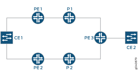
Figure 1 illustrates how a CE device can multihomed to two PE routers. Device CE 1 is multihomed to Routers PE 1 and PE 2. Device CE 2 has two potential paths to reach Device CE 1, and depending on the multihoming mode of redundancy, only one path or both the paths are active at any time. The multihoming mode of operation also determines which PE router or routers forward traffic to the CE device. The PE router forwarding traffic to the CE device (also called a designated forwarder) uses MPLS LSP or GRE tunnels to forward traffic. If a failure occurs over this path, a new designated forwarder is elected to forward the traffic to Device CE 1.
EVPN MPLS Multhoming Features Supported by QFX10000 Switches
Starting in Junos OS 17.4R1, QFX10000 switches support multihoming for EVPN MPLS. Only active-active multihoming is supported. The following subfeatures are supported:
ESI configuration (only type 0 manual configuration and IFD (physical interfaces) are supported)
Aliasing and label route
EVPN Type 4 route (Ethernet segment route)
Extended communities
BUM traffic
Designated Forwarder Election (DF) roles: DF and BDF
QFX10000 switches over an MPLS EVPN core only support the default-switch routing instance. An EVPN instance (EVI) is not supported.
EVPN MPLS Multihoming on ACX5448 Routers
Starting in Junos OS Release 19.4R1, ACX5448 routers support multihoming for EVPN MPLS. Only active-active multihoming is supported. To enable EVPN active-active multihoming on ACX5448 router, include the evpn-mh-profile configuration statement at the [edit system packet-forwarding-options firewall-profile] hierarchy level.
user@host# set system packet-forwarding-options firewall-profile ?
Possible completions:
  default-profile      Set the profile to support default services.
  evpn-mh-profile      Set the profile to support evpn-mh
After changing the profile and committing it, you need to restart the chassis management process by issuing the restart chassis-control CLI command to bring up the new profile.
A syslog warning appears to restart the PFE.
Understanding EVPN Multihoming Concepts
Figure 2 shows a simple EVPN network topology to define EVPN multihoming concepts.
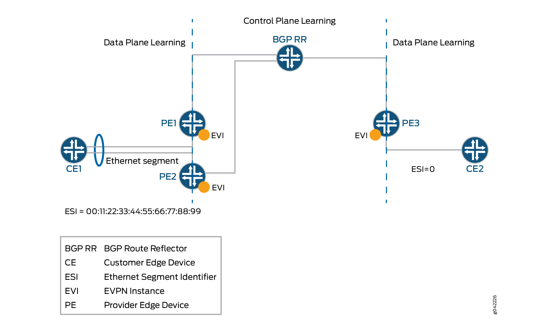
Ethernet segment—When a CE device is multihomed to two or more PE routers, the set of Ethernet links constitutes an Ethernet segment. An Ethernet segment appears as a link aggregation group (LAG) to the CE device.
The links from Routers PE1 and PE2 to Device CE1 form an Ethernet segment.
In active-standby multihoming, the links that constitute an Ethernet segment form a bridge domain. In active-active multihoming, an Ethernet segment appears as a LAG to the CE device.
ESI—An Ethernet segment must have a unique nonzero identifier, called the Ethernet segment identifier (ESI). The ESI is encoded as a 10-octet integer. When manually configuring an ESI value, the most significant octet, known as the type byte, must be 00. When a single-homed CE device is attached to an Ethernet segment, the entire ESI value is zero.
The Ethernet segment of the multihomed Device CE1 has an ESI value of 00:11:22:33:44:55:66:77:88:99 assigned. The single-homed Device CE2 has an ESI value of 0.
EVI—An EVPN instance (EVI) is an EVPN routing and forwarding instance spanning all the PE routers participating in that VPN. An EVI is configured on the PE routers on a per-customer basis. Each EVI has a unique route distinguisher and one or more route targets.
An EVI is configured on Routers PE1, PE2, and PE3.
Ethernet tag—An Ethernet tag identifies a particular broadcast domain, such as a VLAN. An EVPN instance consists of one or more broadcast domains. Ethernet tags are assigned to the broadcast domains of a given EVPN instance by the provider of that EVPN. Each PE router in that EVPN instance performs a mapping between broadcast domain identifiers understood by each of its attached CE devices and the corresponding Ethernet tag.
Ethernet segment route (EVPN Type 4 route)—The PE routers that are connected to a multihomed CE device use BGP Ethernet segment route messages to discover that each of the PE routers is connected to the same Ethernet segment. The PE routers advertise the Ethernet segment route, which consists of an ESI and ES-import extended community.
Routers PE1 and PE2 advertise an ES route with an ES-import extended community (along with other extended communities like the route target). The PE routers also construct a filter that is based on an ES-import extended community, which results in only these PE routers importing the ES route and identifying that they are connected to the same Ethernet segment.
Extended community— An extended community is similar in most ways to a regular community. EVPNs use extended communities because the 4-octet regular community value does not provide enough expansion and flexibility. An extended community is an 8-octet value divided into two main sections.
BUM traffic—This type of traffic is sent to multiple destinations, including broadcast traffic, unknown unicast traffic that is broadcast in the Ethernet segment, and multicast traffic.
DF—When a CE device is multihomed to two or more PE routers, either one or all of the multihomed PE routers are used to reach the customer site depending on the multihoming mode of operation. The PE router that assumes the primary role for forwarding BUM traffic to the CE device is called the designated forwarder (DF).
BDF—Each router in the set of other PE routers advertising the autodiscovery route per Ethernet segment for the same ESI, and serving as the backup path in case the DF encounters a failure, is called a backup designated forwarder (BDF). A BDF is also called a non-DF router.
DF election—On every Ethernet segment, the PE routers participate in a procedure called designated forwarder election to select the DF and the BDF PE routers.
EVPN Multihoming Mode of Operation
The different modes of operation for EVPN multihoming include:
Single—When a PE router is connected to a single-homed customer site, this mode is in operation. The single mode is the default mode of operation, and does not require Ethernet segment values to be configured.
Active-standby—When only a single PE router, among a group of PE routers attached to an Ethernet segment, is allowed to forward traffic to and from that Ethernet segment, the Ethernet segment is defined to be operating in the active-standby redundancy mode.
To configure the active-standby mode, include the ESI value and the
single-activestatement under the[edit interfaces]hierarchy level.Note:We don't support active-standby multihoming mode on QFX Series switches or in EVPN configurations with VXLAN overlays. As a result, if you configure the
single-activeoption on QFX Series switches or in EVPN-VXLAN configurations, the device ignores that configuration item.Active-active—When all PE routers attached to an Ethernet segment are allowed to forward traffic to and from the Ethernet segment, the Ethernet segment is defined to be operating in the active-active redundancy mode.
Note:In Junos OS Release 14.2 and earlier, the EX9200 Series switch supports only the active-standby mode of operation for EVPN multihoming.
Note:Starting with Junos OS Release 14.1x53-D30 for QFX5100 switches and Junos OS Release 18.2R1 for EX4600 switches, these switches support the active-active mode of operation for EVPN multihoming. In this scenario, QFX5100 and EX4600 switches function as top-of-rack (ToR) switches in the data center for virtual networks. EVPN multihoming active-active functionality is used to provide access to the bare-metal servers connected to the top-of-rack switches.
Note:Starting with Junos OS Release 14.1R4, 14.2, 15.1F6, and 16.1R1, Junos OS supports the active-active mode for EVPN multihoming on MX Series routers.
Starting with Junos OS Releases 16.1R4 and 16.2R2, all EX9200 switches support the active-active mode for EVPN multihoming.
Starting with Junos OS Releases 17.4R1 QFX10000 switches support the active-active mode for EVPN multihoming.
To configure the active-active mode, include the ESI value and the
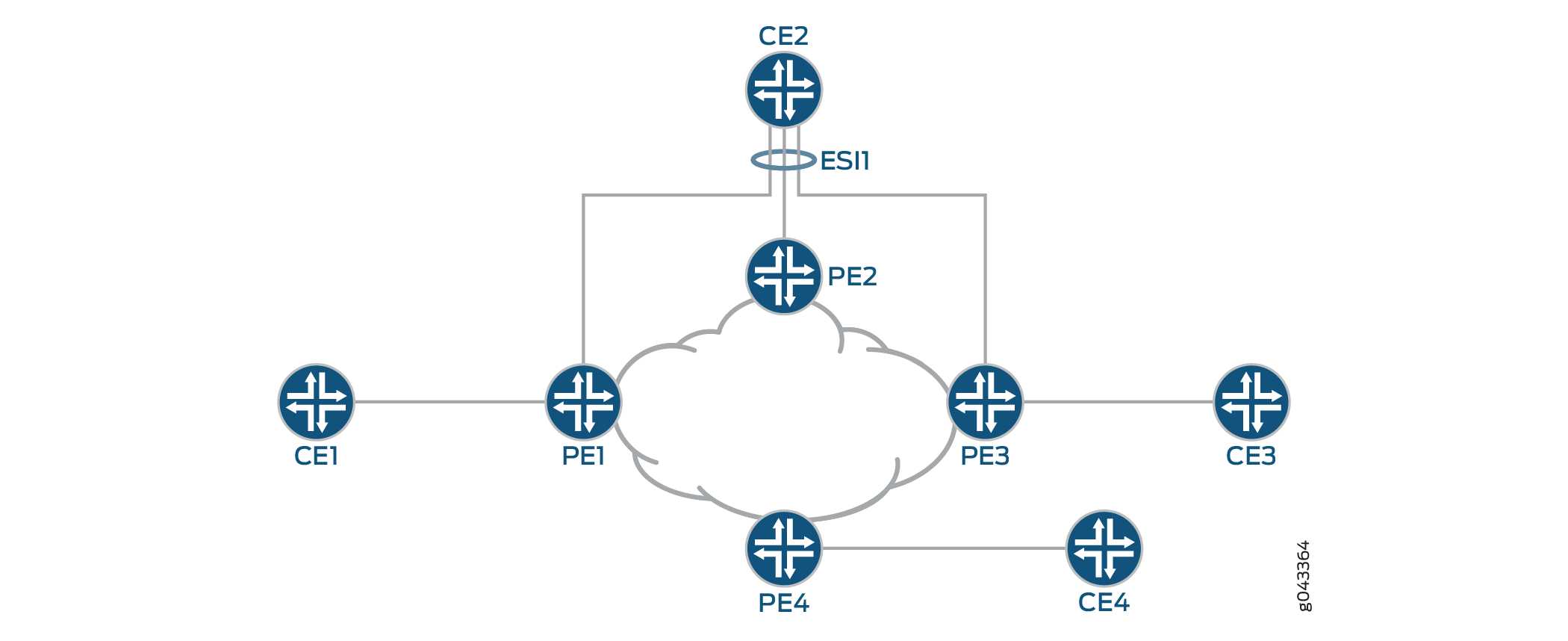
all-activestatement at the[edit interfaces]hierarchy level.Figure 3 shows a reference topology for EVPN active-active multihoming. The ESI1 Ethernet segment for Device CE2 is multihomed to Routers PE1, PE2, and PE3. The Ethernet segment on the CE device can either be configured as a link aggregation group (LAG) or as an ECMP path. Devices CE1 and CE3 are the single-homed customer edge devices and have an ESI value of 0.
EVPN Multihoming Implementation
The EVPN active-standby multihoming mode of operation provides redundancy for access link failures and PE node failure for the multihomed CE device, and is based on the EVPN draft-ietf-l2vpn-evpn-03.
The Junos OS implementation of the EVPN multihoming active-standby and active-active modes of operation includes the following:
- New BGP NLRIs
- New Extended Communities
- Newer EVPN Route Types
- Multihomed Proxy MAC and IP Address Route Advertisement
- Update to the MAC Forwarding Table
- Traffic Flow
- Aliasing
- EVPN Active-Active Multihoming and Multichassis Link Aggregation
- EVPN Active-Active Multihoming and IRB
- Sample Configuration
New BGP NLRIs
To support EVPN multihoming, the following new BGP network layer reachability information (NLRI) routes have been introduced:
Autodiscovery Route per Ethernet Segment
Autodiscovery Route Features
The autodiscovery route NLRI features include:
This is a Type 1 mandatory route, used for fast convergence and for advertising the split horizon label. It is also known as the mass withdraw route.
Type 1 route distinguishers are used with the IP address (loopback) of the originating PE router as the route distinguisher value.
This route carries the ESI in the NLRI (nonzero when it is a multihomed PE, zero otherwise).
The split horizon label is per ESI only, and carries an explicit NULL (0).
The bit in the active-standby flag field in the ESI label extended community is used for signaling the active-standby mode (bit set).
The 3-byte label values in the NLRI and the Ethernet tag is zero.
This route is advertised and imported by all multihomed and remote PE routers that share the same EVI on the advertising ESI.
Autodiscovery Route Advertisement
Active-standby mode
In active-standby mode, the designated forwarder (DF) advertises the autodiscovery route per Ethernet segment with an ESI MPLS label extended community that has the standby bit set to 1. The autodiscovery route is advertised per ESI, and the ESI label is set to 0 when active-standby mode is in operation.
The autodiscovery route is imported by all the multihomed and remote PE routers that are part of the EVI. On receiving the autodiscovery route, the PE routers in the network topology learn that active-standby multihoming mode is in operation for the ESI advertised.
Active-active mode
In active-active mode, each of the multihomed PE device advertises a mandatory autodiscovery route per Ethernet segment as in the active-standby state. However, in the active-active state, the autodiscovery route per Ethernet segment is modified such that the active-standby bit carried in the MPLS extended community is cleared to indicate that the active-active mode is in operation. The autodiscovery route per Ethernet segment in the active-active mode also includes the split horizon label.
In Figure 3, for the ESI1 Ethernet segment, Routers PE1, PE2, and PE3 advertise the autodiscovery route. Router PE4 receives this autodiscovery route.
Autodiscovery Route Withdrawal
The autodiscovery route per Ethernet segment withdrawal may result in mass withdrawal. The mass withdrawal feature is used when there is a link failure on the ESI, or when the ESI configuration changes.
When the link between a multihomed CE device and a multihomed PE device fails, the PE device withdraws the autodiscovery route per Ethernet segment. In such a case, the mass withdrawal feature is handled in the following ways by the other PE devices:
Remote PE device
When a remote PE device receives the BGP update for mass withdrawal, the following is performed at the remote PE device:
The current next hop to reach the remote ESI or CE device is deleted.
A new next hop through the remaining multihomed PE devices is created to reach the remote ESI or CE device.
All the MAC routes behind the CE device are updated with the newly created next hop.
Starting with Junos OS Release 17.4R1, Junos OS supports Dynamic List Next Hops in an EVPN network. Now when the link between the CE device and a multihome PE device fails, the next hop to the ESI or CE is updated, thus reducing the need for a mass withdrawal. For more information on enabling Dynamic List Next Hop, see Configuring Dynamic List Next Hop.
Other multihomed PE device
As a result of the mass withdrawal, load balancing on the multihomed CE device happens because of the following:
When the other multihomed PE devices receive the same set of MAC addresses on the link to the concerned ESI.
In this case, the local routes are preferred. If the remote routes learned from the DF PE device gets withdrawn, it does not affect routes pointing to the local ESI.
When the other multihomed PE devices have not received the same set of MAC addresses on the link to the concerned ESI.
In this case, the PE devices install the MAC routes pointing to the concerned ESI, although the MACs are remotely learned from the DF PE device. When the DF PE device withdraws these routes, the withdrawn routes are flushed. Packets that are destined to the flushed MAC addresses are flooded on all the local segments.
Ethernet Segment Route
Ethernet Segment Route Features
The Ethernet segment route NLRI features include:
This is an EVPN Type 4 route. The purpose of this route is to enable the PE routers connected to the same Ethernet segment to automatically discover each other with minimal configuration on exchanging this route.
This route is associated with an ES-import extended community with an ESI value condensed to 6 bytes, similar to a route target.
This route is advertised and imported only by PE routers that are multihomed on the advertising Ethernet segment.
Ethernet Segment Route Advertisement
The Ethernet segment route is exchanged among all the PE routers within a data center with the ES-import extended community. The ES-import extended community is constructed based on the ESI PE routers that are multihomed, and the Ethernet segment route carries the ESI value related to the Ethernet segment on which the PE routers are multihomed.
The Ethernet segment routes are filtered based on the ES-import extended community, such that only the PE routers that are multihomed on the same Ethernet segment import this route. Each PE router that is connected to a particular Ethernet segment constructs an import filtering rule to import a route that carries the ES-import extended community.
Autodiscovery Route per EVPN Instance
In active-active mode, each of the multihomed PE devices advertise an autodiscovery route per EVPN instance (EVI) with a valid MPLS label. This route is advertised per ESI and is imported by the remote PE devices. The MPLS label included in the autodiscovery route per EVI is used later for aliasing.
New Extended Communities
An extended community is similar in most ways to a regular community. Some networking implementations, such as virtual private networks (VPNs), use extended communities because the 4-octet regular community value does not provide enough expansion and flexibility. An extended community is an 8-octet value divided into two main sections.
To support active-standby multihoming, the following extended communities have been introduced:
ESI-Import
This extended community is attached to the ES route, and is populated from the ESI-import value extracted from the configured ESI value under the interface. To solve the problem of a conflict with another regular route target, the type is set to 0x06, which has been allocated by IANA.
The ESI-import extended community route target populates the list of import route targets configured for the special instance from where the ES route using this community is advertised.
Therefore, incoming ESI routes with the same ESI-import value in the extended community are imported by the PE routers, if the PE router is configured with an Ethernet segment that has the same ESI value. Once the PE router receives a set of these ESI routes that have the same ESI-import extended community value, the DF and BDF election can be done locally.
When the ESI-import extended community is not created implicitly, a policy must be configured to attach all the route targets to the autodiscovery route per Ethernet segment.
Split Horizon
With reference to Figure 3 for example, when a CE device that is multihomed to two or more PE devices on an Ethernet segment (ESI1) and operating in the active-active redundancy mode sends a BUM packet to one of the non-DF PE devices (say PE1), then Device PE1 forwards that packet to all or a subset of the other PE devices in that EVPN instance, including the DF PE device for that Ethernet segment. In this case the DF PE device that the CE device is multihomed to drops the packet without forwarding it back to the CE device. This filtering is referred to as split horizon.
Split horizon signaling
The split horizon extended community is attached to the autodiscovery route per Ethernet segment. The value of the extended community is the split horizon or the Poisson label itself, which is 3 bytes, and is advertised as an opaque attribute.
Split horizon advertisement
In active-standby mode, the standby bit in the split horizon extended community is set to 1, and the ESI split horizon label is set to 0.
In the active-active mode, the split horizon extended community is modified to clear the standby bit to 0 and includes a valid ESI label used for split horizon purposes.
Split horizon MPLS routes
The DF PE device advertises an autodiscovery route per Ethernet segment with a split horizon label A, and an inclusive multicast route with label B for BUM traffic forwarding. On the DF, the BUM packet from the core can come with following labels:
When the non-DF PE devices receive a BUM packet on their single-homed ESIs, the BUM packet is sent to the DF PE device with multicast label B.
When the non-DF PE devices receive a BUM packet on ESI1, the BUM packet is sent to the DF PE device with two MPLS labels — the multicast label B as the outer label, and the split horizon label A as the inner label.
In the EVPN multihoming scenario, the multicast label B has the S-bit set to 1 when it is the only label in the label stack. In this case, the BUM packet needs to be flooded on all the local ESIs on the DF PE device. But the label B has the S-bit set to 0 when split horizon label A is the innermost label in the label stack. In this case, the BUM packets need to be flooded on all local ESIs on the DF PE device, except the ESI that maps to the split horizon label A.
Assuming that packets originated from a multihomed CE device to a non-DF PE device on multihomed segment ESI1, when the non-DF PE device sends this packet to the DF PE device, the ESI label that the DF advertised to the non-DF PE device in its autodiscovery route per Ethernet segment is pushed first. The non-DF PE device also pushes the inclusive multicast label that the DF PE device advertised in its inclusive multicast route and further pushes the LSP label. The MPLS header thus contains two labels within a 32-bit field.
The base EVPN functionality uses a table-next hop to stitch the MPLS table with its corresponding EVPN EVI table. In the EVPN EVI table, the mac-lookup is performed to switch the packet.
The following routes are programmed in the mpls.0 table for EVPN multicast:
The (multicast-label, S=1) route points to the EVPN-EVI table-next hop.
The (multicast-label, S=0) route points to the MPLS table-next hop. This route loops the packet back to the MPLS table after popping the multicast-label.
The (split horizon-label) route points to the EVPN-EVI table-next hop. This is the same table-next hop that is used by the multicast-label, S=1 route.
Newer EVPN Route Types
EVPN multihoming mode supports the following EVPN route types:
Autodiscovery route per Ethernet segment
Autodiscovery route per EVPN instance (EVI)
Ethernet segment route
These route types conform to the following naming convention:
<route-type>:<RD>::<esi>::<route-specific>/304
For example:
Autodiscovery route per Ethernet segment—
1:10.255.0.2:0::112233445566778899::0/304Autodiscovery route per EVI—
1:100.100.100.1:1::22222222222222222222::0/304Ethernet segment route—
4:10.255.0.1:0::112233445566778899:10.255.0.1/304
where:
route-type—Type of EVPN route.1—Autodiscovery route per Ethernet segment.
1—Autodiscovery route per EVI.
4—Ethernet segment route.
5—Route with VXLAN/MPLS encapsulation
RD—Route distinguisher value.The route distinguisher value is set to the IP address of the PE router followed by 0.
esi—Ethernet segment identifier. Displayed as 10 bytes of hexadecimal bytes, and leading 00 bytes are not displayed.route-specific—Differs per route type.Autodiscovery route per Ethernet segment and autodiscovery route per EVI—This value is an MPLS label.
Note:The MPLS label is displayed in the extensive output, although it is not included in the prefix.
Ethernet segment route—This value is the originating IP address.
304—Maximum number of bits in an EVPN route. This is not very useful information and could be removed from the display. However, it might be useful in quickly identifying an EVPN route, either visually or with match operators.
Multihomed Proxy MAC and IP Address Route Advertisement
Starting in Junos OS Release 18.4R1, Junos sends proxy MAC and IP Address route advertisement from PEs that are multihomed to a CE device. Junos uses a proxy flag in the EVPN layer 2 attributes extended community to identify the message as a proxy MAC and IP Address advertisement. A PE that learns of a MAC and IP Address sends a normal EVPN type 2 (MAC and IP Address) route advertisement. The other PEs on the Ethernet Segment that learns of the new route from the remote PE now send a MAC and IP Address route message with the proxy bit set. If the MAC and IP address entry ages out or if the link between the PE and CE fails, the entries has to be relearned and traffic can be lost. This prevents traffic loss when one of the connections to a leaf device fails. Multihomed Proxy MAC is automatically enabled.
Update to the MAC Forwarding Table
In active-standby EVPN multihoming, the MAC addresses are treated as routable addresses, and the MP-IBGP protocol is used to carry the customer MAC addresses. MAC learning at the PE routers does not occur in the data plane but in the control plane. This leads to more control applied in terms of the learning mechanism.
A PE router performs MAC learning in the data plane for packets coming from a customer network for a particular EVI. For CE MAC addresses that are behind other PE routers, the MAC addresses are advertised in BGP NLRI using a new MAC advertisement route type.
The MAC learning is of two types:
Local MAC learning—PE routers must support the local MAC learning process through standard protocols.
Remote MAC learning—Once the local learning process is completed, the PE routers can advertise the locally learned MAC address to remote PE router nodes through MP-IBGP. This process of receiving the remote MAC addresses of attached customers through MP-IBGP is known as the remote MAC learning process.
The MAC advertisement route type is used to advertise locally learned MAC addresses in BGP to remote PE routers. If an individual MAC address is advertised, the IP address field corresponds to that MAC address. If the PE router sees an ARP request for an IP address from a CE device, and if the PE router has the MAC address binding for that IP address, the PE router performs ARP proxy and responds to the ARP request.
The ARP proxy is performed only for the gateway and not for the host.
The MPLS label field depends on the type of allocation. The PE router can advertise a single MPLS label for all MAC addresses per EVI, which requires the least number of MPLS labels and saves the PE router memory. However, when forwarding to the customer network, the PE router must perform a MAC lookup which can cause a delay and increase the number of CPU cycles.
Traffic Flow
In EVPN multihoming, traffic flow is performed in the forwarding-plane. Flood routes are created for flooding the packets, and are used in the following scenarios:
When a packet is received on a local ESI
When a packet is received from the core
The traffic flows in EVPN multihoming can be based on the two traffic types:
Unicast traffic
Unicast traffic is a point-to-point communication with one sender and one receiver. In a multihomed EVPN, unicast traffic is forwarded as follows:
In active-standby mode
CE to core—Traffic is learned and forwarded by the DF PE router.
Core to CE—The remote PE router learns the MAC addresses from the DF, and forwards all unicast traffic to the DF PE router.
In active-active mode
CE to core—Traffic is load-balanced to all the connected multihomed PE devices.
Core to CE—Traffic from the remote PE devices is load-balanced to all the multihomed PE devices connected to the remote CE device.
BUM traffic
Traffic that is sent to multiple destinations, including broadcast traffic, unknown unicast traffic that is broadcast in the Ethernet segment, and multicast traffic is known as BUM traffic. In a multihomed EVPN, BUM traffic is forwarded as follows:
In active-standby mode
CE to core—The CE device floods any BUM traffic to all the links in the Ethernet segment. The DF PE router with the active path forwards the BUM packets to the core. The BDF PE router in the standby mode drops all the traffic from the CE device, because the EVPN multihomed status of the interface is in blocking state. However, if the CE device is connected to the PE devices using separate links or LAGs, the BUM traffic reaches both the DF and BDF PE devices.
Core to CE—The remote PE routers flood all BUM traffic to both the DF and BDF PE routers. Only the DF forwards the BUM traffic to the CE device. The BDF PE router drops all the traffic, because the EVPN multihomed status of the interface is in blocking state.
In active-active mode
Based on the requirements, flooding and switching among local ESIs can be enabled or disabled in the active-active mode. This is referred to as the no-local-switching behavior.
The core of EVPN service provides a full-mesh connectivity among the multihomed PE devices. Because of this, EVPN uses split horizon in the core, so a packet received from the core is never switched or flooded back to the core. Instead, ingress replication is used to replicate the packets to the remote PE devices.
To flood packets to remote PE devices, the multicast and the split horizon next hops are used. The multicast next hop tunnels the packet with the inclusive multicast label, and the split horizon next hop tunnels the packet with a multicast-label and a split horizon label. One such next hop is required per multihomed ESI per remote PE device.
The following flood routes are used in the active-active mode:
All-CE flood route
This flood route is used by the local ESIs for the following:
Flooding the packet on the local ESIs (when local-switching is allowed).
Flooding the packet to the remote PE devices. The remote PE devices flood the packet on their local ESIs.
Because BUM traffic is forwarded only by the designated forwarder (DF), and not by the non-DF multihomed PE devices, the non-DFs use the split horizon next hop to flood this packet to other PE devices. However, the multihomed local ESIs for which the PE device is a non-DF does not participate in the flooding.
The all-CE flood route is not used by the non-DF ESIs, and the next hop for these flood routes is created accordingly. In such cases, the non-DF ESI flood route is used.
All-VE flood route
This flood route is used when the packet is received from the core. It is used for flooding the packet received from the core to the local ESIs. Because the packet received from the core can come with multicast-label only or with both multicast-label and split horizon label, appropriate forwarding rules must be followed to drop the packet on the multihomed ESI that maps to the split horizon label.
Non-DF flood route
This flood route is used for the following:
Flooding the packet on the local ESIs.
Flooding the packet to the remote PE devices using ingress replication with SH-label for the DF for the ESI.
Aliasing
Starting in Junos OS Release 15.1, Junos OS supports aliasing in an EVPN. Aliasing is the ability of a remote PE device to load balance Layer 2 unicast traffic on all the other PE devices that have same Ethernet segment towards a CE device.
Aliasing in the Active-Active Mode
In Figure 3, aliasing in the active-active mode works as follows:
ESI1 is configured on Routers PE1, PE2, and PE3. Routers PE1, PE2, and PE3 advertise the autodiscovery route per Ethernet segment for ESI1.
Device CE1 sends Layer 2 traffic with source MAC address (MAC1) to Router PE1.
Router PE1 learns the MAC1 address on (ESI1, vlan X) and advertises it to all PE routers using BGP.
Router PE4 receives the MAC1 route through BGP.
Because Router PE4 also received the autodiscovery route per EVI from Routers PE2 and PE3, it knows that MAC1 must be reachable through Routers PE2 and PE3. Router PE4 builds its forwarding state to load-balance the Layer 2 traffic for MAC1 among Routers PE1, PE2, and PE3.
Aliasing and Autodiscovery Routes
Autodiscovery routes from Routers PE2 and PE3 can come in any order. As a result, these routes are installed by the Layer 2 process as follows:
After receiving MAC1 from Router PE1, and if any autodiscovery routes have not been received by Router PE4, MAC1 is programmed by PE4 with a next hop pointing toward Router PE1. When PE4 receives the autodiscovery route from Router PE2 for the same ESI, the next hop is installed so the traffic for MAC1 is load-balanced to Routers PE1 and PE2. When PE4 receives the autodiscovery route from Router PE3 for the same ESI, the next hop is updated to load-balance the traffic for MAC1 among Routers PE1, PE2, and PE3.
If Router PE4 has already received the autodiscovery routes from more than one PE device (PE1, PE2, and PE3), PE4 installs the MAC routes with the multi-destination next hop.
Aliasing and Label Route
Any PE device that advertises the autodiscovery route per EVI with a valid MPLS label programs the advertised label in the mpls.0 routing table. For instance, if Router PE2 advertised the autodiscovery route per EVI with label A, the mpls.0 entry is as follows:
Label A route points to the EVPN-EVI table-next hop.
When the remote Router PE4 sends a unicast data packet toward Router PE2 with this label A, lookup is done in Router PE2’s forwarding table, and as a result of this lookup, the packet is forwarded on ESI1.
Aliasing and Unicast Packet Forwarding
When the unicast packets for MAC1 come from the remote Router PE4 to Router PE2, there could be two cases:
Router PE2 also received the same set of MACs on its link to ESI1—In this case, local routes are preferred and as a result of the MAC lookup, packets are forwarded to ESI1.
Router PE2 has not received the same set of MACs on its link to ESI1—In this case, Router PE2 still installs MAC routes pointing to ESI1, although MACs are remotely learned from Router PE1. As a result, the packets are forwarded to ESI1.
EVPN Active-Active Multihoming and Multichassis Link Aggregation
When a CE device is configured with a LAG toward the PE devices, the following two options are available to run LACP on the PE devices:
Configure the same LACP system ID on all the PE devices.
Configure multichassis link aggregation on the PE devices.
When multichassis link aggregation is configured with EVPN, a reduced set of procedures for active-active multichassis link aggregation are required. These procedures provide link and node level redundancy. The multichassis link aggregation is completely transparent to the CE device, and is realized as pure LAG. Multichassis link aggregation operates at the port level as well. This essentially means that if multichassis link aggregation is configured as active-active, all VLANs on the multichassis link aggregation ports work in the active-active multihoming mode.
When multichassis link aggregation is configured along with EVPN, the following is considered:
Both multichassis link aggregation and EVPN ESI must be enabled to work in the active-active mode only.
The following functions are not required for multichassis link aggregation with EVPN:
Mac synchronization—This is performed in the BGP control plane of EVPN.
ICL linking—This is handled by the aliasing feature of EVPN.
ARP synchronization—This is handled by the BGP control plane with IRB functionality.
EVPN Active-Active Multihoming and IRB
When IRB is configured, the EVPN routes contain both MAC and IP information. The active-active multihoming requires ARP synchronization among the multihomed PE devices because the ARP responses can get hashed to a particular PE device.
Sample Configuration
The following is a sample configuration for EVPN active-standby multihoming on the following types of interfaces:
Ethernet interface configuration
ge-0/1/2 {
    encapsulation ethernet-bridge;
    esi XX:XX:XX:XX:XX:XX:XX:XX:XX:XX;
    unit 0 {
        family bridge;
    }
}
Single VLAN interface configuration
ge-0/1/3 {
    encapsulation extended-vlan-bridge;
    esi XX:XX:XX:XX:XX:XX:XX:XX:XX:XX;
    vlan-tagging
    unit 0 {
        family bridge;
        vlan-id 1;
    }
}
An ESI value of 0 and all FFs are reserved and are not used for configuring a multihomed Ehernet segment.
Two interfaces in the same EVI cannot be configured with the same ESI value.
The following is a sample routing instance configuration for EVPN active-standby multihoming:
Routing instance configuration
routing-instances {
    evpn-0 {
        instance-type evpn;
        route-distinguisher value;
        vrf-target value;
        vlan-id vlan-ID;
        interface ge-0/1/2.0;
        interface ge-1/1/1.0;
        interface ge-2/2/2.0;

        protocols {
            evpn {
                designated-forwarder-election-hold-time time;
            }
        }
    }
}
With the active-standby mode configuration, the autodiscovery route per Ethernet segment is advertised with the active-standby bit set to 1 for each Ethernet segment.
Designated Forwarder Election
The designated forwarder (DF) election procedure in EVPN provides a robust mechanism for electing a designated forwarder among the devices that serve a multihomed Ethernet segment. The DF election ensures efficient and effective broadcast, unknown unicast, and multicast (BUM) traffic forwarding, load balancing, high availability, and traffic management. Key features include:
-
Modulo based or preference-based algorithms for DF selection.
-
Dynamic DF re-election triggered by network state changes.
-
DF and Backup DF roles to prevent traffic loops.
The system also processes ESI routes to optimize route processing, and uses mass withdrawal mechanisms to maintain network integrity. You can use these features and their CLI configurations to ensure seamless traffic flow and effectively manage your EVPN multihoming scenarios.
For more information, see EVPN Multihoming Designated Forwarder Election.
ESIs on Physical, Aggregated Ethernet, and Logical Interfaces
In releases before Junos OS Release 15.1F6 and 17.1R1 for MX Series routers and Junos OS Release 17.3R1 for EX9200 switches, you can specify an ESI only on a physical or aggregated Ethernet interface, for example, set interfaces ae0 esi 00:11:22:33:44:55:66:77:88:99. If you specify an ESI on a physical or aggregated Ethernet interface, keep in mind that an ESI is a factor in the designated forwarder (DF) election process. For example, assume that you configure EVPN multihoming active-standby on aggregated Ethernet interface ae0, and given the ESI configured on ae0 and other determining factors, the DF election results in ae0 being in the down state. Further, all logical interfaces configured on aggregated Ethernet interface ae0, for example, set interfaces ae0 unit 1 and set interfaces ae0 unit 2 are also in the down state, which renders logical interfaces ae0.1 and ae0.2 unable to provide services to their respective customer sites (VLANs).
To better utilize logical interfaces in EVPN multihoming active-standby or active-active mode, starting with Junos OS Releases 15.1F6 and 17.1R1 for MX Series routers and Junos OS Release 17.3R1 for EX9200 switches, you can specify an ESI on a logical interface. As a result, even if a logical interface is a non-DF, other logical interfaces on the same physical or aggregated Ethernet interface are still able to provide services to their respective customer sites (VLANs).
For more information, see Example: Configuring an ESI on a Logical Interface With EVPN Multihoming.
Automatically Generated ESIs
Starting with Junos OS Release 18.4R1, you can configure aggregated Ethernet interfaces and aggregated Ethernet logical interfaces to automatically derive ESIs from the LACP configuration. We support this feature in the following environments:
On Juniper Networks devices that support this feature and are multihomed in active-active mode in an EVPN-VXLAN overlay network.
On Juniper Networks devices that support this feature and are multihomed in active-standby or active-active mode in an EVPN-MPLS overlay network.
For more information, see Understanding Automatically Generated ESIs in EVPN Networks.
Convergence in an EVPN Network
When there are changes in the network topology in a large-scale EVPN system, the convergence time might be significant. You can prioritize NLRI updates that are critical to route selection in routing policies to improve convergence. Table 1 lists the NLRI route types and the priority that must be configured in the routing policy.
NLRI Route Type |
Description |
Priority |
|---|---|---|
NLRI Route Type 1 |
Ethernet auto-discovery route—Type 1 supports fast convergence and aliasing and is used to signal MAC mass withdrawal. |
High |
NLRI Route Type 2 |
MAC/IP advertisement route—Type 2 is used to advertise MAC addresses and IP addresses in EVPN networks. |
Low |
NLRI Route Type 3 |
Inclusive multicast Ethernet tag—Type 3 is used to set up a path for BUM traffic. |
Low |
NLRI Route Type 4 |
Ethernet segment route—EVPN Type 4 is used in the selection of a designated forwarder. |
High |
To prioritize the NLRI route type, set the bgp-output-queue-priority priority
for nlri-route-type at the [edit policy-options
policy-statement] hierarchy level on all provider edge routers and
route reflectors in the EVPN network. In this example, a high priority was
configured for NLRI route type 1 and NLRI route Type 4.
user@PE1#show policy-options
policy-statement evpn-rt-priority-policy {
    term 1 {
        from {
            family evpn;
            nlri-route-type 1;
        }
        then {
            bgp-output-queue-priority priority 16;
        }
    }
    term 2 {
        from {
            family evpn;
            nlri-route-type 2;
        }
        then {
            bgp-output-queue-priority priority 1;
        }
    }
    term 3 {
        from {
            family evpn;
            nlri-route-type 3;
        }
        then {
            bgp-output-queue-priority priority 2;
        }
    }
    term 4 {
        from {
            family evpn;
            nlri-route-type 4;
        }
        then {
            bgp-output-queue-priority priority 16;
        }
    }
}There are 17 prioritized output queues: an expedited queue that has the highest priority, and 16 numbered queues for which1 is the lowest priority and 16 is the highest.
For more information about how to configure routing policies, see Routing Policies, Firewall Filters, and Traffic Policers User Guide.
Change History Table
Feature support is determined by the platform and release you are using. Use Feature Explorer to determine if a feature is supported on your platform.