Example: Configuring an EVPN-VXLAN Edge-Routed Bridging Fabric with an Anycast Gateway
Ethernet VPN (EVPN) is a BGP-based control plane technology that enables hosts (physical servers and virtual machines) to be placed anywhere in a network and remain connected to the same logical Layer 2 (L2) overlay network. Virtual Extensible LAN (VXLAN) is a tunneling protocol that creates the data plane for the L2 overlay network.
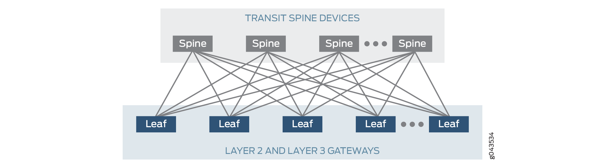
The physical underlay network over which EVPN-VXLAN is commonly deployed is a two-layer IP fabric, which includes spine and leaf devices as shown in Figure 1 . A two-layer spine and leaf fabric is referred to as a 3-stage Clos.
This example details how to deploy an edge-routed bridging (ERB) architecture using a 3-stage Clos fabric. In this design, the spine devices (such as QFX10000 switches) provide only IP connectivity between the leaf devices. In this capacity we call the spine devices lean spines, as they require no VXLAN functionality. The leaf devices (such as QFX5100 switches) provide connectivity to attached workloads. In the ERB case, the leaf devices provide L2 and Layer 3 (L3) VXLAN functionality in the overlay network. L2 gateways provide bridging within the same VLAN. An L3 gateway handles traffic between VLANs (inter-VLAN), using integrated routing and bridging (IRB) interfaces.
In this example, the IRB interfaces are configured with an anycast IP address. For an ERB example that uses virtual gateway address (VGA) IP address, see Example: Configuring an EVPN-VXLAN Edge-Routed Bridging Fabric With a Virtual Gateway
We also call the ERB architecture a "collapsed" fabric. Compared with a CRB design, the L2 and L3 VXLAN gateway functions collapse into a single layer of the fabric (the leaves).
For background on EVPN-VXLAN technology and supported architectures, see EVPN Primer.
For an example of how to configure an EVPN-VXLAN centrally-routed bridging (CRB) overlay, see Example: Configure an EVPN-VXLAN Centrally-Routed Bridging Fabric.
This example describes how to configure an EVPN-VXLAN ERB overlay. As a result, you configure routing instances and IRB interfaces on the leaf devices only.
Requirements
This example uses the following hardware and software components:
-
Two devices that function as transit spine devices.
-
Four devices running Junos OS Release 15.1X53-D60 or later software that serve as leaf devices and provide both L2 and L3 gateway functionality.
- Updated and re-validated using QFX10002 switches running Junos OS Release 21.3R1
- See the hardware summary for a list of supported platforms.
Overview and Topology
The ERB overlay shown in Figure 2 includes two transit spine devices and four leaf devices that function as both L2 and L3 gateways. Four servers are attached to the leaf devices. Server A is connected to Leaf1 and Leaf2 through a link aggregation group (LAG) interface. On both leaf devices, the interface is assigned the same Ethernet segment identifier (ESI) and set to multihoming all-active mode.
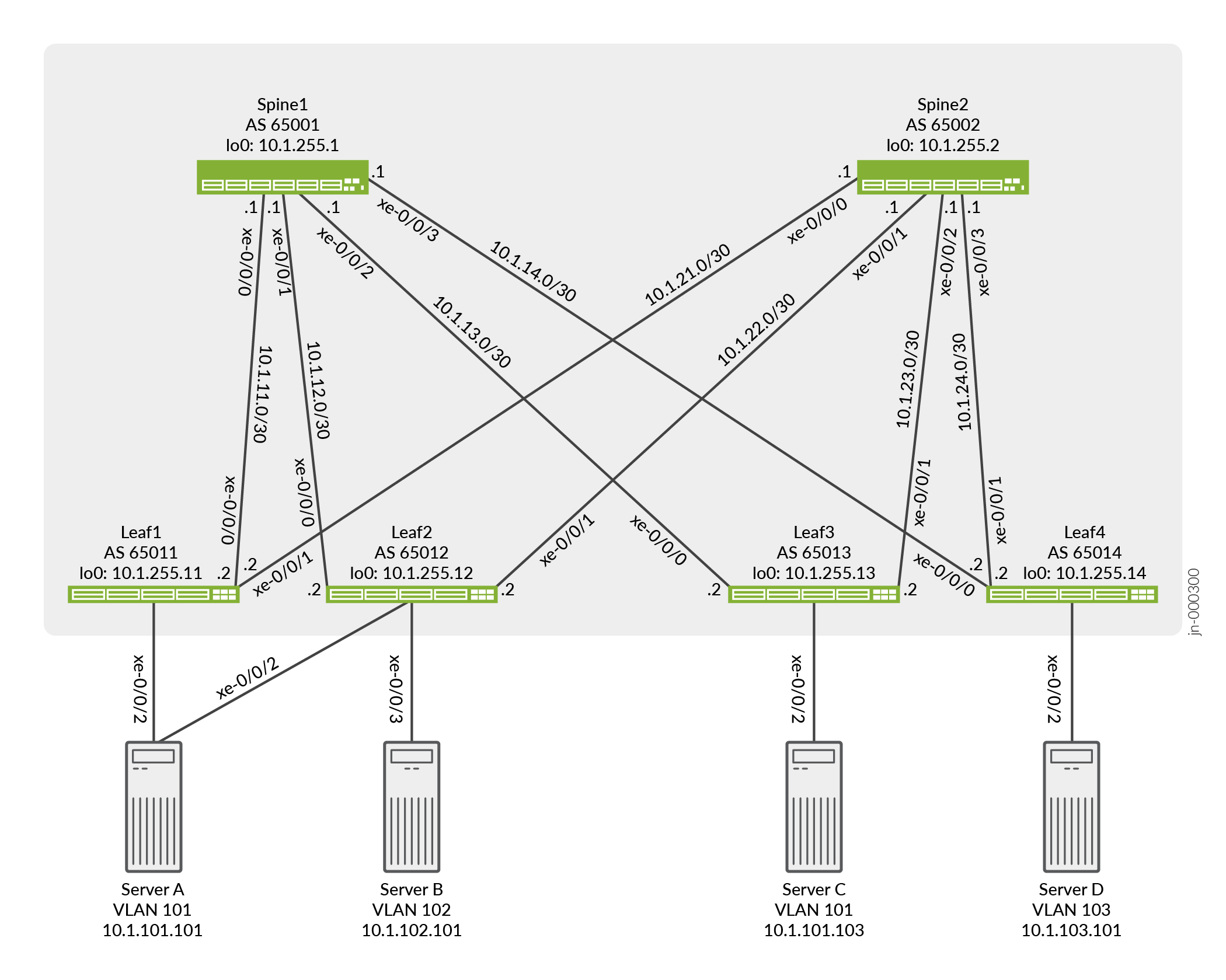
In this topology, Server A and Server C are in VLAN 101, Server B is in VLAN 102, and Server D is in VLAN 103. For communication between VLANs to occur, you must configure IRB interfaces for each VLAN on all leaf devices.
The most significant difference between the configuration of ERB compared with CRB is the configuration and location of the L3 gateway. Therefore, this example focuses on the EVPN-VXLAN configuration, in particular, the L3 gateway configuration, on the leaf devices.
For an ERB overlay, you can configure the IRB interfaces within an EVPN instance (EVI) using one of the following methods:
-
Method 1—This method entails a unique IP address for each IRB interface, but uses the same MAC for each IRB interface. With this method a single MAC entry is installed for each IRB address on both the leaf devices and servers. For each IRB interface on a particular leaf device, for example, Leaf1, you specify the following:
-
A unique IP address for each IRB interface.
-
The same MAC address is used for each IRB interface.
For example:
Table 1: Unique IP Address with Same MAC per IRB Interface irb.101
IP address: 10.1.101.254/24
MAC address: 00:00:5e:00:53:01
irb.102
IP address: 10.1.102.254/24
MAC address: 00:00:5e:00:53:01
irb.103
IP address: 10.1.103.254/24
MAC address: 00:00:5e:00:53:01
-
-
Method 2—This method entails a unique IP address and MAC for each IRB interface. With this method, a MAC entry is installed for each IRB address on the leaf devices but only a single MAC on the servers. For each IRB interface on Leaf1, you specify the following:
-
A unique IP address for each IRB interface.
-
A unique MAC address is used for each IRB interface..
For example:
Table 2: Unique IP Address and MAC per IRB Interface irb.101
IP address: 10.1.101.254/24
MAC address: 00:00:5e:00:53:01
irb.102
IP address: 10.1.102.254/24
MAC address: 00:00:5e:00:53:02
irb.103
IP address: 10.1.103.254/24
MAC address: 00:00:5e:00:53:03
-
-
Method 3—This method entails a unique IP address and VGA for each IRB interface. With this method a MAC entry is installed for each IRB address and the VGA on the leaf devices and servers. For each IRB interface on Leaf1, you specify the following:
-
A unique IP address for each IRB interface.
-
A unique VGA address for each IRB interface.
For example:
Table 3: Unique IP Address and Virtual Gateway Address per IRB Interface irb.101
IP address: 10.1.101.1/24
VGA address: 10.1.101.254
irb.102
IP address: 10.1.102.1/24
VGA address: 10.1.102.254
irb.103
IP address: 10.1.103.1/24
VGA address: 10.1.103.254
-
For methods 1 and 2, the same IRB interface configuration is applied across all leaf devices. For method 3, a unique IRB interface address and the same VGA is applied across all leaf devices. In this example, method 1 is used to configure the IRB interfaces.
This example (with method 1) configures the same MAC address for each IRB interface on each leaf device. Each host uses the same MAC address when sending inter-VLAN traffic regardless of where the host is located or which leaf device receives the traffic. For example, in the topology shown in Figure 2, multi-homed Server A in VLAN 101 sends a packet to Server B in VLAN 102. If Leaf1 is down, Leaf2 continues to forward the inter-VLAN traffic even without the configuration of a redundant default gateway MAC address.
The IRB interfaces configuration in this example doesn't include a virtual gateway address (VGA) and a corresponding V-MAC address that establishes redundant default gateway functionality, which is mentioned above. By configuring the same MAC address for each IRB interface on each leaf device, hosts use the local leaf device configured with the common MAC address as the default L3 gateway.
Therefore, you eliminate the need to advertise a redundant default gateway and
dynamically synchronize the MAC addresses of the redundant default gateway throughout the
EVPN control plane. As a result, when configuring each leaf device, you must disable the
advertisement of the redundant default gateway by including the default-gateway
do-not-advertise configuration statement at the [edit protocols
evpn] hierarchy level in your configuration.
Also, although the IRB interface configuration used in this example does not include a VGA, you can configure a VGA as needed to make EVPN-VXLAN work properly in your ERB overlay. If you configure a VGA for each IRB interface, you specify the same IP address for each VGA on each leaf device instead of configuring the same MAC address for each IRB interface on each leaf device as is shown in this example.
When it comes to handling the replication of broadcast, unknown unicast, and multicast (BUM) traffic, note that the configuration on Leaf1:
-
includes the
set protocols evpn multicast-mode ingress-replicationcommand. This command causes Leaf1, which is a hardware VTEP, to handle replicating and sending BUM traffic instead of relying on a multicast-enabled underlay.
Configuration For Leaf1
CLI Quick Configuration
To quickly configure this example, copy the following commands and paste them into a text
file. Remove any line breaks, and change any details necessary to match your network
configuration. Then copy and paste the commands into the CLI at the
[edit] hierarchy level.
Leaf1
set chassis aggregated-devices ethernet device-count 1
set interfaces xe-0/0/0 unit 0 family inet address 10.1.11.2/30
set interfaces xe-0/0/1 unit 0 family inet address 10.1.21.2/30
set interfaces xe-0/0/2 ether-options 802.3ad ae0
set interfaces ae0 esi 00:01:01:01:01:01:01:01:01:01
set interfaces ae0 esi all-active
set interfaces ae0 aggregated-ether-options lacp active
set interfaces ae0 aggregated-ether-options lacp system-id 00:01:01:01:01:01
set interfaces ae0 unit 0 family ethernet-switching interface-mode trunk
set interfaces ae0 unit 0 family ethernet-switching vlan members v101
set interfaces irb unit 101 family inet address 10.1.101.254/24
set interfaces irb unit 101 mac 00:00:5e:00:53:01
set interfaces irb unit 102 family inet address 10.1.102.254/24
set interfaces irb unit 102 mac 00:00:5e:00:53:01
set interfaces irb unit 103 family inet address 10.1.103.254/24
set interfaces irb unit 103 mac 00:00:5e:00:53:01
set interfaces lo0 unit 0 family inet address 10.1.255.11/32
set policy-options policy-statement load-balancing-policy then load-balance per-packet
set policy-options policy-statement send-direct term 1 from protocol direct
set policy-options policy-statement send-direct term 1 from route-filter 10.1.255.11/32 exact
set policy-options policy-statement send-direct term 1 then accept
set routing-instances vrf101 instance-type vrf
set routing-instances vrf101 interface irb.101
set routing-instances vrf101 interface irb.102
set routing-instances vrf101 interface irb.103
set routing-instances vrf101 route-distinguisher 10.1.255.11:101
set routing-instances vrf101 vrf-target target:1001:1
set routing-options router-id 10.1.255.11
set routing-options autonomous-system 65011
set routing-options forwarding-table export load-balancing-policy
set protocols bgp group underlay type external
set protocols bgp group underlay export send-direct
set protocols bgp group underlay multipath multiple-as
set protocols bgp group underlay neighbor 10.1.11.1 peer-as 65001
set protocols bgp group underlay neighbor 10.1.21.1 peer-as 65002
set protocols bgp group overlay type external
set protocols bgp group overlay multihop
set protocols bgp group overlay local-address 10.1.255.11
set protocols bgp group overlay family evpn signaling
set protocols bgp group overlay multipath multiple-as
set protocols bgp group overlay neighbor 10.1.255.1 peer-as 65001
set protocols bgp group overlay neighbor 10.1.255.2 peer-as 65002
set protocols evpn encapsulation vxlan
set protocols evpn default-gateway do-not-advertise
set protocols evpn multicast-mode ingress-replication
set protocols evpn vni-options vni 101 vrf-target target:101:1
set protocols evpn vni-options vni 102 vrf-target target:102:1
set protocols evpn vni-options vni 103 vrf-target target:103:1
set protocols evpn extended-vni-list all
set switch-options vtep-source-interface lo0.0
set switch-options route-distinguisher 10.1.255.11:1
set switch-options vrf-target target:1:1
set switch-options vrf-target auto
set vlans v101 vlan-id 101
set vlans v101 l3-interface irb.101
set vlans v101 vxlan vni 101
set vlans v102 vlan-id 102
set vlans v102 l3-interface irb.102
set vlans v102 vxlan vni 102
set vlans v103 vlan-id 103
set vlans v103 l3-interface irb.103
set vlans v103 vxlan vni 103
Configuring EVPN-VXLAN on Leaf1
Step-by-Step Procedure
-
Configure the underlay configuration. In this example we use EBGP for the underlay routing protocol.
[edit]
user@leaf1# set interfaces xe-0/0/0 unit 0 family inet address 10.1.11.2/30
user@leaf1# set interfaces xe-0/0/1 unit 0 family inet address 10.1.21.2/30
user@leaf1# set interfaces lo0 unit 0 family inet address 10.1.255.11/32
user@leaf1# set policy-options policy-statement load-balancing-policy then load-balance per-packet
user@leaf1# set policy-options policy-statement send-direct term 1 from protocol direct
user@leaf1# set policy-options policy-statement send-direct term 1 from route-filter 10.1.255.11/32 exact
user@leaf1# set policy-options policy-statement send-direct term 1 then accept
user@leaf1# set routing-options router-id 10.1.255.11
user@leaf1# set routing-options autonomous-system 65011
user@leaf1# set routing-options forwarding-table export load-balancing-policy
user@leaf1# set protocols bgp group underlay type external
user@leaf1# set protocols bgp group underlay export send-direct
user@leaf1# set protocols bgp group underlay multipath multiple-as
user@leaf1# set protocols bgp group underlay neighbor 10.1.11.1 peer-as 65001
user@leaf1# set protocols bgp group underlay neighbor 10.1.21.1 peer-as 65002
-
Configure Server A to be multihomed to Leaf1 and Leaf2 by configuring an aggregated Ethernet interface, specifying an ESI for the interface, and setting the mode so that the connections to both leaf devices are active. We show the applied VLAN configuration in a later step.
Note:When configuring the AE interface on Leaf2, you must specify the same ESI (00:01:01:01:01:01:01:01:01:01) as the ESI for the same interface on Leaf1.
[edit]
user@leaf1# set chassis aggregated-devices ethernet device-count 1
user@leaf1# set interfaces xe-0/0/2 ether-options 802.3ad ae0
user@leaf1# set interfaces ae0 esi 00:01:01:01:01:01:01:01:01:01
user@leaf1# set interfaces ae0 esi all-active
user@leaf1# set interfaces ae0 aggregated-ether-options lacp active
user@leaf1# set interfaces ae0 aggregated-ether-options lacp system-id 00:01:01:01:01:01
user@leaf1# set interfaces ae0 unit 0 family ethernet-switching interface-mode trunk
user@leaf1# set interfaces ae0 unit 0 family ethernet-switching vlan members v101
-
Configure the IRB interfaces, each with unique IP addresses and the same MAC address.
Note:Each leaf device should have the same IRB interface configuration.
[edit]
user@leaf1# set interfaces irb unit 101 family inet address 10.1.101.254/24
user@leaf1# set interfaces irb unit 101 mac 00:00:5e:00:53:01
user@leaf1# set interfaces irb unit 102 family inet address 10.1.102.254/24
user@leaf1# set interfaces irb unit 102 mac 00:00:5e:00:53:01
user@leaf1# set interfaces irb unit 103 family inet address 10.1.103.254/24
user@leaf1# set interfaces irb unit 103 mac 00:00:5e:00:53:01
-
Set up the EBGP-based overlay configuration. Make sure to include the
multihopconfiguration option because we use loopback peering.[edit] user@leaf1# set protocols bgp group overlay type external user@leaf1# set protocols bgp group overlay multihop user@leaf1# set protocols bgp group overlay local-address 10.1.255.11 user@leaf1# set protocols bgp group overlay family evpn signaling user@leaf1# set protocols bgp group overlay multipath multiple-as user@leaf1# set protocols bgp group overlay neighbor 10.1.255.1 peer-as 65001 user@leaf1# set protocols bgp group overlay neighbor 10.1.255.2 peer-as 65002
Note:Some IP fabrics use an IBGP based EVPN-VXLAN overlay. For an example of an IP fabric that uses IBGP for the overlay, see Example: Configure an EVPN-VXLAN Centrally-Routed Bridging Fabric. Note that choosing EBGP or IBGP for the overlay does not impact the fabric architecture. Both CRB and ERB designs support either type of overlay.
-
Set up the EVPN-VXLAN domain, which entails determining which VNIs are included in the domain, specifying that Leaf1, which is a hardware VTEP, handles the replication and sending of BUM traffic, disabling the advertisement of the redundant default gateway throughout the EVPN control plane, and specifying a route target for each VNI.
[edit]
user@leaf1# set protocols evpn encapsulation vxlan
user@leaf1# set protocols evpn default-gateway do-not-advertise
user@leaf1# set protocols evpn multicast-mode ingress-replication
user@leaf1# set protocols evpn vni-options vni 101 vrf-target target:101:1
user@leaf1# set protocols evpn vni-options vni 102 vrf-target target:102:1
user@leaf1# set protocols evpn vni-options vni 103 vrf-target target:103:1
user@leaf1# set protocols evpn extended-vni-list all
-
Set up an EVPN routing instance.
[edit]
user@leaf1# set routing-instances vrf101 instance-type vrf
user@leaf1# set routing-instances vrf101 interface irb.101
user@leaf1# set routing-instances vrf101 interface irb.102
user@leaf1# set routing-instances vrf101 interface irb.103
user@leaf1# set routing-instances vrf101 route-distinguisher 10.1.255.11:101
user@leaf1# set routing-instances vrf101 vrf-target target:1001:1
-
Configure the switch options to use loopback interface lo0.0 as the source interface of the VTEP, set a route distinguisher, and set the vrf target.
[edit]
user@leaf1# set switch-options vtep-source-interface lo0.0
user@leaf1# set switch-options route-distinguisher 10.1.255.11:1
user@leaf1# set switch-options vrf-target target:1:1
user@leaf1# set switch-options vrf-target auto
-
Configure VLANs associated with IRB interfaces and VXLAN VNIs.
[edit]
user@leaf1# set vlans v101 vlan-id 101
user@leaf1# set vlans v101 l3-interface irb.101
user@leaf1# set vlans v101 vxlan vni 101
user@leaf1# set vlans v102 vlan-id 102
user@leaf1# set vlans v102 l3-interface irb.102
user@leaf1# set vlans v102 vxlan vni 102
user@leaf1# set vlans v103 vlan-id 103
user@leaf1# set vlans v103 l3-interface irb.103
user@leaf1# set vlans v103 vxlan vni 103
Verification
The section describes the following verifications for this example:
Verifying BGP
Purpose
Verify that the spine devices have established BGP session connectivity.
Action
Display the BGP summary:
user@leaf1> show bgp summary
Threading mode: BGP I/O
Default eBGP mode: advertise - accept, receive - accept
Groups: 2 Peers: 4 Down peers: 0
Table          Tot Paths  Act Paths Suppressed    History Damp State    Pending
bgp.evpn.0
                      76         38          0          0          0          0
inet.0
                       8          8          0          0          0          0
Peer                     AS      InPkt     OutPkt    OutQ   Flaps Last Up/Dwn State|#Active/Received/Accepted/Damped...
10.1.11.1             65001       3826       3867       0       0  1d 5:14:55 Establ
  inet.0: 4/4/4/0
10.1.21.1             65002       3829       3871       0       0  1d 5:14:55 Establ
  inet.0: 4/4/4/0
10.1.255.1            65001       4321       4228       0       0  1d 5:14:52 Establ
  bgp.evpn.0: 14/38/38/0
  default-switch.evpn.0: 13/37/37/0
  __default_evpn__.evpn.0: 1/1/1/0
10.1.255.2            65002       4385       4169       0       0  1d 5:14:53 Establ
  bgp.evpn.0: 24/38/38/0
  default-switch.evpn.0: 24/37/37/0
  __default_evpn__.evpn.0: 0/1/1/0
Meaning
Both underlay and overlay BGP sessions are established with the spine devices.
Verifying the ESI
Purpose
Verify the status of the ESI.
Action
Display the status of the ESI:
user@leaf1> show evpn instance esi 00:01:01:01:01:01:01:01:01:01 extensive
Instance: default-switch
  Route Distinguisher: 10.1.255.11:1
  Encapsulation type: VXLAN
  Duplicate MAC detection threshold: 5
  Duplicate MAC detection window: 180
  MAC database status                     Local  Remote
    MAC advertisements:                       4       4
    MAC+IP advertisements:                    4       4
    Default gateway MAC advertisements:       3       0
  Number of local interfaces: 2 (2 up)
    Interface name  ESI                            Mode             Status     AC-Role
    .local..5       00:00:00:00:00:00:00:00:00:00  single-homed     Up         Root
    ae0.0           00:01:01:01:01:01:01:01:01:01  all-active       Up         Root
  Number of IRB interfaces: 3 (3 up)
    Interface name  VLAN   VNI    Status  L3 context
    irb.101                101     Up     vrf101
    irb.102                102     Up     vrf101
    irb.103                103     Up     vrf101
  Number of protect interfaces: 0
  Number of bridge domains: 3
    VLAN  Domain-ID Intfs/up   IRB-intf  Mode            MAC-sync IM-label  MAC-label  v4-SG-sync IM-core-NH v6-SG-sync IM-core-NH Trans-ID
    101   101          1  1    irb.101   Extended        Enabled  101                 Disabled              Disabled              101
    102   102          0  0    irb.102   Extended        Enabled  102                 Disabled              Disabled              102
    103   103          0  0    irb.103   Extended        Enabled  103                 Disabled              Disabled              103
  Number of neighbors: 3
    Address               MAC    MAC+IP        AD        IM        ES Leaf-label Remote-DCI-Peer
    10.1.255.12             2         2         2         3         0
    10.1.255.13             1         1         0         3         0
    10.1.255.14             1         1         0         3         0
  Number of ethernet segments: 4
    ESI: 00:01:01:01:01:01:01:01:01:01
      Status: Resolved by IFL ae0.0
      Local interface: ae0.0, Status: Up/Forwarding
      Number of remote PEs connected: 1
        Remote-PE        MAC-label  Aliasing-label  Mode
        10.1.255.12      101        0               all-active
      DF Election Algorithm: MOD based
      Designated forwarder: 10.1.255.12
      Backup forwarder: 10.1.255.11
      Last designated forwarder update: May 12 10:33:14
  Router-ID: 10.1.255.11
  Source VTEP interface IP: 10.1.255.11
  SMET Forwarding: Disabled
Meaning
The ESI is up and Leaf2 is the remote provider edge (PE) device and the designated forwarder.
Verifying the EVPN Database
Purpose
Verify the MAC addresses in the EVPN database.
Action
Verify the MAC addresses in the EVPN database for VLAN 101.
user@leaf1> show evpn database l2-domain-id 101
Instance: default-switch
VLAN  DomainId  MAC address        Active source                  Timestamp        IP address
     101        00:00:5e:00:53:01  irb.101                        May 12 16:40:47  10.1.101.254
     101        2c:6b:f5:1b:6e:c1  00:01:01:01:01:01:01:01:01:01  May 12 17:26:30  10.1.101.101
     101        56:04:15:00:af:fa  10.1.255.13                    May 12 16:40:46  10.1.101.103
Meaning
The MAC and IP addresses for Server A are shown with an active source of the ESI, and the MAC and IP addresses for server C are shown with an active source from Leaf3.
Verifying Connectivity
Purpose
Verify ping works between servers.
Action
Ping from server A to the other servers.
user@serverA> ping 10.1.102.101 count 2
PING 10.1.102.101 (10.1.102.101): 56 data bytes
64 bytes from 10.1.102.101: icmp_seq=0 ttl=63 time=117.425 ms
64 bytes from 10.1.102.101: icmp_seq=1 ttl=63 time=109.663 ms

--- 10.1.102.101 ping statistics ---
2 packets transmitted, 2 packets received, 0% packet loss
round-trip min/avg/max/stddev = 109.663/113.544/117.425/3.881 ms

user@serverA> ping 10.1.101.103 count 2
PING 10.1.101.103 (10.1.101.103): 56 data bytes
64 bytes from 10.1.101.103: icmp_seq=0 ttl=64 time=311.050 ms
64 bytes from 10.1.101.103: icmp_seq=1 ttl=64 time=201.300 ms

--- 10.1.101.103 ping statistics ---
2 packets transmitted, 2 packets received, 0% packet loss
round-trip min/avg/max/stddev = 201.300/256.175/311.050/54.875 ms

user@serverA> ping 10.1.103.101 count 2
PING 10.1.103.101 (10.1.103.101): 56 data bytes
64 bytes from 10.1.103.101: icmp_seq=0 ttl=63 time=311.321 ms
64 bytes from 10.1.103.101: icmp_seq=1 ttl=63 time=367.343 ms

--- 10.1.103.101 ping statistics ---
2 packets transmitted, 2 packets received, 0% packet loss
round-trip min/avg/max/stddev = 311.321/339.332/367.343/28.011 ms
Meaning
End-to-end connectivity is working.
Quick Configuration For All Devices
CLI Quick Configuration
To quickly configure this example, copy the following commands and paste them into a text
file. Remove any line breaks, and change any details necessary to match your network
configuration. Then copy and paste the commands into the CLI at the
[edit] hierarchy level.
Leaf2
set chassis aggregated-devices ethernet device-count 1
set interfaces xe-0/0/0 unit 0 family inet address 10.1.12.2/30
set interfaces xe-0/0/1 unit 0 family inet address 10.1.22.2/30
set interfaces xe-0/0/2 ether-options 802.3ad ae0
set interfaces xe-0/0/3 unit 0 family ethernet-switching interface-mode trunk
set interfaces xe-0/0/3 unit 0 family ethernet-switching vlan members v102
set interfaces ae0 esi 00:01:01:01:01:01:01:01:01:01
set interfaces ae0 esi all-active
set interfaces ae0 aggregated-ether-options lacp active
set interfaces ae0 aggregated-ether-options lacp system-id 00:01:01:01:01:01
set interfaces ae0 unit 0 family ethernet-switching interface-mode trunk
set interfaces ae0 unit 0 family ethernet-switching vlan members v101
set interfaces irb unit 101 family inet address 10.1.101.254/24
set interfaces irb unit 101 mac 00:00:5e:00:53:01
set interfaces irb unit 102 family inet address 10.1.102.254/24
set interfaces irb unit 102 mac 00:00:5e:00:53:01
set interfaces irb unit 103 family inet address 10.1.103.254/24
set interfaces irb unit 103 mac 00:00:5e:00:53:01
set interfaces lo0 unit 0 family inet address 10.1.255.12/32
set policy-options policy-statement load-balancing-policy then load-balance per-packet
set policy-options policy-statement send-direct term 1 from protocol direct
set policy-options policy-statement send-direct term 1 from route-filter 10.1.255.12/32 exact
set policy-options policy-statement send-direct term 1 then accept
set routing-instances vrf101 instance-type vrf
set routing-instances vrf101 interface irb.101
set routing-instances vrf101 interface irb.102
set routing-instances vrf101 interface irb.103
set routing-instances vrf101 route-distinguisher 10.1.255.12:101
set routing-instances vrf101 vrf-target target:1001:1
set routing-options router-id 10.1.255.12
set routing-options autonomous-system 65012
set routing-options forwarding-table export load-balancing-policy
set protocols bgp group underlay type external
set protocols bgp group underlay export send-direct
set protocols bgp group underlay multipath multiple-as
set protocols bgp group underlay neighbor 10.1.12.1 peer-as 65001
set protocols bgp group underlay neighbor 10.1.22.1 peer-as 65002
set protocols bgp group overlay type external
set protocols bgp group overlay multihop
set protocols bgp group overlay local-address 10.1.255.12
set protocols bgp group overlay family evpn signaling
set protocols bgp group overlay multipath multiple-as
set protocols bgp group overlay neighbor 10.1.255.1 peer-as 65001
set protocols bgp group overlay neighbor 10.1.255.2 peer-as 65002
set protocols evpn encapsulation vxlan
set protocols evpn default-gateway do-not-advertise
set protocols evpn multicast-mode ingress-replication
set protocols evpn vni-options vni 101 vrf-target target:101:1
set protocols evpn vni-options vni 102 vrf-target target:102:1
set protocols evpn vni-options vni 103 vrf-target target:103:1
set protocols evpn extended-vni-list all
set switch-options vtep-source-interface lo0.0
set switch-options route-distinguisher 10.1.255.12:1
set switch-options vrf-target target:1:1
set switch-options vrf-target auto
set vlans v101 vlan-id 101
set vlans v101 l3-interface irb.101
set vlans v101 vxlan vni 101
set vlans v102 vlan-id 102
set vlans v102 l3-interface irb.102
set vlans v102 vxlan vni 102
set vlans v103 vlan-id 103
set vlans v103 l3-interface irb.103
set vlans v103 vxlan vni 103
Leaf3
set interfaces xe-0/0/0 unit 0 family inet address 10.1.13.2/30
set interfaces xe-0/0/1 unit 0 family inet address 10.1.23.2/30
set interfaces xe-0/0/2 unit 0 family ethernet-switching interface-mode trunk
set interfaces xe-0/0/2 unit 0 family ethernet-switching vlan members v101
set interfaces irb unit 101 family inet address 10.1.101.254/24
set interfaces irb unit 101 mac 00:00:5e:00:53:01
set interfaces irb unit 102 family inet address 10.1.102.254/24
set interfaces irb unit 102 mac 00:00:5e:00:53:01
set interfaces irb unit 103 family inet address 10.1.103.254/24
set interfaces irb unit 103 mac 00:00:5e:00:53:01
set interfaces lo0 unit 0 family inet address 10.1.255.13/32
set policy-options policy-statement load-balancing-policy then load-balance per-packet
set policy-options policy-statement send-direct term 1 from protocol direct
set policy-options policy-statement send-direct term 1 from route-filter 10.1.255.13/32 exact
set policy-options policy-statement send-direct term 1 then accept
set routing-instances vrf101 instance-type vrf
set routing-instances vrf101 interface irb.101
set routing-instances vrf101 interface irb.102
set routing-instances vrf101 interface irb.103
set routing-instances vrf101 route-distinguisher 10.1.255.13:101
set routing-instances vrf101 vrf-target target:1001:1
set routing-options router-id 10.1.255.13
set routing-options autonomous-system 65013
set routing-options forwarding-table export load-balancing-policy
set protocols bgp group underlay type external
set protocols bgp group underlay export send-direct
set protocols bgp group underlay multipath multiple-as
set protocols bgp group underlay neighbor 10.1.13.1 peer-as 65001
set protocols bgp group underlay neighbor 10.1.23.1 peer-as 65002
set protocols bgp group overlay type external
set protocols bgp group overlay multihop
set protocols bgp group overlay local-address 10.1.255.13
set protocols bgp group overlay family evpn signaling
set protocols bgp group overlay multipath multiple-as
set protocols bgp group overlay neighbor 10.1.255.1 peer-as 65001
set protocols bgp group overlay neighbor 10.1.255.2 peer-as 65002
set protocols evpn encapsulation vxlan
set protocols evpn default-gateway do-not-advertise
set protocols evpn multicast-mode ingress-replication
set protocols evpn vni-options vni 101 vrf-target target:101:1
set protocols evpn vni-options vni 102 vrf-target target:102:1
set protocols evpn vni-options vni 103 vrf-target target:103:1
set protocols evpn extended-vni-list all
set switch-options vtep-source-interface lo0.0
set switch-options route-distinguisher 10.1.255.13:1
set switch-options vrf-target target:1:1
set switch-options vrf-target auto
set vlans v101 vlan-id 101
set vlans v101 l3-interface irb.101
set vlans v101 vxlan vni 101
set vlans v102 vlan-id 102
set vlans v102 l3-interface irb.102
set vlans v102 vxlan vni 102
set vlans v103 vlan-id 103
set vlans v103 l3-interface irb.103
set vlans v103 vxlan vni 103
Leaf4
set interfaces xe-0/0/0 unit 0 family inet address 10.1.14.2/30
set interfaces xe-0/0/1 unit 0 family inet address 10.1.24.2/30
set interfaces xe-0/0/2 unit 0 family ethernet-switching interface-mode trunk
set interfaces xe-0/0/2 unit 0 family ethernet-switching vlan members v103
set interfaces irb unit 101 family inet address 10.1.101.254/24
set interfaces irb unit 101 mac 00:00:5e:00:53:01
set interfaces irb unit 102 family inet address 10.1.102.254/24
set interfaces irb unit 102 mac 00:00:5e:00:53:01
set interfaces irb unit 103 family inet address 10.1.103.254/24
set interfaces irb unit 103 mac 00:00:5e:00:53:01
set interfaces lo0 unit 0 family inet address 10.1.255.14/32
set policy-options policy-statement load-balancing-policy then load-balance per-packet
set policy-options policy-statement send-direct term 1 from protocol direct
set policy-options policy-statement send-direct term 1 from route-filter 10.1.255.14/32 exact
set policy-options policy-statement send-direct term 1 then accept
set routing-instances vrf103 instance-type vrf
set routing-instances vrf103 interface irb.101
set routing-instances vrf103 interface irb.102
set routing-instances vrf103 interface irb.103
set routing-instances vrf103 route-distinguisher 10.1.255.14:101
set routing-instances vrf103 vrf-target target:1001:1
set routing-options router-id 10.1.255.14
set routing-options autonomous-system 65014
set routing-options forwarding-table export load-balancing-policy
set protocols bgp group underlay type external
set protocols bgp group underlay export send-direct
set protocols bgp group underlay multipath multiple-as
set protocols bgp group underlay neighbor 10.1.14.1 peer-as 65001
set protocols bgp group underlay neighbor 10.1.24.1 peer-as 65002
set protocols bgp group overlay type external
set protocols bgp group overlay multihop
set protocols bgp group overlay local-address 10.1.255.14
set protocols bgp group overlay family evpn signaling
set protocols bgp group overlay multipath multiple-as
set protocols bgp group overlay neighbor 10.1.255.1 peer-as 65001
set protocols bgp group overlay neighbor 10.1.255.2 peer-as 65002
set protocols evpn encapsulation vxlan
set protocols evpn default-gateway do-not-advertise
set protocols evpn multicast-mode ingress-replication
set protocols evpn vni-options vni 101 vrf-target target:101:1
set protocols evpn vni-options vni 102 vrf-target target:102:1
set protocols evpn vni-options vni 103 vrf-target target:103:1
set protocols evpn extended-vni-list all
set switch-options vtep-source-interface lo0.0
set switch-options route-distinguisher 10.1.255.14:1
set switch-options vrf-target target:1:1
set switch-options vrf-target auto
set vlans v101 vlan-id 101
set vlans v101 l3-interface irb.101
set vlans v101 vxlan vni 101
set vlans v102 vlan-id 102
set vlans v102 l3-interface irb.102
set vlans v102 vxlan vni 102
set vlans v103 vlan-id 103
set vlans v103 l3-interface irb.103
set vlans v103 vxlan vni 103
Spine 1
set interfaces xe-0/0/0 unit 0 family inet address 10.1.11.1/30
set interfaces xe-0/0/1 unit 0 family inet address 10.1.12.1/30
set interfaces xe-0/0/2 unit 0 family inet address 10.1.13.1/30
set interfaces xe-0/0/3 unit 0 family inet address 10.1.14.1/30
set interfaces lo0 unit 0 family inet address 10.1.255.1/32
set policy-options policy-statement load-balancing-policy then load-balance per-packet
set policy-options policy-statement send-direct term 1 from protocol direct
set policy-options policy-statement send-direct term 1 from route-filter 10.1.255.1/32 exact
set policy-options policy-statement send-direct term 1 then accept
set routing-options router-id 10.1.255.1
set routing-options autonomous-system 65001
set routing-options forwarding-table export load-balancing-policy
set protocols bgp group underlay type external
set protocols bgp group underlay export send-direct
set protocols bgp group underlay multipath multiple-as
set protocols bgp group underlay neighbor 10.1.11.2 peer-as 65011
set protocols bgp group underlay neighbor 10.1.12.2 peer-as 65012
set protocols bgp group underlay neighbor 10.1.13.2 peer-as 65013
set protocols bgp group underlay neighbor 10.1.14.2 peer-as 65014
set protocols bgp group overlay type external
set protocols bgp group overlay multihop no-nexthop-change
set protocols bgp group overlay local-address 10.1.255.1
set protocols bgp group overlay family evpn signaling
set protocols bgp group overlay multipath multiple-as
set protocols bgp group overlay neighbor 10.1.255.11 peer-as 65011
set protocols bgp group overlay neighbor 10.1.255.12 peer-as 65012
set protocols bgp group overlay neighbor 10.1.255.13 peer-as 65013
set protocols bgp group overlay neighbor 10.1.255.14 peer-as 65014
set protocols bgp group overlay neighbor 10.1.255.2 peer-as 65002
Spine 2
set interfaces xe-0/0/0 unit 0 family inet address 10.1.21.1/30
set interfaces xe-0/0/1 unit 0 family inet address 10.1.22.1/30
set interfaces xe-0/0/2 unit 0 family inet address 10.1.23.1/30
set interfaces xe-0/0/3 unit 0 family inet address 10.1.24.1/30
set interfaces lo0 unit 0 family inet address 10.1.255.2/32
set policy-options policy-statement load-balancing-policy then load-balance per-packet
set policy-options policy-statement send-direct term 1 from protocol direct
set policy-options policy-statement send-direct term 1 from route-filter 10.1.255.2/32 exact
set policy-options policy-statement send-direct term 1 then accept
set routing-options router-id 10.1.255.2
set routing-options autonomous-system 65002
set routing-options forwarding-table export load-balancing-policy
set protocols bgp group underlay type external
set protocols bgp group underlay export send-direct
set protocols bgp group underlay multipath multiple-as
set protocols bgp group underlay neighbor 10.1.21.2 peer-as 65011
set protocols bgp group underlay neighbor 10.1.22.2 peer-as 65012
set protocols bgp group underlay neighbor 10.1.23.2 peer-as 65013
set protocols bgp group underlay neighbor 10.1.24.2 peer-as 65014
set protocols bgp group overlay type external
set protocols bgp group overlay multihop no-nexthop-change
set protocols bgp group overlay local-address 10.1.255.2
set protocols bgp group overlay family evpn signaling
set protocols bgp group overlay multipath multiple-as
set protocols bgp group overlay neighbor 10.1.255.11 peer-as 65011
set protocols bgp group overlay neighbor 10.1.255.12 peer-as 65012
set protocols bgp group overlay neighbor 10.1.255.13 peer-as 65013
set protocols bgp group overlay neighbor 10.1.255.14 peer-as 65014
set protocols bgp group overlay neighbor 10.1.255.1 peer-as 65001