MX204 Chassis
MX204 Chassis Description
The router chassis is a rigid sheet metal structure that houses all the other router components. Figure 1 shows the front of the fully configured chassis. The chassis measures 1.72 in. (4.37 cm) high, 19 in. (48.26 cm) wide, and 18.5 in. (47.0 cm) deep. You can install the router chassis in standard 760-mm deep (or larger) enclosed cabinets, 19-in. equipment racks, or telco open-frame racks. The total weight of fully loaded router is 22.7 lb (10.3 kg). For more information, see MX204 Router Physical Specifications.
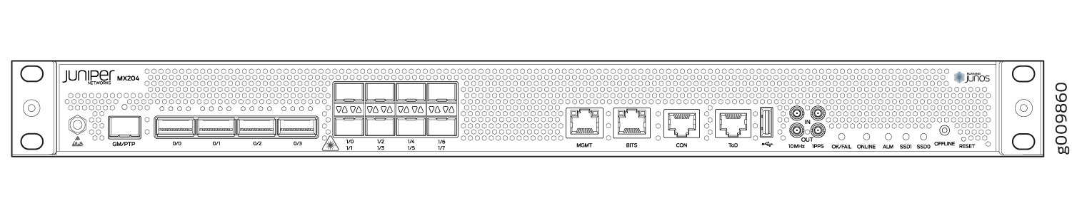
The MX204 has four rate-selectable ports that can be configured as 100-Gigabit Ethernet ports or 40-Gigabit Ethernet ports, or each port can be configured as four 10-Gigabit Ethernet ports (by using a breakout cable). The MX204 also has eight 10-Gigabit Ethernet ports. The four rate-selectable ports support QSFP28 and QSFP+ transceivers, whereas the eight 10-Gigabit Ethernet ports support SFP+ transceivers. For more information on the rate selectability support for the MX204 router, see MX204 Router Port Speed Overview.
Starting in Junos OS Release 18.3R1, you can
use the Mellanox 10-Gbps pluggable adapter (QSFP+ to SFP+ adapter
or QSA; model number: MAM1Q00A-QSA) to convert four lane-based ports
to a single lane-based SFP+ port. The QSA adapter has the QSFP+ form
factor with a receptacle for the SFP+ module. Use the QSA adapter
to convert a 40-Gbps port to a 10-Gbps (SFP+) or a 1-Gbps (SFP) port.
The 1-Gbps SFP port supports auto-negotiation. You can configure auto-negotiation
by using the command set interfaces interface-name gigether-options auto-negotiation. For more information, see auto-negotiation.
-
The interface name prefix must be
xe. -
Rate selectability at PIC level and port level does not support 1-Gbps speed.
For a complete list of supported optics on MX204, see MX204 Transceivers.
The router comes in two variants–AC-powered and DC-powered. Figure 2 and Figure 3 shows the rear of the fully configured chassis.
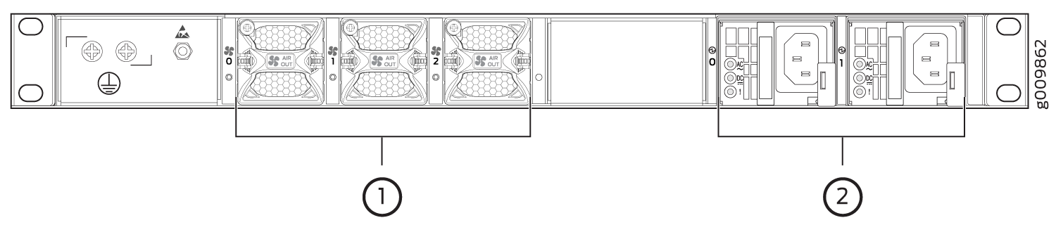
1 — Fan modules | 2 — Power supply modules (AC) |
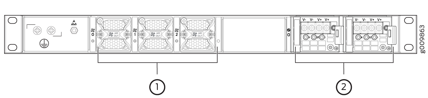
1 — Fan modules | 2 — Power supply modules (DC) |
The electrostatic discharge (ESD) points on the router are located both on the front and on the rear of the chassis. Figure 4 shows the electrostatic discharge (ESD) point on the router.
Before removing or installing components, attach an ESD strap to an ESD point, and place the other end of the strap around your bare wrist. Failure to use an ESD strap could result in damage to the hardware components.
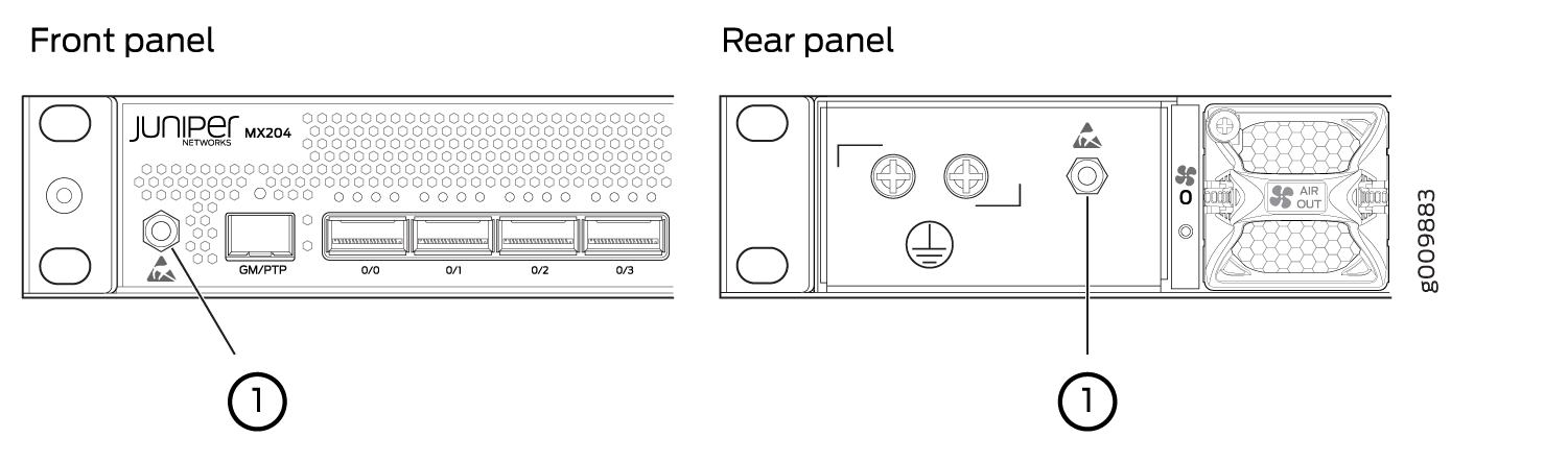
1 — ESD points |
MX204 Component Redundancy
A fully configured router is designed so that at no single point of failure can cause the entire system to fail. Only a fully configured router provides complete redundancy. All other configurations provide partial redundancy. The following major hardware components are redundant:
Power supplies—The router supports two power supply modules. The MX204 router provides 1+1 redundancy for the system. Both AC and DC systems can withstand the failure of a single power supply without system interruption in 1+1 redundancy mode. If one power supply fails in a fully redundant system, the other power supply can provide full power to the router indefinitely.
Cooling system—The cooling system has a total of three fan modules, which are controlled and monitored by the host subsystem. A fully configured router needs all the fan modules to operate normal. The fan modules are at the rear and are used to cool the router. If a fan fails or the temperature of the chassis rises above the temperature threshold, the speed of the remaining fans is automatically adjusted to keep the temperature within the acceptable range.
For a fully configured router, all the three fan modules and the two power supply modules must be operational, and in the event of any module failure the failed module must be replaced immediately.
See Also
MX204 Field-Replaceable Units
Field-replaceable units (FRUs) are router components that can be replaced at the customer site. Replacing most FRUs requires minimal router downtime. The router uses the following types of FRUs:
Power supply modules (if redundant)
Fan modules (if redundant)
Transceiver modules
See Also
MX204 Hardware Components and CLI Terminology
The MX204 router support the components in Table 1, listed in alphabetic order.
Component |
Hardware Model Number |
CLI Name |
Description |
|---|---|---|---|
Chassis |
MX204 |
|
|
Cooling system |
|||
Fan module |
JNP-FAN-1RU |
|
|
Power system components |
|||
Power supply module |
|
|
|
MIC |
N/A (built-in) |
|
N/A |
MPC |
N/A (built-in) |
|
N/A |
Routing Engine |
N/A (built-in) |
|
N/A |
Transceiver |
|
||
Table 2 lists the spare parts and blank panels available for the router.
Model Number |
Description |
|---|---|
JNP204-CHAS |
MX204 chassis, spare |
JNP-PWR-BLNK-1 |
MX204 power blank cover panel |
MX204 Front and Rear Panel Components
Front Panel Components
The front panel on the front of the router enables you to view status and troubleshooting information at a glance. The front panel contains LEDs for the router components, online/offline and reset buttons, auxiliary and console ports, clocking ports, and interface ports. MX204 Chassis Description shows the front of the fully configured chassis.
Rear Panel Components
The rear panel of the router has slots for the power supply modules and fan modules. The power and fan modules are installed from the rear of the router. MX204 Chassis Description and MX204 Chassis Description shows the rear of the fully configured chassis.
Table 3 lists the components on the rear panel of the MX204 router.
Component |
Slots |
Number of FRUs |
|---|---|---|
Power supply module |
0 and 1 |
2 |
Fan module |
0 through 2 |
3 |
Alarm LEDs on the MX204 Front Panel
One alarm LED—labeled ALM—is located on the front panel of the router. A red light indicates a critical condition that can result in a system shutdown, and a yellow light indicates a less severe condition that requires monitoring or maintenance.
Table 4 describes the alarm LED in more detail.
|
Shape |
Color |
State |
Description |
|---|---|---|---|

|
Red |
On Steadily |
Major alarm—Indicates a critical condition that can cause the router to stop functioning. Possible causes include component removal, failure, or overheating. |
| Red | Blinking |
Both major and minor alarms—Indicates that both major and minor alarm conditions are present. |
|
|
Yellow |
On Steadily |
Minor alarm—Indicates a serious but nonfatal error condition, such as a maintenance alert or a significant increase in component temperature. |
|
|
- |
Off |
No alarm are present. |